Validating directed graphs by applying formal concept
analysis to conceptual graphs
ANDREWS, Simon <http://orcid.org/0000-0003-2094-7456> and POLOVINA,
Simon <http://orcid.org/0000-0003-2961-6207>
Available from Sheffield Hallam University Research Archive (SHURA) at:
http://shura.shu.ac.uk/16869/
This document is the author deposited version. You are advised to consult the
publisher's version if you wish to cite from it.
Published version
ANDREWS, Simon and POLOVINA, Simon (2017). Validating directed graphs by
applying formal concept analysis to conceptual graphs. In: The IJCAI-17 Workshop
on Graph Structures for Knowledge Representation and Reasoning (GKR 2017 @
IJCAI), Melbourne, Australia, 19-25th August.
Copyright and re-use policy
See
http://shura.shu.ac.uk/information.html
Validating directed graphs by applying Formal
Concept Analysis to Conceptual Graphs
Simon Andrews and Simon Polovina
Conceptual Structures Research Group, Communication and Computing Research Centre| Department of Computing, Sheffield Hallam University, Sheffield, UK
[email protected], [email protected]
Abstract. Although tools exist to aid practitioners in the construction of directed graphs typified by Conceptual Graphs (CGs), it is still quite possible for them to draw the wrong model, mistakenly or otherwise. In larger or more complex CGs it is furthermore often difficult–without close inspection–to see clearly the key features of the model. This paper thereby presents a formal method, based on the exploitation of CGs as directed graphs and the application of Formal Concept Analysis (FCA). FCA elucidates key features of CGs such as pathways and dependencies, inputs and outputs, cycles, and joins. The practitioner is consequently assisted in reasoning with and validating their models.
1
Introduction
A directed graph–or “digraph”–is a graph whose edges have direction and are called arcs [7, 9]. Arrows on the arcs are used to encode the directional informa-tion: an arc from vertex A to vertex B indicates that one may move from A to B but not from B to A. Such graphs for example are used in computer science as a representation of the paths that might be traversed through a program, or in higher-level conceptual models where concepts are related to each other by relations that gain additional semantics (i.e. meaning) by defining the direction between the source and target concepts. A classic illustration is a cat that sits on a mat [14]. In this simple example ‘sits-on’ is the semantic relation where the direction goes from cat to mat and not vice versa.
CGs (Conceptual Graphs) are digraphs that enable modellers to express meaning in a form that is logically precise whilst being humanly readable, and serve as an intermediate language for translating between computer-oriented formalisms and natural languages [11, 15]. CGs graphical representation thereby serve as a readable, but formal specification language for systems design or other practitioners using this approach [8]. CGs are however drawn by hand. Although tools such as CoGui1
and CharGer2
exist to assist the practitioner in creating a well-formed CG that adheres to the prescribed grammar and syntax, there is no guarantee that a model created using CGs is correct in terms of its validity.
1
http://www.lirmm.fr/cogui/
2
The modeller may have a misconception of the system being modelled or may simply make mistakes in its construction–things that still conform to the syntax and grammar but result in an invalid model.
It can be difficult to explore and validate a large and complex CG by in-spection. It is this problem that this paper begins to address by providing an automated method whereby key features of CGs are captured, reported and visualised. The modeller would thus be assisted in exploring and validating their CGs. The method makes use of the inherent direction of Concept-Relation-Concept triples in CGs to transform these triples into binary relations and thus expose them to Formal Concept Analysis (FCA) [6]. The process is automated in a tool calledCGFCAand has two stages; firstly parsing a CG file (in the ISO common logiccgif format [15]) to extract the CG triples and secondly, convert-ing these triples into correspondconvert-ing binary relations that accentuate the directed pathways in the original CG, as described next in section 2. The triples-to-binaries function is carried out using an implementation of theTriples2Binaries algorithm, specifically described in subsection 2.1.
2
Transforming CG digraphs: triples into binary relations
If triples are extracted from a CG in the form Source Concept → Relation →
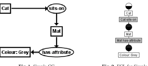
Target Concept, each such triple can easily be represented as a corresponding binary relation i.e. Source Concept-Relation, Target Concept. Where the Tar-get Concept then becomes a Source Concept for a following Relation, this can be captured in additional binary relations, where the original Source Concept-Relation is paired with subsequent Target Concepts. To illustrate the
source-Fig. 1.Simple CG Fig. 2.FCL for Simple CG
target structure, figure 1 shows a simple CG with the CG Concepts, [Cat],
[Mat] and [Colour: Grey]. [Cat] and [Mat] are linked by the CG
Rela-tion (sits-on) and [Mat], [Colour: Grey] are linked by (has-attribute).
[image:3.612.137.443.441.577.2]pair [Cat]→(sits-on)and thetarget concept[Colour:Grey]is dependent on
itssource concept-relation pair [Mat]→(has-attribute)(or alternatively, the
source concept-relation pair [Cat] → (sits-on) results in thetarget concept
[Mat]and thesource concept-relation pair [Mat]→(has-attribute)results in
thetarget concept [Colour: Grey]). The CG triple ([Cat],(sits-on),[Mat]) can be converted into the binary relation ([Cat]-(sits-on), [Mat]). Likewise the CG triple ([Mat], (has-attribute), [Colour: Grey]) can be converted into the binary relation ([Mat]-(has-attribute), [Colour: Grey]). There is also a binary relation between [Cat] and [Colour: Grey] indirectly through
[Cat]-(sits-on). Hence [Colour: Grey] also depends (indirectly) on [Cat],
which is of course sitting on that mat.
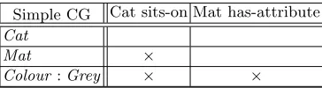
Simple CG Cat sits-on Mat has-attribute Cat
Mat ×
[image:4.612.215.397.269.319.2]Colour:Grey × ×
Fig. 3.The simple CG as a cross-table
The set of binary relations can be simply represented in a cross-table and fig-ure 3 shows the corresponding cross-table for this simple example, with rows rep-resenting CG Concepts and columns CG Source Concept-Relations. The cross-table is known as a Formal Context in FCA, so by converting CGs into these binary relations, FCA can then be applied. Figure 2 displays the resulting Formal Concept Lattice (FCL). This approach was derived after we compared it with Wille’s mapping of CGs to FCA (‘Concept Graphs’) in an earlier study [3, 16].
2.1 A triples-to-binaries algorithm
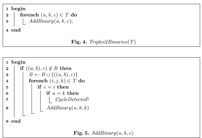
Figure 4 is an algorithm, Triples2Binaries, that along with its subroutine Ad-dBinary (Figure 5), converts a set of triples, T, into a corresponding set of binaries, B, exploiting the direction in the triples as explained above. It is a generalised form of theCGtoFCAalgorithm previously presented [3]. Whilst its application to CGs is the focus of this paper, the more general form makes it applicable to directed triples obtained from any source, including UML, RDF, OWL, Entity Relation Diagrams and linked data.Triples2Binariesalso includes some refinements not present inCGtoFCA, namely; improved efficiency by skip-ping repeated binaries and the ability to detect cycles. The main algorithm, Triples2Binaries, simply iterates through the set of triples, T, sending each triple, (a,b,c) to the subroutine AddBinary where the corresponding binary
((a,b),c) is added to the set of binaries, B. Line 2 ofAddBinary skips any
re-peated binaries. Line 4 performs a second iteration of the set of triples to detect indirect binaries in line 5: given two triples, (a,b,c) and (i,j,k), ifc=i there
begin 1
foreach(a,b,c)∈T do 2
AddBinary(a,b,c); 3
[image:5.612.130.484.112.355.2]end 4
Fig. 4.Triples2Binaries(T)
begin 1
if ((a,b),c)∈/B then 2
B←B∪ {((a,b),c)} 3
foreach(i,j,k)∈T do 4
if c=i then 5
if a=k then 6
CycleDetected! 7
AddBinary(a,b,k) 8
end 9
Fig. 5.AddBinary(a,b,c)
binary ((a,b),k) and repeat the process to detect further indirect relations. Line
6 provides the test for the presence of a cycle: if a source, a, becomes its own target,k, (directlyor indirectly) then a cycle is present. It can be determined by an implementation of the algorithm what exactly is to be done at this point; for example, to report or document the cycle in some way. Note that the algorithm does not use the detection of a cycle as a terminating condition for the recur-sion - the algorithm is allowed to complete the cycle and add the corresponding binary. It is the test for repeated binaries in line 2 that does the termination for cycles, thus preventing an endless loop. This is because the subsequent binary following the completion of the cycle will be a repeat.
3
Highlighting key features of a CG
When the CGFCAsoftware implementation3
ofCGtoFCA parses a CGcgif it creates a set of CG Source Concept, Relation, Target Concept triples (corre-sponding to the set of triples, T, in the Triples2Binaries algorithm, above). Once the set of triples has been created the implementation ofTriples2Binaries inCGFCAcreates the set of binaries as described above, in the form of an FCA formal context and outputs the corresponding cxt file. During the triples-to-binaries process,CGFCAdetects and reports the following CG features: Inputs, outputs and cycles. The formal context output byCGFCAcan then be visualised
3
as a Formal Concept Lattice (FCL) using an appropriate tool, such as Concep-tExplorer (ConExp)4
or as a Formal Concept Tree using In-Close [1, 2]. Such visualisations clearly highlight further CG features e.g. cycles and co-referent joins. The CG features are described in the following sub-sections, together with the way they are highlighted byCGFCA and their respective FCL.
3.1 Paths and Dependencies
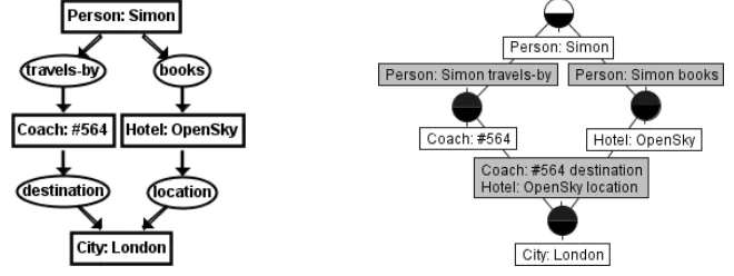
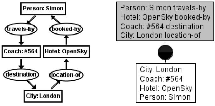
Figure 6 and 7 respectively illustrate the CG and FCL for the dependencies de-scribed earlier in a larger example–as well as two paths–between the source
con-cept[Person: Simon]and the target concept[City: London]. As well as the
intermediate target concepts that in turn become source concepts (i.e.[Coach:
#564] and [Hotel: OpenSky]), this example shows CG referents, namely
Si-mon, #564, OpenSky and London. ([Colour: Grey] from figure 2 was also a CG concept with a referent.) The referents are instances of their respective type label in the CG concept e.g. London is a referent of the type label City, and #564 the numeric identifier for a Coach that in the context of figure 6 could be read as the number of the coach that goes to London. In addition to the direct
de-Fig. 6.Paths and Dependencies CG Fig. 7.Paths and Dependencies FCL
pendencies such as[Hotel: OpenSky])on[Person: Simon]-(books)there are indirect dependencies detected in accordance with AddBinary line 4 described earlier in subsection 2.1. These are: a)[City: London])on[Person: Simon]
-(books), and b)[Person: Simon]-(travels-to) through the other path that
has the intermediate concept[Coach: #564]. The starting (or input) concepts and ending (or output) concepts are usefully displayed by theCGFCAsoftware i.e.Input concepts: ”Person: Simon”. Output concepts: ”City: London”. In simple terms, Simon’s trip to London depends on travelling there by coach and booking into the OpenSky hotel. Of course in this still-simple example this knowledge can be gleaned from the CG alone thereby obviating the need forCGFCA. However
4
[image:6.612.155.485.360.484.2]it is more likely that these patterns will appear in larger CGs where it is not so evident, perhaps unknowingly as they are drawn by hand and obfuscated by the size of the larger model. CGFCAand the consequent computer-generated FCL will highlight within such digraphs the ‘diamond’ looking patterns that represent multiple pathways thus alerting their existence–hence validity–to the modeller.
3.2 Cycles
[image:7.612.140.482.260.429.2]It is natural that digraphs may contain one or more cycles. Figure 8 and 9 re-spectively illustrate an example of a CG and FCL that is a cycle. Note that this
Fig. 8.CG that is a cycle Fig. 9.FCL of cycle
example is similar to the previous paths and dependencies example in figure 6 and 7. This time the direction of the hotel booking path goes in the opposite direction, thus creating the cycle. The renaming of the relations i.e. location
to location-ofandbooksto booked-bycorrectly reflect the new direction. It
is common however to name or use relations that cause cycles to occur inadver-tently such as possibly in this example. A cycle may of course be desired, but the modeller will in any event be alerted to its validity by the FCL (here figure 9) in accordance withAddBinary line 6 described earlier in subsection 2.1. The CGFCAoutput highlights why the figure 9 lattice looks as it does:Cycle involv-ing ”Hotel: OpenSky” ”Person: Simon” ”Coach: #564” ”City: London”. There are no input concepts. There are no output concepts.
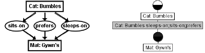
3.3 Joins
Fig. 10.CG with coferent concept Fig. 11.FCL with coferent concept
this case isGywninPetandCat. Where a source and target concept are directly linked by more than one relation, the associated relations are in effect co-referent. This behaviour is highlighted by figure 12 and 13. TheCGFCA parser detects
Fig. 12.CG with coferent relations Fig. 13.FCL with coferent relations
co-referent CG Concepts and co-referent CG Relations and because they refer to the same object or instance it joins the concepts and relations automatically. Furthermore it concatenates the concept type or relation labels, using ‘;’ as the delimiter. This is evident in the FCL for figure 11 (i.e. Pet;Cat) and 13 (i.e.
sleeps-on;sits-on;prefers). This approach is akin to the maximal common
subtype in CGs (or intersection); thus Gywn is a) a Pet Cat, and b) sleeps, sits on, and likes the Mat5
.
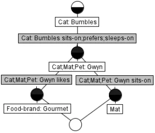
Another common error (particularly in larger or more complex models) is to give different types the same referent by mistake. Take for example the CG figure 12. In that figure let’s change[Mat: Gwyn’s]to[Mat: Gwyn], assuming that it was mistyped by the modeller in the first place. As a result, [Mat: Gwyn] will inadvertently join with the[Cat: Gwyn]and[Pet: Gwyn]CGs from figure 10. Figure 14 shows the CGs for this scenario including the mistake, and figure 15 demonstrates the result. Now Gwyn is not only a Pet Cat but a Mat too! And Bumbles sleeps-on, sits-on and prefers Gwyn as a Mat (rather than Gwyn’s Mat) while Gwyn sits on another Mat, all of which is nonsensical as the FCL reveals.
5
[image:8.612.132.484.309.401.2]Fig. 14.CG with coferent relations Fig. 15.Mistakenly Joined CGs FCL
Like the previous pathways and cycles examples, the practitioner is immediately presented with a need to reason with and validate their models.
3.4 Real Examples
Previous work has illustrated earlier versions ofCGFCA’s value in the business modelling domain [12]. A comprehensive, non-specific domain reference example is planned in an extended version of this paper, along with other CG features. Nonetheless the simple examples presented here show how digraphs can be val-idated throughTriples2Binaries as exemplified byCGFCA.
4
Concluding Remarks and Further Work
As well as providing validation, the FCL representation of CGs are arguably more readable. Arcs in a CG can lead in any direction and in a large, complex CG it can be difficult to trace and compare pathways through it, even more so where there are co-referent links. All FCL pathways are aligned in a top-to-bottom (inputs to outputs), hierarchical manner and co-referents can be automatically joined to make more apparent their connections and place in the graph.
Future work will develop the representative exemplar as a worked example as stated above; a worthwhile endeavour given the value demonstrated by this paper. The exemplar will includen-ary as well as binary relations. Furthermore since we have set the context as validating digraphs through triples to binaries rather than just CGs, further work includes directed triples modelled by prac-titioners in UML, RDF, OWL, Entity Relation Diagrams and linked data as alluded to earlier.
EL-Implications and Graph-FCA [4,5,13]. Extensive comparative studies in this arena already exist, pre-CGFCA[10]. A thread of further work is therefore re-quired to discover the comparative benefits of each approach, perhaps leading to how they may best work together in validating directed graphs through FCA.
References
1. Simon Andrews.In-close2, a high performance formal concept miner, pages 50–62. Conceptual Structures for Discovering Knowledge. Springer, 2011.
2. Simon Andrews and Laurence Hirsch. A tool for creating and visualising formal concept trees, volume 1637 ofCEUR Workshop Proceedings, pages 1–9. 2016. 3. Simon Andrews and Simon Polovina.A Mapping from Conceptual Graphs to
For-mal Concept Analysis, pages 63–76. Conceptual Structures for Discovering Knowl-edge. Springer, 2011.
4. Franz Baader and Felix Distel. A Finite Basis for the Set of EL-Implications Holding in a Finite Model, volume 4933 ofLecture Notes in Artificial Intelligence, pages 46–61. Springer, 2008.
5. S´ebastien Ferr´e and Peggy Cellier.Graph-FCA in Practice, pages 107–121. Springer International Publishing, Cham, 2016.
6. Bernhard Ganter and Rudolf Wille. Formal concept analysis: mathematical foun-dations. Springer Science & Business Media, 2012.
7. Frank Harary. Structural models: An introduction to the theory of directed graphs. {John Wiley & Sons Inc}, 1965.
8. Pascal Hitzler and Henrik Scharfe. Conceptual Structures in Practice. CRC Press, 2009.
9. Kenneth R. Koehler. Directed graphs. http://kias.dyndns.org/comath/33.html, 2012.
10. Jonas Poelmans, Dmitry I. Ignatov, Sergei O. Kuznetsov, and Guido Dedene. Re-view: Formal concept analysis in knowledge processing: A survey on applications. Expert Syst. Appl., 40(16):6538–6560, November 2013.
11. Simon Polovina. An Introduction to Conceptual Graphs, pages 1–15. Conceptual Structures: Knowledge Architectures for Smart Applications, July 2007, Sheffield, UK. Springer, 2007.
12. Simon Polovina, Hans-J¨urgen Scheruhn, Stefan Weidner, and Mark von Rosing. Highlighting the Gaps in Enterprise Systems Models by Interoperating CGs and FCA, pages 46–54. Proceedings of the Fifth Conceptual Structures Tools and Interoperability Workshop (CSTIW 2016). CEUR-WS, 2016.
13. Mohamed Rouane-Hacene, Marianne Huchard, Amedeo Napoli, and Petko Valtchev. Relational concept analysis: mining concept lattices from multi-relational data. Annals of Mathematics and Artificial Intelligence, 67(1):81–108, 2013.
14. John F. Sowa. Conceptual graph examples.
http://www.jfsowa.com/cg/cgexampw.htm.
15. John F. Sowa. Conceptual Graphs, pages 213–237. Handbook of Knowledge Rep-resentation, Foundations of Artificial Intelligence. Elsevier, Amsterdam, volume 3 edition, 2008.