Comprehensive Geometric and Pavement Design of Kabaya Road,
Rwanda
Vincent Harelimana
1, Pierre Gapfizi
2, Patrick Nteziryayo
3, Fabien Bizabarimana
4, and Albert
Salomon Kibugenza Umuhuza
5Hohai University, Department of Civil Engineering, Xikang Road, Gulou District, Nanjing City, Jiangsu Province,
China, Postcode
:
210098
Rwanda Polytechnic, Musanze College, Department of Civil Engineering, P.O. Box: 226 Musanze-Rwanda
---***---Abstract:- The objective of the project was to conduct geometrical and pavement design of road located in Ngororero district, country of Rwanda and for achieving the intended objective, the raw data of the study were collected first by conducting topographic survey which helped to get both safe horizontal and vertical alignment. Secondly, different soil tests like CBR was conducted to determine the thickness of subbase layer, modified proctor was conducted to predict the optimum moisture content and maximum dry density respectively required during compaction on the field, Atterberg limits were conducted to know the plasticity of the soil mass and sieve analysis test was performed to know the soil contents and their behavior under applied load. Thirdly, the traffic survey was conducted in order to know the thickness of road base plus surfacing layer. The work was completed in Cavadis for the side of Auto-CAD, Autopiste, and Piste for geometric design and then after in Arc GIS for rendering works. Traffic survey was done and the 60km/hour was chosen as design speed, Carriageway width of 7m and shoulder way of 1.5m was selected according to law No 55/2011 of 14/12/2011. The obtained results indicated the thickness of sub base layer as 225mm, the
thickness of road base as 170mm and surfacing layer as 100mm and the total road covered the length of 11.447 km.
Key Words:Traffic survey, geotechnical tests, geometric design, pavement design, Kabaya road
1. Introduction
The road is one of different infrastructures to respond to the requirements of the people’s activities. Historically people have to travel and goods have been moved by different means of transportation, some of them is the road. As civilization developed and people’s desire for communication increased, the design and techniques of construction vary time to time depending on economic, financial means, the materials available for construction and traffic loading by its growth rate over the design life. In practice, a road pavement structure is superimposed layers of selected and processed materials that is placed on well compacted soil or sub grade (Flaherty, 2002).
Once it is constructed, it will not last forever because with time, signs of destruction will appear referred to the number of traffics. These signs include cracking, cutting and polishing of the road’s surface. A point will arrive where the road defects are at such an advanced stage that the integrity of pavement and hence the standard of service provided by it has diminished. Rehabilitation is required at this point to prolong the road’s useful life. Loss of skid resistance and loss of texture are forms of deterioration that usually suffered by all Road pavements (Flaherty, 2002).
The combination of effects of traffic loading and the environment cause pavements to deteriorate over time. The deterioration effects need to be restored by adding or replacing material in the existing pavement or reconstruction of it. This term is known as rehabilitation which is a structural or functional enhancement of a pavement for producing a substantial extension in service life, by improving pavement condition and ride quality. Rwanda is a country in central Africa where economic activities and Tourism are progressively raising. Markets, health centers and Guest houses are numerous in its different towns and centers; one of them is Ngororero District. Since the country is getting more and more developed, the movement of Tourists, Population and their goods also increases, this requires sufficient transport means, particularly well-developed roads.
The road said in this case study connects the main road in Kabaya with very important infrastructures such as: Kabaya market, Kabaya police station, Kabaya hospital and Kabaya health center where a big movement of population is encountered. The structural state of this Road together with its geometrical elements has generated the thought of its geometrical and pavement design.
2. Problem Statement
steeper so that laden vehicles sometimes slide, its vertical profile was highly damaged so that stopping sight distances were not adequate, it had not shoulders, it had not cross fall and due to these, the potholes and gullies were developed from many years ago and cause different problems like damaging the springs of passing vehicles, waterlogging on the road’s surface during winter seasons and weakness of underlying layers, it had not the side ditches for conveying the water coming from the catchment areas and on the pavement, due to this, the road’s structure was damaged easily and activities of people near by the road of this case study always were damaged by the storm water due to lack of its management. In fact, all these problems make Kabaya road to be isolated and remain under developed compare to other centers in Kabaya district. By conducting road geometric design, pavement structural design and design longitudinal side ditches with appropriate standard and dimensions, the solutions about the problems counted between those centers would be obtained.
So the only solution was to provide new cross sectional elements which could support the mobility of the road users, horizontal elements with adequate radius of curvature and visibility sight distances, and vertical profile with the appropriate sight distances and allowable gradients to improve its capacity performance appropriate, to provide pavement structure which is capable of supporting the loads from traffics.
3. Materials and Methods
This section presents materials and methods used to achieve the targeted goal of the study. The research materials consisted of materials which are supposed to be used in topographic survey, construction of sub base courses, construction base courses of the road layers. All methods used within this research are presented in this section.
3.1 Description of study area
Kabaya road is located in western province of Rwanda, Ngororero district, Kabaya sector, specifically in Kabaya and Rurembo cells.
Figure-1:
Kabaya road-Kabaya health centre
3.2 Terrain analyses and Selection of design standards
3.3 Topographic survey
Topographic survey was carried out to gather more topographic coordinates and this leads determination of profile and cross-sectional drawings with full details to be used during implementation of this project. Field survey was carried out by three stages: reconnaissance survey, establishing of control point, topographic survey.
Reconnaissance survey
This was done as an exhaustive study which preliminarily done by analyzing aerial photos and then site survey of the land which was about to be surveyed. This was done both by arrival to the site and by aerial observation. The main purpose was to know exactly the different information available on the site and to choose suitable positions of the stations.
Establishing of control point
Table-1: Setting of control points
STATION X Y Z
B.M 458381.666 4793113.137 1715.066
R1 458190.571 4792353.390 1725.946
ST1 457560.746 4792181.520 1761.743
R2 457987.476 4791914.487 1793.144
ST2 457186.769 4791773.442 1848.949
R3 457451.361 4791437.190 1860.432
ST3 457043.448 4791519.875 1884.194
R4 456767.970 4791219.401 1895.208
ST4 456310.411 4791445.424 1847.187
R5 456293.873 4791175.299 1832.617
ST5 456029.261 4791230.427 1810.871
R6 455969.017 4791055.791 1805.576
ST6 455832.882 4791139.566 1786.039
R7 454799.918 4791428.886 1785.073
ST7 454717.227 4791219.401 1785.139
R8 454540.819 4791346.195 1811.416
ST8 454557.357 4791450.937 1823.231
R9 454452.615 4791428.886 1832.216
ST9 454364.411 4791296.580 1824.973
3.4 Topographic Survey
Field survey was carried on the road Kabaya by use TS 06 total station, and by referring to the point of known elevation Bench Mark (B.M) to collect other coordinates.
3.5 Traffic survey and traffic forecasting
Traffic count was done by manual classified count method and it was done in 7 days, one count in weed-end and other three days in the week days.
Estimated full day count=
Calculation of design life Traffic
Calculation damaging Factor
Calculation of cumulative number of standard axle loads
Calculation of N, the cumulative number of standard axles N = Tn * D
3.6 Geometric design
Table-2:
Stopping sight distance
S/N
INPUTS
Formula
Stopping site
distance
V(km/h) =60, t(s)= 2.5,
G (%) =7, g = 9.81,
a = 3.4 m/sec
2D=vt+
Table-3:
Minimum length of rest curve
S/N
INPUTS FormulaMinimum length
of crest curve
(%) = 9.5, G2
S(m)=59.57, G1
(%) =7, h1=1.05,
h2=0.2
Table-4:
Minimum length of sag curve
S/N
INPUTS
Formula
Minimum length
of sag curve
S(m)=59.57, G1
(%) = 9.5, G2 (%)
=4.84, h1=1.05,
h2=0.2
L=2
*
L
For,
L
L
For, L
Table-5:
Minimum length of sag curve under obstacle
S/N
INPUTS
Formula
Minimum length
of rest curve
under obstacle
S(m)=59.57), G1
(%) = 2.5, G2 (%)
=4.66, h1=1.05,
h2=0.2, CL=5.7
Table-6:
Horizontal alignment
S/N
INPUTS
Formulae
Minimum length
Horizontal radius
v(km/h) =60, f = 0.15
eo=25, e=7
Setback distance
S(m)= 59.57, R (m)=94.488
Minimum length
Of transition curve
R(m)=94.488
Lmax=
Shift
L(m)=47.620, R(m)=94.488
𝑆
=
3.7 Laboratory work
During the technical study of this research Comprehensive design of pavement of Kabaya road, Rwanda in the civil engineering laboratory test method, sample preparation, test procedures and reporting were referred to the laboratory soil testing books (Laboratory, 2000)
Sieve analysis: The sample into riffle box was subdivided using the cone-and-quarter method, 3kg of the sample were selected using scoop and mixed with water to form a slurry , the sample was washed through a sieve with an opening of 0.075mm until the water became clear while collecting some passing materials, the retained mass of the sample was put in the drying oven, after 24 hours the sample was removed from the drying oven and put immediately in the desiccators until it cooled, the dry mass was weighed to know the quantity of passed fine materials; then the dry sample was put in the mechanical sieve shaker and was shaken for 10min then for each sieve the mass retained weighed (Laboratory, 2000).
Proctor Test: This test is performed to reduce the liquefaction, permeability and compressibility under working loads (it is mostly done by reduce the voids and increasing the dry density) and this test was done with referring to standards of BS 1377 part 4, 1990. The main target of proctor test is done for obtaining the optimum moisture content and maximum dry density and those are the important values to be considered during soil compaction for making highway/road layers (Day, 2001).
CBR test : The CBR test was done based on the British standard as a reference (British Standards Institution, 1990). The California Bearing Ratio test noted as CBR test was used as measure of resistance of a material to penetration of standard plunger under controlled density and moisture conditions. It was developed by the California Division of Highways as a method
of classifying and evaluating soil subgrade and base course materials for flexible pavements(Day 2001; Oregon Department of transporation 2019).
Liquid limits: Consistency is term used to indicate the degree of firmness of cohesive soils. The physical properties of clay greatly differ at different water contents and this test was done by referring (Department transporation, 2019). A soil which is very soft at a higher percentage of water content becomes very hard with decrease in water content (British Standards Institution, 1990).
4. Results and interpretations
Referred to the results obtained in the below Table7; it is found that the terrain on which the road is supposed to pass is mountainous.
Table-7:
Terrain analysis
Max Elevation(m)
Min Elevation(m)
Average gradient
(%)
Terrain classification
(Number of contours)
2216
2125
6
30
According to Robinson & Thagesen, (2004) terrain is mountainous.
4.1 Traffic forecasting
Conversion of partially traffic counts into estimated full day counts
The average daily traffic
Where heavy vehicles correspond to 30 % (155veh/day) and light vehicles correspond to 70% (371 veh/day).
Table-8:
Traffic forecasting
Damaging factor
Design life
Traffic (msa)
Cumulative Number of Standard Axles (msa)
D=4.136
tn =1.870
7.73~ 8
The ORN 29 and 31 methods are valid for designs up to 40 and 30 million standard axles respectively (Rogers,
2003). So, it means that this project can be conducted by referring to these standards.
4.2 Design geometric parameters
Table-9:
Calculated horizontal alignment elements
Horizontal alignment
V(Km/h) emax %
Fmax Radius
R(m)
Transition curve
length(m)
Shift(m)
distance(m)
Visibility
Table-10:
Vertical alignment
Vertical alignment
K
Crest curve length (m)
sag curve length (m)
63.8
19.14
---
39.41
35.47
Table-11:
Calculated stopping sight distance elements
Stopping sight distance
V(km/h)
t (sec)
a (m/sec2)
Distance D (m)
60
2.5
3.4
59.57
4.3Tests for subgrade soil
Table-12:
Results of sieve analysis test
SIEVE ANALYSIS
sample I
sample II
sample III
sample IV
Sieve
size(mm)
%
Retained
%
Passing
%
Retained
Passing
%
%
Retained
%
Passing
%
Retained
%
Passing
75
0
100
0
100
0
100
0
100
50
0
100
0
100
0
100
0
100
37.5
8.1
91.9
2.4
97.6
0
100
0
100
28
12.7
87.3
5.4
94.6
1
99
1
99
20
14.5
85.5
10.3
89.7
3.8
96.2
4.3
95.7
14
25.1
74.9
20.7
79.3
10.7
89.3
10
90
10
34.7
65.3
34.1
65.9
23.5
76.5
17.2
82.8
6.3
49.3
50.7
48.6
51.4
40.8
59.2
32.2
67.8
5
54.2
45.8
53.3
46.7
47.4
52.6
38.2
61.8
2
71.9
28.1
68
32
65.9
34.1
58.2
41.8
1.18
76.3
23.7
73.4
26.6
72.6
27.5
63
37
0.425
78
22
77.4
22.6
77.6
22.4
65.3
34.7
0.3
78.9
21.1
81.1
18.9
81.3
18.7
69.4
30.6
0.15
83.7
16.3
83.6
16.4
84.2
15.8
74
26
Chat-1:
Combined results of sieve analysis
Table-13:
Soil classification based on AASHTO
Classification
Collected
sample
%
passing
(N0 10)
% passing
(N0 40)
% passing
(N0 200)
soil group
Soil class
sample I
28.1
22
15.8
A-1-b
Gravels
sample II
32
22.6
15.7
A-1-b
Gravels
sample III
34.1
22.4
14.8
A-1-a
Gravels
sample IV
41.8
34.7
17.4
A-1-b
Gravels
Granular materials (F200<35%)
Table-14:
Soil classification by ASSHTO
Group classification
A-1-a
A-1
A-1-b
A-3
Sieve analysis
(percentage)
No. 10
50 max
No. 40
30 max
50 max
51 min
No. 200
15 max
25 max
10 max
Characteristic of
fraction passing No. 40
Liquid Limit
…...
Plasticity index
6 max
NP
Usual types of materials
Based on the obtained results from the above table, the tested construction material (soil) samples were classified as stone fragments, gravel and sand material with no presence of clay and it was classified as gravel material with respect to (AASHTO) and ASTM (D3282-09). The percentage of granular material is in the range of 82.6-85.2 (% retained on sieve No 10 +% retained on sieve No 40+% retained on sieve No 200) with group index of zero which is the best construction material for subgrade since it is inversely proportional to Group Index.
Table-15:
Results for Proctor test
COMBINED RESULTS OF PROCTOR TEST
Sample I
Classification
DD
1.965
1.993
2.014
1.965
MDD 2.014 Quite good
MC %
7.1
9.2
11.2
13.4
OMC
11.2 good
Sample II
DD
1.928
1.965
1.998
1.947
MDD 1.998 good
MC %
6.7
8.8
10.8
12.6
OMC
10.8 good
Sample III
DD
1.921
1.955
1.983
1.946
MDD 1.983 good
MC %
8.3
10.4
12.6
14.4
OMC
12.6 good
Sample IV
DD
1.924
1.941
1.962
1.936
MDD 1.962 good
MC %
8.8
10.9
12.8
14.7
OMC
12.8 good
Chat-2:
combined results of proctor test
materials since its Maximum dry density is in the range of 1.3 to 2.4 while II,III and IV were classified as good materials as it is in the range of 1.6 to 2.0by referring to AASHTO(1978) designation T180 and ASTM (1980) designation D 1557.
Table-16:
Results of Atterberg limits test
ATTERBERG LIMITS TEST
LIQUID LIMITS
PLASTIC LIMIT PLASTIC INDICES
Sample I
Blows
15
21
25
31
35
WL Plastic limit
Plastic Indice
MC (%)
29.7 27.9 26.8 24.6 23.1
26.3
18.2
8.6
Sample II
Blows
14
21
25
30
35
WL Plastic limit
Plastic Indice
MC (%)
31.9 29.2 27.5 25.7 23.3
27.3
17.7
9.8
Sample III
Blows
15
21
25
31
35
WL Plastic limit
Plastic Indice
MC (%)
32.4
30
28.3 26.1 24.2
28.3
17.9
10.4
Sample IV
Blows
14
20
25
31
35
WL Plastic limit
Plastic Indice
MC (%)
31
29.2 27.6 25.4 23.9
27.7
18.5
9.2
According to Garber & Hoel (2002), Since this soil is found in A-1-a and A-1-b, thus the soil is granular material and can be used as a subgrade or sub base material satisfactorily if properly drained, in addition, such soils must be well compacted and protected with an adequate thickness of pavement for the surface load to be supported. The following figure presents Atterberg limits results from the above table 15 for sample1, Sample 2, Sample 3 and Sample 4.
Table-17:
Results of CBR test
Sample I
Penetration(mm)
0
0.63 1.25
2
2.5
3
4
5
6
7
8
9
10
Load (KN)
0
83
113 143
173
225 315
398
458 593 653 705 728
Sample II
Penetration(mm) 0 0.63 1.25
2
2.5
3
4
5
6
7
8
9
10
Load (KN)
0
75
113 173
203
240 330
383
428 473 518 548 585
Sample III
Penetration(mm) 0 0.63 1.25
2
2.5
3
4
5
6
7
8
9
10
Load (KN)
0
98
120 150
195
225 263
293
323 383 443 480 510
Sample IV
Penetration(mm) 0 0.63 1.25
2
2.5
3
4
5
6
7
8
9
10
Load (KN)
0
98
143 188
203
218 263
330
375 405 450 473 488
0 100 200 300 400 500 600 700 800
0 1 2 3 4 5 6 7 8 9 10 11
Load(
N)
Penetration (mm)
COMBINED RESULTS OF CBR TEST
TP 1 TP 2 TP 3 TP4
Chat-4:
combined results of CBR test
CBR Calculation
blows
Penetration(mm)
Load(N)
Formula
Results
(%)
Sample I
55
5
398
(19.35/1.05)
19
Sample II
55
5
383
(19.35/1.05)
18
Sample III
55
5
293
(19.35/1.05)
15
Sample IV
55
5
330
(19.35/1.05)
16
Design CBR
Result
(%)
After conducting CRB test, the obtained results from Table 16 and Figure 4 indicated that design CBR is 11.5 % and according to Rogers (2003), in the below table 17, this CBR value is satisfactory for subgrade construction material.
Pavement structural design
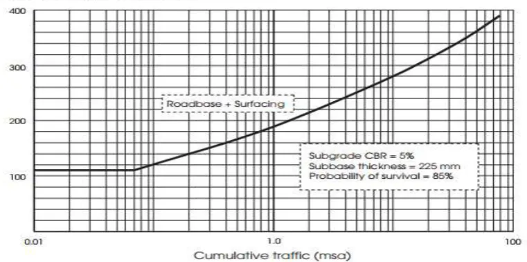
[image:12.595.54.544.202.339.2]The below Table 17 indicates the thickness requirements for both sub base material alone and combination of sub base and capping for different CBR values of the underlying subgrade materials (Rogers, 2003)
Table-17: The required thickness based on CBR value
Layer
CBR of subgrade
<2
2
3
4
5
Sub base thickness(mm)
615
400
310
260
225
Sub base + Capping comprising
-S
ub base thickness(mm)
-C
apping layer thickness (mm)
150
600
150
350
150
350
150
350
225
---
According to Rogers (2003), the sub base and capping layer act as a regulator of the surface of the sub-grade below and protect it against the effects of inclement weather. They are along with the subgrade, provide a secure platform on which the upper layers of the highway pavement can be built. The dominant of the thickness of this pavement section is the strength of the underlying subgrade. Its design is independent of cumulative traffic incident on the upper layers of the pavement over its design life. For subgrade in excess of 5% CBR, the required sub base depth is no greater than 225mm, down to a minimum of 150mm at a subgrade CBR of 15 % (HD 25/94).
Figure 2: Showing Design curve for highways with bituminous road base. Source: (Rogers, 2003)
Granular and cement based sub base are recommended for flexible pavements (HD25/94).
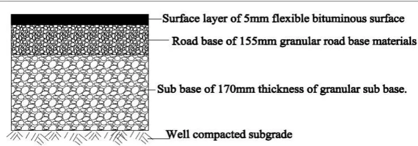
[image:12.595.107.488.444.633.2]Figure 3: Typical section of pavement structure
5. Concluding Remarks
Kabaya road was designed to meet the projected traffic and Ngororero master plan layout requirements as it was the main objective of the study. The geometric design has been achieved by following AASHTO design procedure. In fact, geometrical parameters such as stopping sight distance, vertical curve length, simple horizontal curve radius and transition curve has been calculated using a prepared spread sheet to complete road geometric design input parameters. The design covered 11.447 km, where the 60 km/hour was chosen as design speed and a carriageway width of 7m and width of the shoulder 1.5m.
In addition, this project involved the selection of appropriate pavement and surfacing materials to ensure that the pavement of the road section said in the case study will perform adequately the functions for which it is designed and will require minimal maintenance under the anticipated traffic loading for the design period adopted. It has given the appropriate thickness and composing materials for that road section to withstand traffic loads passing on it. The project provided a road section of width that is minimized so as to reduce the cost of construction and the maintenance, whilst being sufficient to carry the traffic loading efficiently and safely. The pavement surface is covered by an impermeable layer for the protection of the foundation which can be softened by the entrance of water if it is not adequately treated.
The results found are as follow: minimum horizontal radius was found to be 95m corresponding transition curve was found to be 47.74m, stopping site distance was found to be 59.57m, crest curve length was found to be 19.14m, sag curve length was found to be 35.47m, according to the results obtained from sieve analysis the soil was found to be gravel soil, design CBR was found to be 11.33%.
6.Acknowledgements
This research was achieved due to good partnership with laboratory technicians of Institut d'Enseignement Superieur de Ruhengeri during geotechnical laboratory tests. We really appreciate the provided best advices, suggestions and comments from different lecturers whom we work together during this conducted research. All the used equipment and materials used were from INES-Ruhengeri Laboratory, Civil engineering department and Land surveying department due to this reason, we highly appreciate the top managers of the Institution. and the materials used were also provided for facilitating us during the whole research.
The special thanks are addressed to our family for their invaluable care, encouragement and support throughout our daily activities and success of this research. We cannot forget to thank all those people who have contributed in one way or another for the realization of this research. We also thank our Almighty Lord who has granted us a good health and ability to work hard through the whole period of our engineering career.
REFERENCES
AASHTO. (2001). A policy on geometric design of highways and streets (4th Ed.). Washington.D.C: Taylor & Francis Group.
Elfino, K. M., Roger, C. R., Shiells, D., & Smith, K. M. (2000). Pavement design guide for subdivision and secondary roads in Virginia (4th ed.). Virginia: Materials Division.
Fwa, T. F. (2006). The Handbook of highway engineering (2nd ed.). Singapore: Taylor & Francis Group, LLC.
Holts, R. D., & Kovacs, W. D. (1981). Introduction to geothecnical engineering (2nd ed.). Washington. D.C: Prentice- Hall. pp 435-678
Rogers, M. (2003). Highway engineering (2nd ed.). Dublin: Wiley-Blackwell.
Rolt, J. (1993). Overseas road note 31,a guide to the structural design of bitumen-surfaced roads in tropical countries and sub-tropical countries (4th ed.). London: Overseas Development Administration.
Rolt, J., Hewitt, N., Parsley, L., & Elsworth, N. (2004). Overseas road note 40,a guide to axle load surveys and traffic counts for determining traffic loading on pavement (4th ed.). London: Department for International Development.
Garber, N. J. & Hoel, A. L (2002). Traffic and highway engineering (4th ed.). Virginia: Elsevier .
Rutajama, S. S., & Overby, C. (2000). Laboratory testing manual. Dar-Es-Salaam: Government of Tanzania.