ISSN Online: 2331-4249 ISSN Print: 2331-4222
DOI: 10.4236/wjet.2018.63034 Jul. 23, 2018 567 World Journal of Engineering and Technology
Error Analysis of Radial Motion Measurement
of Ultra-Precision Spindle
*
Risheng Zhang
1, Jialin Yang
1#, Erwei Shang
2, Yanqiu Chen
2, Yu Liu
21Institute of Machinery Manufacturing Technology, China Academy of Engineering Physics, Mianyang, China 2School of Mechanical Engineering, Jiangnan University, Wuxi, China
Abstract
This paper gives an error analysis of radial motion measurement of ul-tra-precision spindle including nonlinearity error of capacitive displacement probes, misalignment error of probes, eccentric error of artifact ball and error induced by different error separating methods. Firstly, nonlinearity of a capa-citive displacement probe targeting a spherical surface is investigated through experiment and the phenomena of fake displacement induced by lateral offset of the probe relative to an artifact ball are discussed. It is shown that the error motion in radial and axial direction and eccentric rotation of artifact ball will both induce lateral offset which causes a fake output of probes. Moreover, measurement error induced by angular positioning error for three famous er-ror separating methods is detailed.
Keywords
Error Motion, Spindle Metrology, Ultra-Precision Spindle, Error Analysis
1. Introduction
Ultra-precision spindle or rotating table usually working on aerostatic or hy-drostatic principle plays an important role in ultra-precision machine tools. The rotational accuracy of spindle is a main factor influencing the machining accu-racy of ultra-precision machine tool [1]. Traditional method no longer applies to error motion measurement for ultra-precision axis because of artifact form er-ror. As a result, several error separating methods have been developed. The most well-known methods such as Donaldson reversal, multi-steps and multi-probe have been demonstrated to approach uncertainty on order of nanometers [2] [3] *Supported by National Science and Technology Major Project of High-level Numerical Controlling Machine Tools and Basic Manufacturing Equipment with the granted No. 2017ZX04011001. How to cite this paper: Zhang, R.S., Yang,
J.L., Shang, E.W., Chen, Y.Q. and Liu, Y. (2018) Error Analysis of Radial Motion Measurement of Ultra-Precision Spindle. World Journal of Engineering and Tech-nology, 6, 567-574.
https://doi.org/10.4236/wjet.2018.63034
Received: June 1, 2018 Accepted: July 20, 2018 Published: July 23, 2018
Copyright © 2018 by authors and Scientific Research Publishing Inc. This work is licensed under the Creative Commons Attribution International License (CC BY 4.0).
http://creativecommons.org/licenses/by/4.0/
DOI: 10.4236/wjet.2018.63034 568 World Journal of Engineering and Technology spherical surface [6].
2. Error Analysis
2.1. Capacitive Probe Nonlinearity Targeting Ball Surface
In order to study nonlinearity of a capacitive probe moving laterally relative to a spherical surface, an experiment is conducted shown in Figure 1(a) where the probe moves laterally every time by some micrometers while a same probe is used to measure the lateral displacement. The data is shown in Figure 1(b) and a quadratic curve is used to fit the experimental data. It is obvious that the non-linearity exists when the probe moves laterally above the spherical surface. This leads to two problems when measuring radial error of axis of rotation. One is whether the linear gain will change when the probe targeting spherical surface at different lateral offsets. The other is the lateral component of eccentric move-ment of artifact ball may lead to additional reading error of a capacitive probe which will be discussed later in section 2.2. To investigate the former problem one experiment is made in which readings of a probe approaching the artifact ball at different lateral offsets and the results are shown in Figure 1(c). It is con-cluded that the linear gain remains constant when lateral displacement varying between 0 and 40 μm. When measure error motion, the lateral displacement is always keep minimum by adjusting the probe in lateral direction to approach the highest point of the artifact ball and this will ensure the linear gain is constant.
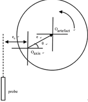
2.2. Eccentricity Induced Lateral Misalignment
A misalignment between the artifact and axis of rotation leads to eccentric error in the probe signals. Two primary methods exist to eliminate this effect, such as the least quadratic circle and the Fourier analysis to remove the fundamental frequency. However, little attention is given to the fact that lateral component of eccentric movement vector of artifact ball may lead to additional reading error of capacitive probe. Set the eccentric error to be e. At angular position θ, the lateral and the radial components of eccentric error are e∗cosθ and e∗sinθ
respectively. Assuming the initial lateral offset of the probe e0 relative to the ball is shown in Figure 2.
DOI: 10.4236/wjet.2018.63034 569 World Journal of Engineering and Technology (a)
(b) (c)
[image:3.595.210.538.65.413.2]Figure 1. Nonlinearity of a capacitive sensor induced by lateral offset relative to a spherical artifact. (a) Experiment setup; (b) Capacitive probe output when moving laterally at different offset distances. y1 and y2 are quadratic and cubic fitting equations respectively; (c) Experiment data to identify the output characteristic of capacitive probe at different lateral offset distances.
[image:3.595.282.462.495.705.2]DOI: 10.4236/wjet.2018.63034 570 World Journal of Engineering and Technology
2 2
From this formula, second order and first order errors will be included in the probe output and when the eccentric error e = 5 μm the second order error will be up to 10 nm which will be an unacceptable error and be impossible to be eliminated by mathematical method. The last two 1st order components in this formula can be removed by Fourier analysis to remove the fundamental fre-quency.
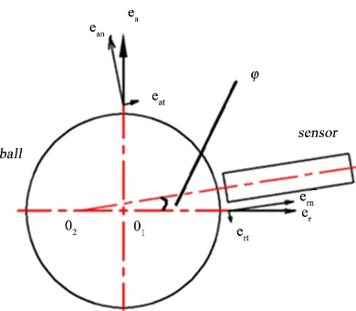
2.3. Misalignment Error of Probe: Tilt Error
When considering radial error motion, one of the important error sources is at-tributed to misalignment between the capacitive probe and the artifact ball as is shown in Figure 3. The probe output is affected by four error motion compo-nents of which two are in the error sensitive direction and the other two in the error insensitive direction. The components have the following relationship:
a = an+ at
e e e (3)
r= rn+ rt
e e e (4) where, eat and ert are error motion components in the error sensitive dire-cion, ern and ean in the error insensitive direction, and ea is the axial error motion and er the radial error motion. Accordingly, the output m1 of probe can be expressed as the combination effects of two parts, namely
1 x
m S= +E (5)
where Sx and E are radial error motion in X direction and the error induced by misalignment, respectively. We have
(
)
rn at an rt r
E e= +e + f e +e −e (6)
Substituting ern=ercosϕ and eat=easinϕ in to (6) yields
(
cos 1)
sin(
)
r a an rt
E e= ϕ− +e ϕ+ f e +e (7) where function f
( )
⋅ corresponds to the lateral offset effects which is detailed in section 2.1 and ϕ is the tilt angle. Considering the lateral offset ean andrt
e are much smaller relative to the initial distance e0, we have
(
) (
)
2 20 0
an rt an rt
f e +e =a e e+ +e −ae (8)
(
an rt)
2 0(
an rt)
DOI: 10.4236/wjet.2018.63034 571 World Journal of Engineering and Technology
Figure 3. General misalignment between the probe and the artifact.
when ϕ is small enough, we have
(
)
0
2
a an rt
E e≈ ϕ+ ae e +e (10)
It can be concluded from (2) and (10) that the error motion in radial and axial direction and eccentric rotation of artifact ball will both induce lateral offset which causes a fake output of probes. When axial error motion is 0.4 μm and the initial lateral offset e0 is 20 μm, the maximum error due to lateral offset effects is up to 13 nm, which is a large measurement error in calibration of an ultra-precision spindle.
3. Positioning Error of Different Error Separations Methods
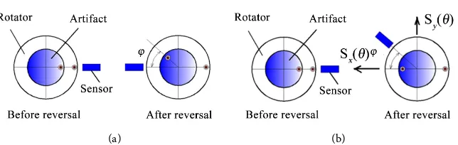
3.1. Donaldson Reversal Method
Let the angular positioning error of artifact after reversal be ϕ which is shown in Figure 4(a), then the measurement error induced by angular error after re-versing the artifact is derived as
( )
( )
(
)
( )
2 2
R R
E θ = θ − θ ϕ+ ≈ −ϕR′ θ (11)
where R
( )
θ is roundness of the artifact.The Donaldson reversal method needs to rotate the probe by 180 degrees rela-tive to the rotor of the spindle measured at the same time. Angular position er-ror of the probe will be introduced into the measurement signal. This kind of error is illustrated in Figure 4(b). The corresponding measurement error is de-rived as
( )
(
)
( )
( )
2 x cos y sin
M θ =R θ ϕ− −S θ ϕ+S θ ϕ (12)
( )
1( )
2( )
( )
2 x
M M
E θ = θ − θ −S θ (13)
( )
1( )
(
)
(
cos 1)
sin2 x y
DOI: 10.4236/wjet.2018.63034 572 World Journal of Engineering and Technology
( )
1(
( )
)
1( )
2( )
( )
42 y 2 x
E θ ≈ ϕ R′ θ −S − S θ ϕ +ο ϕ +ο ϕ
(15)
where Sx and Sy are error motion components in X and Y directions respec-tively. If
ϕ
is efficiently small and the measurement error will be simplified as( )
1(
( )
)
( )
2 y
E θ ≈ ϕ R′θ −S +ο ϕ (16)
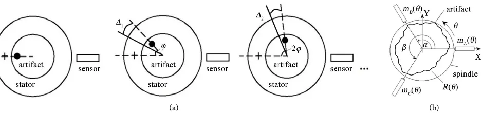
3.2. Multi-Position Method
When using multi-position method to separate roundness of the artifact and ro-tating the artifact by a constant angle ϕ, an angular error ∆i exists, as is shown in Figure 5(a). According to the principle introduced in [4], the mea-surement error induced by angular error ∆k is derived as
( )
(
)
(
)
(
)
( )
1 0 1 0 1 1 N k k N k k kE R k
N
R k R k
N
θ θ ϕ
θ ϕ θ ϕ ο
− = − = = + + ∆ ′ ≈ + + + ∆ + ∆
∑
∑
(17)As roundness of the artifact can be expressed as Fourier series and when N is an even integer, we have 1
(
)
0 0
N
k R θ kϕ
−
= + =
∑
. If ∆k is small enough, we have( )
1(
)
0
1 N
k k
E R k
N
θ − θ ϕ
= ′
≈
∑
+ ∆ (18)3.3. Multi-Probe Method
Three-probe method is detailed in [5], here gives only the formulas. Define
( )
M θ as linear combination of m1
( )
θ , m2( )
θ and m3( )
θ with coefficientsa, b and c respectively, namely
( )
( )
( )
( )
(
)
(
)
sin sin sin sinA B C
M m bm cm
b
c
θ θ θ θ
β β α α β α = + + = − − = − (19)
[image:6.595.213.535.64.166.2]DOI: 10.4236/wjet.2018.63034 573 World Journal of Engineering and Technology (a) (b)
Figure 5. Angular positioning error of multi-position (a) and three-probe methods (b).
(
)
sin sin
b= − β β α− , c=sinα sin
(
β α−)
. Applying discrete Fourier transformation (DFT) to formula (19) yields( )
(
1 e jk e jk)
( )
M k = +b − α+c − β R k (20)
when three-probe method is used, let angular position errors of probes at posi-tions
α
and β be δα and δβ respectively, as is shown in Figure 5(b). We have the measurement error of roundness of artifact in frequent domain( )
( )
1( )
2( )
1 1
1 1 1
x y
E k M k C S k C S k
W W W
= − − +
(21)
where W k1
( )
= +1 be−jk(α δα+ )+ce−jk(β δβ+ ),W k( )
= +1 be−jkα+ce−jkβ,(
)
(
)
1 1 bcos ccos
C = + α δα+ + β δβ+ , C2 =bsin
(
α δα+)
+csin(
β δβ+)
By inverse Fouries transformation we have the measurement error( )
(
( )
)
e θ =IDFT E k .
4. Summary
Factors influencing measurement error of radial error motion are discussed in detail. Nonlinearity of a capacitive displacement probe targeting a spherical sur-face is investigated through experiment and the phenomena of fake displace-ment induced by lateral offset of the probe relative to an artifact ball are dis-cussed. It is shown that the error motion in radial and axial direction and eccen-tric rotation of artifact ball will both induce lateral offset which causes a fake output of probes.
References
[1] Tauhiduzzaman, M. (2015) Form Error in Diamond Turning. Precision Engineering, 42, 22-36. https://doi.org/10.1016/j.precisioneng.2015.03.006
[2] Evans, C.J., Hocken, R.J. and Estler, W.T. (1996) Self-Calibration: Reversal, Redundancy, Error Separation, and Absolute Testing. CIRP Annals-Manufacturing Technology, 45, 617-634. https://doi.org/10.1016/S0007-8506(07)60515-0
[3] Zhang, G.X., Zhang, Y.H., Yang, S.M., et al. (1997) A Multipoint Method for Spindle Error Motion Measurement. CIRP Annals Manufacturing Technology, 46, 441-445.
https://doi.org/10.1016/S0007-8506(07)60861-0