Data Throughput Assessment of 4T4R MIMO Technique
on LTE Wireless Cellular Networks
Joseph M. Mom
Department of Electrical and Electronics Engineering, Federal University of Agriculture, Makurdi
George K. Azever
Department of Electrical and Electronics Engineering, Federal University of Agriculture, Makurdi
Moses S. Maor
Department of Electrical and Electronics Engineering, Federal University of Agriculture, Makurdi
ABSTRACT
Long Term Evolution (LTE) known as 4G technology is developed to solve exponential demand for higher data rate by the users. This research work carried out measurement on a captured LTE wireless network of a 4- way Transmit, 4-way Receive (4T4R) multiple-input multiple-output (MIMO) optimization technique and existing 2x2 MIMO to assess the throughput. The assessment was conducted on a mobile network set up of four sites and unit inter connection on LTE continuous coverage with inter-site distance of 500m using two terminals user equipment to download and upload data by drive test. Monitoring and results collection were carried out using Local monitoring Terminal (LMT) and Test mobile system (TEMs) Drive Test (DT) kit as well as analysis of data using TEMs DT kit and NetPerSec. The results showed that Terminal 1 recorded a maximum achievable downlink and uplink throughput of 47.5 Mbps and 14.2 Mbps respectively against the system baseline 2x2 MIMO of 33.6Mbps and 10.7Mbps respectively. Terminal2, on the other hand, achieved maximum downlink and uplink throughput of 44.0 Mbps and 14.1 Mbps respectively higher than the same baseline 2x2 MIMO. This improvement indicates that increasing the number of transmit and receive antennas expands the network capacity thereby yielding more throughput.
General Terms
LTE, Cellular Network, optimization technique, drive test.
Keywords
Throughput, Downlink, Uplink, MIMO, data rate.
1.
INTRODUCTION
Long Term Evolution (LTE) is the evolution of the Third-Generation (3G) of mobile communications that create a new radio-access technology which provide high data rates, low latency and high spectral efficiency [1]. Due to the new technologies that have inherent capacity for higher data rate
consumption, there is great need to optimize with basic features techniques. Since, network conditions and User Equipment (UE) capabilities differ greatly, a high degree of flexibility is required in order to have maximum throughput.
One of such solutions is the improvement of performance and spectral efficiency using MIMO technology, which is one of the main features of the LTE develop to improve data throughput and spectral efficiency above that obtained by the use of OFDM [2]. Although MIMO adds complexity to the system in terms of processing and the number of antennas required, it enables far high data rates to be achieved along with much improved spectral efficiency [3]. As a result, MIMO has been included as an integral part of LTE to enhances space dimension, network capacity, increase range
and improve reliability without additional bandwidth as well as increased transmit power [2], [4].
The aim of this study is to assess the impact of a 4x4 MIMO optimization technique on an existing 2x2 MIMO optimization technique on LTE network in term of data rate throughput.
2.
Mathematical formulation of 4x4 MIMO
The equations and parameters that are relevant for the mathematical computation of peak data rate using MIMO technologies of wireless cellular networks are discussed as follows:2.1
MIMO Channel Capacity
Wireless cellular networks with Single-Input-Single-Output (SISO) systems offer limited channel capacity. The capacity of such systems is given by Shannon capacity theorem in a mathematical form [5] as
(1) Where C = capacity, B= bandwidth of the systems, S/R = signal to noise ratio.
Therefore, MIMO systems are the one with multiple antennas at transmitting end and multiple antennas at receiving end. By using MIMO, these additional paths can be used to advantage to provide additional robustness to the radio link by improving the signal to noise ratio, or by increasing the link data capacity [2] [3].
The capacity of the MIMO systems for n transmitters and n receivers deriving from equation 1 are given by the relation (2)
Where, nT= number of transmitter antenna, nR= number of receiver antenna.
But, by applying space-time coding techniques where the signal is coded. The capacity of the MIMO systems is given ( 3)
Where, Min (nT, nR) = minimum of nT and nR
For the purpose of this work, 4x4 MIMO is used where nT=4 and nR =4.
2.2
MIMO Channel Model
is thus modeled with Equation (4) below. The variables are matrices of complex numbers rather than scalar numbers.
(4)
Where r and s are the received and transmit vectors, while H and n are the channel matrix.
3.
METHODOLOGY
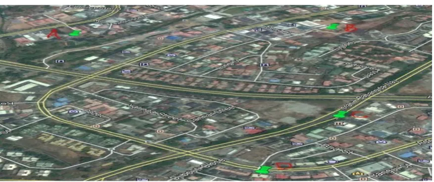
Four mobile network sites labelled A, B, C and D of a service provider were selected as shown in Appendix A (Figure 1). The test trial cluster was chosen based on LTE continuous coverage with inter-site distance of about 500m to reduce the impact on Multi path effect in the said cluster.
The Antenna setup of one-box 4-Port and radio Unit inter connection of same length Jumper Cables with an Engineering tolerance of ≤1m & 1Db is shown in Figure 2. Two terminals, Terminal 1 and Terminal 2 which are User Equipment (UEs) were used to download and upload data. The choice of the terminals was based on, Terminal 1 (Sony Z5 Ultra (QualcommSnapdragon 820)) is the World 1st 4x4 MIMO
Phone [6] supported by a 4x4 MIMO. Whereas Terminal 2 (Huawei B618) with features Such as 4G LTE speeds up to 600 Mbps, WiFi for 64 devices at a time, Wireless-AC WiFi speeds up to 1300 Mbps, 2 LAN ports (including 1 WAN / LAN), 1 RJ11 port for phone, printer or fax, 1 Micro SIM card slot (Dual-Free), 2 External Aerial Ports (TS-9), 1 USB 2.0 Port,Huawei HiLink App and Weight of 700 grams [7].
The similarity and difference in the behavior of the terminals were checked under controlled radio conditions. The behavior of the data streams was monitored using network Local monitoring Terminal (LMT).The results werecollected using TEMs drive test Kit and analyzed via DT tool and NetPerSec, a universal internet tool for data speed test [8].
For the purpose of validation, the same methodology was adopted for existing 2x2 MIMO with test UE (Huawei E5375). HUAWEI E5375 Hotspot is an LTE Cat4 and WiFi 2×2 technology with maximum download speeds of up to 150Mbps [9].
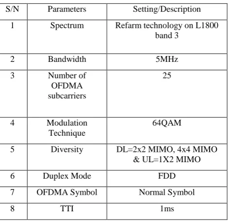
[image:2.595.306.555.334.487.2]Network Characteristics of the trial cluster on which study was conducted are depicted in Table 1.
Table 1: Network Characteristics of the trial cluster
S/N Parameters Setting/Description 1 Spectrum Refarm technology on L1800
band 3
2 Bandwidth 5MHz
3 Number of
OFDMA subcarriers 25 4 Modulation Technique 64QAM
5 Diversity DL=2x2 MIMO, 4x4 MIMO
& UL=1X2 MIMO
6 Duplex Mode FDD
7 OFDMA Symbol Normal Symbol
8 TTI 1ms
The maximum achievable DL/UP throughput, receive diversity and radio parameters results captured on TEMs drive test kit for 2x2 MIMO and 4x4 MIMO are shown in the Appendices B, C,D and E respectively and the discussion of results are presented section 5
.
4.
RESULTS AND DISCUSSIONS
The discussions are centered on the drive test on 2x2 MIMO used as baseline and 4x4 MIMO of the two Terminals 1 and 2achievable data throughput results obtained. The results of captured throughput results,4 streams of data during the test for verification (4-way receive diversity) and radio parameters captured during the study are shown in the appendix. The assessment of the study was done to certain the impact of MIMO technology on data rate (throughput) improvement in LTE deployment
.
4.1
MIMO Throughput Results
The maximum achievable downlink and uplink throughput results evaluated for 2x2 MIMO with Huawei E5375 Hotspot and 4x4 MIMO for Terminal 1 and 2 as UEs are extracted from Appendices B, C and D were computed as presented in Table 2.
Table 2: Results obtained for Analysis
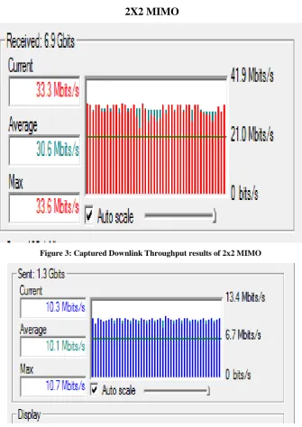
S/N Test UE MIMO used Max.DL throughput (Mbps) Max.UL throughput (Mbps) 1 Huawei E5375 2x2 MIMO 33.6 10.7
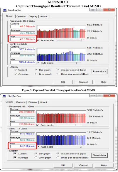
2 Terminal 1 4x4 MIMO
47.5 14.2
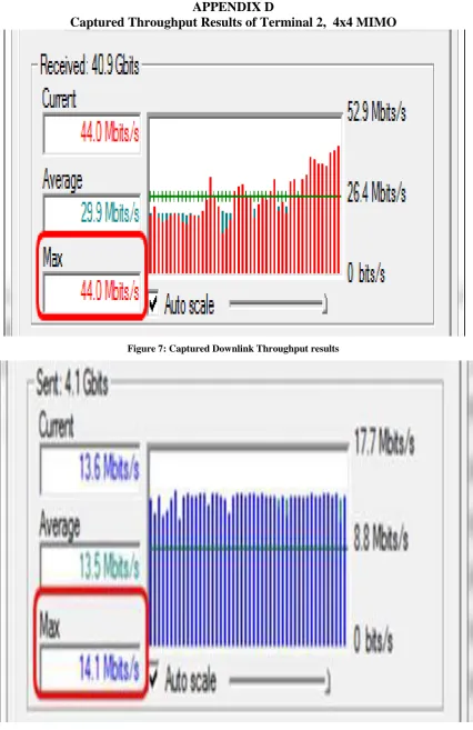
3 Terminal 2 4x4 MIMO
44.0 14.1
4.1.1
Results of Terminal 1Throughput Obtained
From the results of Table 2 for Terminal 1, maximum downlink throughput achieved was 47.5Mbps. This represented about 29.3% increase from the baseline 33.6Mbps of2x2 MIMO techniques used on the Network. Whereas maximum uplink throughput achieved was 14.2Mbps. This represented about 32.7% increase from the existing 10.7Mbps of 2x2 MIMO technique used on the Network. This indicates that increasing the number of transmitters and receivers of antennas enhance the network capacity thereby increase data throughput of the network.
4.1.1.1
Results of Terminal 2 Throughput
Obtained
[image:2.595.51.288.538.766.2]4.1.1.2
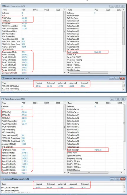
Results of Radio Parameters
Figure 8 in Appendix D, shows excellent radio conditions and parameters during the study as defined in [10]. It is observed that RSRP and RSRQ were maintained at a mean value of -68.00 dBm and -13.00 dBm respectively. This represents a very good radiocondition ofthe captured network. Maximum RANK Indicator was also achieved (RANK 3). Ranking is done from 0 to 3, hence RANK 3 implies that all the four data streams were used in the study.
5.
CONCLUSION AND
RECOMMENDATIONS
The research work has established great improvement in user throughput using two capable UEs on a 4x4 MIMO technique as compared to the existing 2x2 MIMO technique.
By using this technique, Network Operators would:
1. Improve Max UL throughput by 32.7% (10.6 Mbps to 14.2 Mbps) and Max DL throughput by 29.3% (33.6 Mbps to 47.5 Mbps) respectively using Terminal 1.
2. Improve MaxUL throughput by 23.7% (10.6Mbps to 14.1 Mbps) and Max DL throughput by 24.1% (33.6 Mbps to 44 Mbps) using Terminal 2
Hence, this improvement has demonstrated the efficiency of the technique through drive test measurement. This technique would absolutely increase user speed thereby enhancing system capacity and improving average quality of cellular network system.
It is therefore recommended that cellular network service providers should adopt this strategy in enhancing data speed using LTE so as to improve and enhance subscriber experience.
6.
ACKNOWLEDGMENTS
The Authors thank all those who have contributed towards success of this research work.
7.
REFERENCES
[1] Tshiteva, D .and Anthony,L. 2011.Downlink Scheduling in 3GPP Long Term Evolution (LTE). Wireless and mobile Communication (WMC)Group Faculty of Electrical Engineering, Mathematics and Computer Science, Delft University of Technology.
[2] Olabode, B. I., Augustus, E. I., Atayero, A.A. 2017.MIMO Optimization Techniques and Their Application in Maximizing Throughput for3GPP HSPA+.Scientific & Academic Publishing, Electrical& Information Engineering Dept Covenant University, Ota, ‘Nigeria.
[3] Evans, B. G., and Baughan, K., 2002. Visions of 4G," Electronics and Communication Engineering Journal.12(6): pp 293-303.
[4] Praveen, V. and Sven, N. 2016. Maximizing LTE performance with MIMO systems. Master Thesis in Electrical Engineering,Linnaeus University Sweden. [5] Kritika, S., Nishu, R., Ankita, S., Dolly, S., Seema, V.,
Tanya, S. 2014. Study and Capacity Evaluation of SISO, MISO and MIMO RF Wireless Communication Systems. International Journal of Engineering Trends and Technology (IJETT) – 9(9); pp 436-440.
[6] Mobile World Congress (MWC). 2016. World 1st 4x4 MIMO Phone, Sony Z5 Ultra (NGTUE).
(QualcommSnapdragon 820).
[7] https://www.4gltemall.com/blog/tag/huawei-b618-review/. Released on 19th March, 2018.
[8] https://www.academia,edu/675747/LTE_Drive_Test_Pro cedure. Downloaded on 10th January, 2019.
[9] https://www.4gltemall.com/blog/tag/huawei-e5375/. Released on 16th July, 2013.
[10] Harish, M. 2016. LTE Drive Test Parameters. Post Graduate Diploma in Management at Great Lakes Institute of Management. http//www.lte drives test parameters.com.
8.
APPENDIX A
[image:3.595.81.520.561.745.2]Site selection and Antenna & Radio Unit layout for the Study
Figure 2: Antenna and Radio Unit layout
APPENDIX B
[image:4.595.130.466.282.757.2]2X2 MIMO
Figure 3: Captured Downlink Throughput results of 2x2 MIMO
Figure 4: Captured Uplink Throughput results of 2x2 MIMO
A
Radio Unit
+45°
-45°
+45°
-45°
APPENDIX C
[image:5.595.98.501.72.659.2]Captured Throughput Results of Terminal 1 4x4 MIMO
Figure 5: Captured Downlink Throughput Results of 4x4 MIMO
APPENDIX D
[image:6.595.87.514.73.731.2]Captured Throughput Results of Terminal 2, 4x4 MIMO
Figure 7: Captured Downlink Throughput results