Modelling Study Of Supercritical Power Plant And Parameter Identification
Using Genetic Algorithms
Omar Mohamed, Jihong Wang, Shen Guo,Bushra Al-Duri, Jianlin Wei
Abstract—The paper aims to study the whole process mathematical model for a supercritical coal-fired power plant. The modeling procedure is based on thermodynamic and engineering principles and the previously published literatures. Model unknown parameters are identified using Genetic Algorithms (GAs) with 600MW supercritical power plant on-site measurement data. The identified parameters are verified with different sets of measured plant data. Although some assumptions are made in modeling process, the supercritical coal-fired power plant model reported in the paper can be used to simulate the main features of the real plant once-through boiler operation and the simulation results show the main variation trends of the process.
Index Terms— coal-fired power generation, Genetic Algorithms, mathematical modeling, supercritical boiler.
NOMENCLATURE
ff Fitness function.
ffr Fuel flow rate (Kg/s).
h Enthalpy per unit mass (MJ/Kg).
K Constant.
k Mass flow rate gain.
MW MW power generated.
m Mass (Kg).
m& Mass flow rate (Kg/s).
P Pressure of a heat exchange (MPa).
Q& Heat transfer rate (MJ/s).
R
Response
T Temperature (Cº).
t Time (sec).
τ Time constant (sec).
U Internal energy (MJ).
V Volume of fluid (
m
3).W& Work rate or power (MW).
x State vector.
y Output vector.
l Intermediate variables vector
℘ Input vector.
ρ Density (Kg/
m
3).ℵ Valve opening.
ε
Efficiency.
Subscripts: ec Economizer
hp High pressure turbine
hx
Heat exchanger
i Inlet
ip Intermediate pressure turbine
ms Main steam
m
Measured
o
Outlet
out Output of turbine
rh
Reheater
sh
Superheater
si
Simulated
ww Waterwall
Abbreviations:
ECON Economizer GA Genetic algorithm HP High pressure HX Heat exchanger IP Intermediate pressure RH Reheater
SC Supercritical SH Superheater WW Waterwall
I .INTRODUCTION
The world is now facing the challenge of global warming and environment protection. On the other hand, the demand of electricity is growing rapidly due to economic growth and increases in population. With the consideration of environmental issues and sustainable development in energy, renewable energy such as wind, solar, and tidal wave should be only resources to be explored in theory. But the growth in demand is also a heavy factor in energy equations so the renewable energy alone is not able to generate enough electricity to fill the gap within a short time of period. Power generation using fossil fuels is inevitable, especially, coal fired power generation is found to be an unavoidable choice due to its huge capacity and flexibility in load following ([1], [2]).
The conventional coal fired power plants have a huge environmental impact and lower energy conversion efficiencies. Any new coal fired power plants must be cleaner compared with traditional power plants. Supercritical power plants are the most suitable choice with consideration of the factors in environmental enhancement, higher energy efficiency and economic growth. However, there has been an issue to be addressed to adopt this technology in the UK because the dynamic response and performance still require study for better understanding supercritical plants in relation with conventional subcritical plants, and the supercritical units are considered by others to be unreliable in comparison with subcritical units [3]. Therefore, the characteristics of supercritical plants remain to be considered and investigated. Supercritical boilers have to be once-through type boilers because there is not distinction between water and steam phases in supercritical process so there is no need for drum to separate water steam mixture. Due to the
Omar Mohamed, Jihong Wang*, Shen Guo, Jianlin Wei are with the
School of Electronic, Electrical and Computer Engineering, the University of Birmingham, Edgbaston, Birmingham B15 2TT, UK Bushra Al-Duri is with the School of Chemical Engineering, University of Birmingham, Edgbaston, Birmingham B15 2TT, UK
* The author for correspondence.
absence of the drum, the once-through boilers have less stored energy and faster response than the drum boiler plants. However, there are several advantages of supercritical power plants over traditional subcritical plants include:
• Reduced fuel cost due to improved plant efficiency.
• Significant improvement of environment by reduction in CO2 emissions.
• Plant costs less than subcritical technology costs and other coal technologies.
• Can be fully integrated with appropriate CO2 capture technology.
•
Fast response due to load changes and high capacity which make them suitable for base load operation, and also for fast load demand following.From the literature survey, it has been found that several models have been reported with emphasis on different aspects of the boiler characteristics. Studying the response and control performance of once through supercritical (SC) units began on 1958 when work was started on a simulation of the Eddystone I unit of Philadelphia Electric Company and the work was extended for simulation of Bull run SC generation unit ([4], [5]). Yutaka Suzuki et al. modelled a once through SC boiler in order to improve the control system of an existing plant. The model was based on nonlinear partial differential equations, and the simulation results indicated that the model is valid ([6]). Wataro Shinohara et al. (1996) presented a simplified state space model for SC once through boiler-turbine and designed a nonlinear controller [7]. Pressure node model description was introduced by Toshio Inoue et al. for power system frequency simulation studies [8]. Intelligent techniques contributions have yielded an excellent performance for modeling. Neural network has the ability to model the SC power plant with sufficiently accurate results if they are trained with suitable data provided by operating unit [9]. However, neural network performances are unsatisfactory to simulate some emergency conditions of the plant because NN method depends entirely on the data not on physical laws. Simulation of SC boilers may be achieved either theoretically based on physical laws or empirically based on experimental work. In this paper, the proposed mathematical model is based on thermodynamic principles and the model parameters are identified according to a 600MW SC power plant operating currently in China. The simulation results show that the model is trustable to simulate the whole once-through mode of operation.
II. MATHEMATICAL MODEL OF THE PLANT
A. Plant description
The unit of a once-through supercritical 600MW power plant is selected for the modelling study. The schematic view of the boiler is shown in Fig.1. Water from the feedwater heater is heated in the economizer before entering the superheating stages through the waterwall. The superheater consists of three sections which are low temperature superheater, platen superheater, and final stage superheater. The main steam outlet temperature is about 571Cº at the steady state and a pressure is 25.5 MPa. There are 2 reheating sections in the boiler for reheating
the reduced thermal energy steam exhausted from the high pressure turbine. The inlet temperature of the reheater is 309 Cº and the outlet temperature is nearly 571 Cº and average pressure is 4.16MPa. The reheated steam is used to energize the intermediate pressure turbine. Finally, the mechanical power is generated through multi-stage turbines to provide an adequate expansion of the steam through the turbine and subsequently high thermal efficiency of the plant.
Fig.1. schematic view of the plant
B. Assumptions
Assumptions which are stated to simplify the process should be logically acceptable and sufficient to transfer the model from its complex physical state to simple mathematical state. A great attention should be taken for the choice of assumptions because some assumptions result in over-simplification and nonrelaistic system. For successful mathematical modeling, the following general assumptions are made:
• Fluid properties are uniform at any cross section, and the fluid flow in the boiler tubes is one-phase flow.
• In the heat exchanger, the pipes for each heat exchanger are lumped together to form one pipe.
• Only one control volume is considered in the waterwall.
• The dynamic behaviour of the air and gas pressure is neglected.
• Only the change in internal energy is considered, the deviations or changes of kinetic energy and potential energy of fluid are neglected.
C. Heat Exchanger model
The various heat exchangers in the boiler are modelled by mass and energy balances. The sub-cooled water in the economizer is transferred directly to a supercritical steam through the waterwall without passing with the evaporation status.. The equations are converted in terms of the derivatives pressure and temperature of the heat exchanger. Refer to Appendix A for the nomenclature and abbreviations. The mass balance equation of the heat exchanger (control volume) is:
o
i m
m dt dm
& & −
= (1)
o
i m
m dt d
V ρ = & −&
The density is a differentiable function of two variables which can be the temperature and pressure inside the control volume, thus we have:
o i P T m m dt dT T dt dP P
V = & − &
∂ ∂ + ∂ ∂ ) . .
( ρ ρ
The energy balance equation:
o o i i hx
hx Q mh mh
dt dU
& & & + − = Also dt dP V ) dt dT . T h dt dP . P h ( ) dt dT . T dt dP . P ( h V dt dU P T P T hx − ⎥ ⎦ ⎤ ∂ ∂ + ∂ ∂ ⎢ ⎣ ⎡ + ∂ ∂ + ∂ ∂ = ρ ρ ρ
Then, the energy balance equation becomes:
o o i i hx P T P T h m h m Q dt dP V ) dt dT . T h dt dP . P h ( ) dt dT . T dt dP . P ( h V & & & + − = − ⎥ ⎦ ⎤ ⎢ ⎣ ⎡ ∂ ∂ + ∂ ∂ + ∂ ∂ + ∂
∂ρ ρ ρ
(2)
Solving (1) and (2) to get the pressure and temperature state derivatives, τ H m H m Q
P&= &hx+&i i−&o o (3)
P D m m C
T&= (&i− &o)− & (4) where: ) T T h h h ( H P P i i ∂ ∂ ∂ ∂ − − = ρ ρ
(5) ) T T h h h ( H T P o o ∂ ∂ ∂ ∂ − − = ρ ρ
(6) ) T T h . P P h ( V P P T T 1 − ∂ ∂ ∂ ∂ ∂ ∂ − ∂ ∂ = ρ ρ ρ ρ τ (7) P T V C ∂ ∂ = ρ 1 (8) P T T P D ∂ ∂ ∂ ∂ = ρ ρ (9)
The temperature of the superheater is controlled by the attemperator. Therefore, the input mass flow rate to the superheater is the addition of the SC steam and the water spray from the attemperator. The amount of attemperator water spray is provided by opening the spray valve which
responds to a signal from PI controller. This prevents the temperature high fluctuation and ensures maximum efficiency over a wide range of operation.
D. Fluid flow
The fluid flow in boiler tubes for one-phase flow is:
P k
m& = . Δ (10)
Which is the simplist from for fluid flow in boiler tubes. The flow out from the reheater and main steam respectively are: rh rh rh rh T P K
m& = 1′⋅ ⋅ℵ (11)
ms ms ms ms T P K
m& = 2′⋅ ⋅ℵ (12)
The detailed derivation of (11), and (12) can be found in [10].
E. Turbine / Generator Model
The turbine and generator can be modelled only by energy balance equation. The boiler response is very slow compared with turbine/ generator responses. Therefore, there is no need to detail the model of the turbine/generator as in the case of SC boiler. The turbine energy balance equation:
hp out ms
ms.(h h ) W
m& − = &
(13)
ip out ms
rh.(h h ) W
m& − = & (14)
The generated power of the plant:
) W W (
MW =ε &hp+ &ip (15)
F. Heat transfer rate
The combustion heat transfer rate is a first order lag of the fuel flow rate ([8], [11]). The heat transfer rates of the various heat exchangers are directly proportional to the main combustion heat transfer rate. This greatly simplifies the mathematical model without sacrificing the important dynamics to be considered for the plant.
ffr s Q 1 1 1 τ + = & (16) Q ec K ec
Q& = & (17)
Q K
Q&ww= ww& (19)
Q K
Q&sh= sh& (20)
Q K
Q&rh= rh& (21)
G. Final form of the model
x&1= f(x1,℘,l) (22)
) , , x ( f
x&2 = 1℘ l (23)
) , , x , x ( f
y= 1 2℘l (24)
are the intermediate mass flow rates of fluid. The output vector
y
can be taken as any variable from the vectors1
x and x2 since the model is implemented in MATLAB / SIMULINK, the observation of any variable dynamics is available at any point in the model.
III. MODEL PARAMETER IDENTIFICATION
A. Data selection:
The data should be informative for successful identification procedures. The once-through operation of the plant starts nearly above 30% of rated load (Fig.2.). The behaviour of the plant during start-up is completely different from that of the once-through mode because the separator separate the water from steam during start-up process and the water is re-circulated for further heat addition. After start-up process is completed, the circulation valve closes to allow the once-through operation. Therefore, the model for the boiler during start-up is different from the once-through mode model and the start-up data shouldn't be used for identification of the proposed model parameters. Only the data of once-through operation is used for the identification and verification
B. Identification procedures:
The parameters of the model which are defined by from (5) to (9) and the other parameters of mass flow rates’ gains , heat transfer constants, turbine/generator parameters are all identified by genetic algorithm. Even though some of these parameters can be found from the properties of water/steam or steam table and thus they are inherently not constant, but these parameters are fitted directly to the actual plant response to save time and effort. Various boiler responses have been chosen for identification and verification. First, the parameters of pressure derivatives equations are indentified. Secondly, the identification is extended to include the temperature equations and turbine/generator model.
Fig.2. Power survey for the modelled 600MWSC plant Over more than 24hrs
The responses which are chosen for identification and verification are:
• Reheater pressure.
• Main SC steam pressure.
• Main SC steam temperature.
• Mass flow rate of SC steam from boiler main outlet to HP turbine.
• Mass flow rate of reheated steam from reheater outlet to the IP turbine.
• Generated power of the plant.
In recent years, Genetic Algorithms optimisation tool has been widely used for nonlinear system identification and optimization ([12], [13], [14]). This is because it has many advantages over conventional mathematical optimization techniques. It has been proved that the GA tool is a robust optimization method for parameters identification of subcritical boiler models [11] and Tube Ball mills ([15]). Initially, the GA produces a random initial population. Then, it calculates the corresponding fitness function to recopy the best coded parameter in the next generation.. The GA termination criteria depend on the value of the fitness function. If the termination criteria is not met, the GA continue to perform the three main operations which are reproduction, crossover, and mutation. More details about this technique can be found in the text of David Goldberg 1989 [16]. The fitness function for the proposed model is:
2
1
) R R (
ff N si
n
m−
=
∑
=
(25)
which is the sum of the square of the difference between measured and simulated responses for each of the variables mentioned in this section. N is the number of points of the recorded measured data, The identification scheme is shown in Fig.3. The load-up data have been used for identification from 30% to 100% of load. The next step is to verify the proposed model. The model is verified from load down from 100% to 55% and steady state data to cover the large range of once-through operation. The GA parameters for identification of optimal parameter of the model are mentioned below:
Population type: double vector Creation function: uniform Population size: 50 Mutation rate: 0.1 Mutation function: Gaussian Migration direction: forward Selection: stochastic uniform Crossover function: scattered
Fig.3. schematic diagram of model's parameter
identification
well matched; the simulated main steam pressure and main steam temperature responses are also reasonably matched. There are so many parameters in the model so we cannot mention them all. The optimal parameters of the heat exchanger model are mentioned in Table 1 and for heat transfer rates are mentioned in Table 2.
Table 1. Heat exchanges' parameters
HX Hi Ho C D
ECON 10.2 13.6 2.1e-6 -3.93 WW 12.2 13.3 -1.2e-6 -0.1299
SH 20.5 45.9 1e-6 -3.73 RH 19.8 22. -1e-6 -17.9
Table 2. Heat transfer rate parameters 1
τ (s) Kec Kww Ksh Krh
9.3 5.7785 7.78 23.776 21.43
0 100 200 300 400 500
0 100 200 300 400 500 600 700
Time (min)
P
o
w
er (M
W
)
Plant response Model response
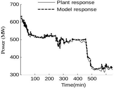
Fig.4 Power response for plant and Model
0 100 200 300 400 500 0
5 10 15 20 25 30
Time (min)
m
ai
n
s
team
p
re
ss
u
re
(M
Pa
)
Plant response Model response
Fig.5 Load-up main steam pressure response
0 100 200 300 400 500 600
530 540 550 560 570
Time (min)
T
em
p
er
at
ur
e (
C
)
Model response Plant response
Fig.6 Load-up main steam temperature
0 100 200 300 400 500
0 100 200 300 400 500
Time (min)
m
ai
n
st
eam
f
low
(
K
g/
s)
Plant response Model response
Fig.7 Load-up main steam flow
IV. MODEL VERIFICATION
The validation of the proposed model has been performed on the variables mentioned in section. III by a number of data sets which are the load down and steady state data. Figs.8, 9, and 10 demonstrate the reheater pressure and power for steady state operation. Also, the main steam flow rate and power for load down operation are shown in fig.6. From the results mentioned, it is obvious that the model response and the actual plant response are very well agreed for the power, reheater pressure and steam flow rate. Thus the model is valid for steady state and load change conditions and it will be very useful for control synthesis.
100 200 300 400 500
300 400 500 600 700
Time(min)
Pow
er
(
M
W
)
Plant response Model response
[image:5.595.41.289.132.450.2] [image:5.595.347.535.582.729.2]0 200 400 600 800 0
1 2 3 4 5
Time(min)
R
eheat
er
pr
essur
e (
M
Pa)
Plant response Model response
Fig.9 Steady state reheater pressure
0 200 400 600 800
0 100 200 300 400 500
Time(min)
M
ai
n
S
C
s
te
am
f
lo
w
(
K
g
/s
)
Plant response Model response
Fig.10 steady state steam flow rate
V. CONCLUDING REMARKS
A model of coal fired power generation with supercritical boiler has been presented. The model is based on thermodynamic laws and identified according to operating data record. The model is also verified by different data sets and the simulation results show that the model is valid. As a future work, the model will be combined with a nonlinear mathematical model of coal mill to obtain a wide mathematical model for the whole process from coal grinding to electricity generation. In addition, a further study will be carried out to improve the plant response by control system design.
ACKNOWLEDGEMENT
The authors would like to thank the Libyan Cultural Affairs for the Scholarship and also give their thanks to EPSRC(EP/G062889) and E.ON for their research funding support. The author also wish to express their sincere appreciation to Professors Junfu Lv and Qirui Gao from Tsinghua University for their contribution.
REFERENCES
[1] F. Laubli, and F. H. Fenton, “The Flexibility of The Supercritical Boiler as A Partner in Power System Design and Operation: Part I” IEEE Transactions on Power
Apparatus and Systems, vol PAS-90, No. 4, 1971, pp.1719-1724 .
[2] F. Laubli, and F. H. Fenton, “The Flexibility of The Supercritical Boiler as A Partner in Power System Design and Operation: Part II” IEEE Transactions on Power
Apparatus and Systems, vol PAS-90, No. 4, 1971, pp.1725-1733.
[3] P. Kundur “A survey of utility experiences with power plant response during partial load rejection and system disturbances” ”. IEEE Transactions on Power Apparatus
and Systems, vol. PAS-100, No.5 , June 1981, pp.2471-2475
[4] J. Adams, D. R. Clark, J. R. Luis, and J. P. Spanbaur, “Mathematical Modelling of Once-Through Boiler Dynamics”, IEEE Transactions on Power Apparatus and Systems, vol 84, No. 4, Feb 1965, pp. 146-156.
[5] B. Littman, and T. S. Chen, “Simulation of bull-run supercritical generation unit”. IEEE Transactions on Power
Apparatus and Systems, vol. 85, 1966, pp.711-722. [6] W. Shinohara, and D. E. Kotischek, “A simplified model
based supercritical power plant controller”. Proceeding of
the 35th IEEE conference on decision and control,
vol .4 , 1995, pp. 4486-4491.
[7] Y. Suzuki and P. Sik, Y. Uchida “Simulation of once-through supercritical boiler”, SIMULATION, vol.33, 1979, pp. 181-193.
[8] T. Inoue, H. Taniguchi, and Y. Ikeguchi “A Model of Fossil Fueled Plant with Once-through Boiler for Power System Frequency Simulation Studies” IEEE Transactions
on Power Systems, vol. 15, No. 4, 2000, pp. 1322-1328. [9] K. Y. Lee, J. S. Hoe, J. A. Hoffman, H. K. Sung, and H.
J. Won, “Neural network based modeling of large scale power plant”. IEEE Power Engineering Society General
Meeting. No (24-28), 2007, pp. 1- 8.
[10] A. S. Leyzerovich "Steam Turbines for Modern Fossil-Fuel Power Plant". The Fairmont Press, Inc. 2007.
[11] A. Ghaffari, A. Chaibakhsh. “A simulated model for a once through boiler by parameter adjustment based on genetic algorithms” Simulation Model and Practice Theory, vol.15, August 2007, pp. 1029-1051.
[12] J. Wei, J. Wang, and Q. H. Wu, “Development of multisegment coal mill model using an evolutionary computation technique”. IEEE Transactions on energy
conversions, vol. 22, 2007, pp. 718-727.
[13] J. Wang, J.D. Wang, N. Daw, Q.H. Wu, “Identification of pneumatic cylinder friction parameters using genetic algorithms”, IEEE/ASME Transactions on Mechatronics, vol 9. No.1, 2004, pp.100-107.
[14] S. Mangan and J. Wang, “Development of a novel sensorless road gradient estimation method based on vehicle CAN Bus data”, IEEE/ASME Transactions on
Mechatronics, vol. 12, No.3, 2007, pp. 375-386.
[15] J. Wei, J. Wang, S. Guo, “Mathematic Modelling and Condition Monitoring of Power Station Tube-ball Mill Systems”, The Proceedings of AMERICAN CONTROL CONFERENCE, vols 1-9, 2009, pp. 4699-4704.