Abstract— In spite of inability to dynamically adapt to network topology failures and high management overhead, Static Routing still offers robustness to routing convergence failure, external route spoofing and easy prediction. This paper proposes a Static Routing strategy with an objective of extending its ability to adapt to logical network topology changes, equipment failures or network outages 'on the fly'. This strategy will involve discovery of all possible Static Routes from a specific source router to destination router, analyzing and ordering their applicability using optimality principle based Sink Tree approach. A random subnet composed of fifteen routers is simulated and mapped to Sink Tree and most obvious paths between random source and destination are analyzed. Static Routes are traced to extract information about hop count from source to destination. The hop count information is recorded for each Static Route trace and comparative analysis is performed. Based on this comparison the Static Route are sorted in order of preference as per optimality principle and are offered to router as secondary routes in event of failure of primary preferred Static Route, thereby retaining the benefits of Static Routing while still availing the flexibility of Dynamic Routing to some extent.
Index Terms— Backup Route, Floating Route,
Optimality Principle, Static Routing, Sink Tree.
I. INTRODUCTION
For over two decades now Dynamic Routing protocols have dominated the Networking Scenario throughout the world. The attribute of protocols like RIP,OSPF, IS-IS,IGRP/ EIGRP [1] to dynamically adapt to network topology changes or equipment failures along with low management overhead make them obvious choice for vast array of Network based applications. In context of above situation Static Routing face an upheaval task to maintain its credibility as a competitive alternative to Dynamic Routing. Never the less Static Routing have its inherent advantages such as simple configuration and easy prediction coupled with robustness against certain kinds of pathological network problems such as routing convergence failure [2] and external route spoofing [2]. Moreover since Static Routing is not really a protocol, there is no overhead of maintaining a distributed algorithm such as for
Manuscript received May 20, 2008.
H. S. Johal is Assistant Professor at Department of Computer Science and Information Technology, Lovely Institute of Technology, Lovely Professional University, Phagwara, 144402 INDIA (phone: 0919988231936; fax: 0911824506111; e-mail: [email protected]).
route calculation [3] as in case of most Dynamic Routing potocols. It is but natural to encounter a situation where an application demands to retain obvious benefits of Static Routing and still asking for some degree of flexibility and fault tolerance as offered by Dynamic Routing. With this perspective a lot of work has been done on concept of Backup Routes [4] and Floating Static Routes [4], [5]. The paper intends to explore the probability of integrating a limited degree of fault tolerance to Static Routing by offering multiple alternative routes somewhat similar to concept of Backup and Floating Static Routes but sorted on basis of optimality principle using a Sink Tree. In the event of failure of specific static route the second best preferred route is offered, since this route is generated based on optimality principle using a Sink Tree, it will be the most optimal path still available under current situation thereby allowing us add limited degree of flexibility in terms of fault tolerance to Static Routing.
II. STATICROUTEANALYSIS
A random Subnet consisting of fifteen routers having one or more than one connection links between them is used as case study for analysis of different Static Routes.
B A
D E C
F G J
I
H N
L
K O M
Fig.1 Subnet Consisting of 15 Routers
III. CREATINGIPADDRESSSTRUCTURE
Routers H and Router B are identified as source and destination routers respectively. As per subnet structure, there are three different routes available while travelling from H to B or either way around. These are H↔O↔N↔J↔C↔B, H↔E↔J↔C↔B and H↔D↔A↔B. Only Routers falling on all possible paths from H to B are configured.
Static Route Analysis Based Multiple Route
Configuration Scheme for Adaptive Static
Routing
IP Address Allocation Scheme Followed:
Router Link Interface IP
A→ B 0/0 192.168.19.1/24 A → F 0/1 192.168.20.1/24 A
A → D 0/2 192.168.21.1/24 B → A 0/0 192.168.19.2/24 B
B → C 0/1 192.168.22.1/24 C → B 0/0 192.168.22.2/24 C → J 0/1 192.168.23.1/24 C
C → I 0/2 192.168.24.1/24 D → A 0/0 192.168.21.2/24 D → H 0/1 192.168.25.1/24 D → G 0/2 192.168.26.1/24 D
D → I 0/3 192.168.27.1/24 J → C 0/0 192.168.23.2/24 J → N 0/1 192.168.28.1/24 J → E 0/2 192.168.29.1/24 J
J → I 0/3 192.168.30.1/24 N → J 0/0 192.168.28.2/24 N → O 0/1 192.168.31.1/24 N
N → M 0/2 192.168.32.1/24 O → N 0/0 192.168.31.2/24 O
O → H 0/1 192.168.33.1/24 H → O 0/0 192.168.33.2/24 H → E 0/1 192.168.34.1/24 H→ F 0/2 192.168.35.1/24 H
H→ D 0/3 192.168.25.2/24 E → H 0/0 192.168.34.2/24 E
E → J 0/1 192.168.29.2/24 IV. ANALYZING ROUTE H↔O↔N↔J↔C↔B B
A
D E C
F G J
I
H N
L
K O M
Fig. 2 Route H↔O↔N↔J↔C↔B
IP Route Codes: C - connected, S - static, I - IGRP, R - RIP, M - mobile, B – BGP D - EIGRP, EX - EIGRP external, O - OSPF, IA - OSPF inter area E1 - OSPF external type 1, E2 - OSPF external type 2, E – EGP i - IS-IS, L1 - IS-IS level-1, L2 - IS-IS level-2, * - candidate default U - per-user static route Static Route Configuration for Router H
S 192.168.31.0 [1/0] via 192.168.33.1 S 192.168.28.0 [1/0] via 192.168.33.1 S 192.168.23.0 [1/0] via 192.168.33.1 S 192.168.22.0 [1/0] via 192.168.33.1
C 192.168.33.0 is directly connected, Ethernet0/0 C 192.168.34.0 is directly connected, Ethernet0/1 C 192.168.25.0 is directly connected, Ethernet0/3
Static Route Configuration for Router O S 192.168.28.0 [1/0] via 192.168.31.1 S 192.168.23.0 [1/0] via 192.168.31.1 S 192.168.22.0 [1/0] via 192.168.31.1
C 192.168.31.0 is directly connected, Ethernet0/0 C 192.168.33.0 is directly connected, Ethernet0/1 Static Route Configuration for Router N
S 192.168.33.0 [1/0] via 192.168.31.2 S 192.168.23.0 [1/0] via 192.168.28.1 S 192.168.22.0 [1/0] via 192.168.28.1
C 192.168.28.0 is directly connected, Ethernet0/0 C 192.168.31.0 is directly connected, Ethernet0/1 Static Route Configuration for Router J
S 192.168.31.0 [1/0] via 192.168.28.2 S 192.168.33.0 [1/0] via 192.168.28.2 S 192.168.22.0 [1/0] via 192.168.23.1
C 192.168.23.0 is directly connected, Ethernet0/0 C 192.168.28.0 is directly connected, Ethernet0/1 C 192.168.29.0 is directly connected, Ethernet0/2 Static Route Configuration for Router C
S 192.168.28.0 [1/0] via 192.168.23.2 S 192.168.31.0 [1/0] via 192.168.23.2 S 192.168.33.0 [1/0] via 192.168.23.2
C 192.168.22.0 is directly connected, Ethernet0/0 C 192.168.23.0 is directly connected, Ethernet0/1 Static Route Configuration for Router B
S 192.168.23.0 [1/0] via 192.168.22.2 S 192.168.28.0 [1/0] via 192.168.22.2 S 192.168.31.0 [1/0] via 192.168.22.2 S 192.168.33.0 [1/0] via 192.168.22.2
C 192.168.19.0 is directly connected, Ethernet0/0 C 192.168.22.0 is directly connected, Ethernet0/1 Routing Table for Router B
Protocol Address Hardware Addr Interface Internet 192.168.19.2 000C.4809.8723 Ethernet0/0 Internet 192.168.22.1 000C.7040.3851 Ethernet0/1 Routing Table for Router H
Protocol Address Hardware Addr Interface Internet 192.168.33.2 000C.5000.3333 Ethernet0/0 Internet 192.168.34.1 000C.8416.5856 Ethernet0/1 Internet 192.168.35.1 000C.8659.5322 Ethernet0/2 Internet 192.168.25.2 000C.1801.2897 Ethernet0/3 Route Trace H→B
Tracing the route to 192.168.22.1 1 192.168.33.1 0 msec 16 msec 0 msec 2 192.168.31.1 20 msec 16 msec 16 msec 3 192.168.28.1 20 msec 16 msec 16 msec 4 192.168.23.1 20 msec 16 msec 16 msec 5 192.168.22.1 20 msec 16 msec * Route Trace B→H
Tracing the route to 192.168.33.2 1 192.168.22.2 0 msec 16 msec 0 msec 2 192.168.23.2 20 msec 16 msec 16 msec 3 192.168.28.2 20 msec 16 msec 16 msec 4 192.168.31.2 20 msec 16 msec 16 msec 5 192.168.33.2 20 msec 16 msec *
From To Trace Route Hop Count
No of Static Routes Configured for H = 4 No of Static Routes Configured for B = 4
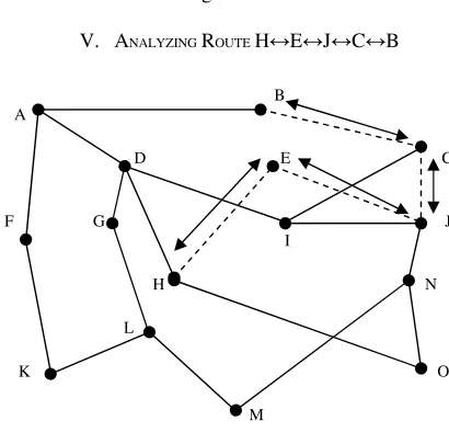
V. ANALYZINGROUTEH↔E↔J↔C↔B
B A
D E C
F G J
I
H N
L
K O M
Fig. 3 Route H↔E↔J↔C↔B
Static Route Configuration for Router H S 192.168.29.0 [1/0] via 192.168.34.2 S 192.168.23.0 [1/0] via 192.168.34.2 S 192.168.22.0 [1/0] via 192.168.34.2
C 192.168.33.0 is directly connected, Ethernet0/0 C 192.168.34.0 is directly connected, Ethernet0/1 C 192.168.25.0 is directly connected, Ethernet0/3 Static Route Configuration for Router E
S 192.168.23.0 [1/0] via 192.168.29.1 S 192.168.22.0 [1/0] via 192.168.29.1
C 192.168.34.0 is directly connected, Ethernet0/0 C 192.168.29.0 is directly connected, Ethernet0/1 Static Route Configuration for Router J
S 192.168.34.0 [1/0] via 192.168.29.2 S 192.168.22.0 [1/0] via 192.168.23.1
C 192.168.23.0 is directly connected, Ethernet0/0 C 192.168.29.0 is directly connected, Ethernet0/2 C 192.168.28.0 is directly connected, Ethernet0/1 Static Route Configuration for Router C
S 192.168.29.0 [1/0] via 192.168.23.2 S 192.168.34.0 [1/0] via 192.168.23.2
C 192.168.22.0 is directly connected, Ethernet0/0 C 192.168.23.0 is directly connected, Ethernet0/1 Static Route Configuration for Router B
S 192.168.23.0 [1/0] via 192.168.22.2 S 192.168.29.0 [1/0] via 192.168.22.2 S 192.168.34.0 [1/0] via 192.168.22.2
C 192.168.19.0 is directly connected, Ethernet0/0 C 192.168.22.0 is directly connected, Ethernet0/1 Routing table for Router B
Protocol Address Hardware Addr Interface Internet 192.168.19.2 000C.4809.8723 Ethernet0/0 Internet 192.168.22.1 000C.7040.3851 Ethernet0/1 Routing table for Router H
Protocol Address Hardware Addr Interface Internet 192.168.33.2 000C.5000.3333 Ethernet0/0 Internet 192.168.34.1 000C.8416.5856 Ethernet0/1 Internet 192.168.35.1 000C.8659.5322 Ethernet0/2 Internet 192.168.25.2 000C.1801.2897 Ethernet0/3
Route Trace H→B
Tracing the route to 192.168.22.1 1 192.168.34.2 0 msec 16 msec 0 msec 2 192.168.29.1 20 msec 16 msec 16 msec 3 192.168.23.1 20 msec 16 msec 16 msec 4 192.168.22.1 20 msec 16 msec * Route Trace B→H
Tracing the route to 192.168.34.1 1 192.168.22.2 0 msec 16 msec 0 msec 2 192.168.23.2 20 msec 16 msec 16 msec 3 192.168.29.2 20 msec 16 msec 16 msec 4 192.168.34.1 20 msec 16 msec *
From To Trace Route Hop Count
H B H → E → J → C → B 4 B H B → C → J → E → H 4 No of Static Routes Configured for H = 3
No of Static Routes Configured for B = 3 VI. ANALYZINGROUTEH↔D↔A↔B
B A
D E C
F G J
I
H N
L
[image:3.612.75.280.68.265.2]K O M
Fig. 4 Route H↔D↔A↔B
Static Route Configuration for Router H S 192.168.21.0 [1/0] via 192.168.25.1 S 192.168.19.0 [1/0] via 192.168.25.1
C 192.168.33.0 is directly connected, Ethernet0/0 C 192.168.34.0 is directly connected, Ethernet0/1 C 192.168.25.0 is directly connected, Ethernet0/3 Static Route Configuration for Router D
S 192.168.19.0 [1/0] via 192.168.21.1
C 192.168.21.0 is directly connected, Ethernet0/0 C 192.168.25.0 is directly connected, Ethernet0/1 Static Route Configuration for Router A
S 192.168.25.0 [1/0] via 192.168.21.2
C 192.168.19.0 is directly connected, Ethernet0/0 C 192.168.21.0 is directly connected, Ethernet0/2 Static Route Configuration for Router B
S 192.168.21.0 [1/0] via 192.168.19.1 S 192.168.25.0 [1/0] via 192.168.19.1
C 192.168.19.0 is directly connected, Ethernet0/0 C 192.168.22.0 is directly connected, Ethernet0/1 Routing Table for Router B
Internet 192.168.22.1 000C.7040.3851 Ethernet0/1 Routing table for Router H
Protocol Address Hardware Addr Interface Internet 192.168.33.2 000C.5000.3333 Ethernet0/0 Internet 192.168.34.1 000C.8416.5856 Ethernet0/1 Internet 192.168.35.1 000C.8659.5322 Ethernet0/2 Internet 192.168.25.2 000C.1801.2897 Ethernet0/3 Route Trace H→B
Tracing the route to 192.168.19.2 1 192.168.25.1 0 msec 16 msec 0 msec 2 192.168.21.1 20 msec 16 msec 16 msec 3 192.168.19.2 20 msec 16 msec * Route Trace B→H
Tracing the route to 192.168.25.2 1 192.168.19.1 0 msec 16 msec 0 msec 2 192.168.21.2 20 msec 16 msec 16 msec 3 192.168.25.2 20 msec 16 msec *
From To Trace Route Hop Count
H B H → D → A → B 3
B H B → A → D → H 3
No of Static Routes Configured for H = 2 No of Static Routes Configured for B = 2
VII. SINKTREE
B B B C C A
J J E N D O
H H H
[image:4.612.320.525.46.205.2](a) (b) (c)
Fig. 5 Sink Trees for Primary {3 hop depth} (a), Secondary {4 hop depth} (b), & Tertiary {5 hop depth} (c)
Routes.
Sorted Routes between H & B based on Optimality Principle
Trace Route Hop Count
Route Classification
H ↔ D ↔ A ↔ B 3 Primary Route H ↔ E ↔ J ↔ C ↔ B 4 Secondary Route H ↔ O ↔ N ↔ J ↔C ↔B 5 Tertiary Route Depth of n node Sink Tree = n–1
Hop Count for n Router path = n–1
Number of Static Routes need to be configured at Source and Destination for n node Sink tree = n–2 (Hop Count for n Router path – 1)
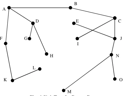
Optimality Principle [6] based Sink Tree [7] for Router B proposing most optimal paths from any Router in the subnet.
B A
D E C
F G J
I
H N
L
K O M
Fig. 6 Sink Tree for Router B
VIII. CONFIGURINGMULTIPLESTATICROUTES
With reference to above Static Route analysis we are able to grade Static Routes in preference with respect to optimality principle. These Multiple Static Route Configurations (MSRCs) are now offered to all the routers falling in all possible paths between H & B.
Routers falling on different classified static routes and requiring Multiple Static Route Configurations are listed. Primary Static Route Configuration for Router H S 192.168.21.0 [1/0] via 192.168.25.1 S 192.168.19.0 [1/0] via 192.168.25.1
C 192.168.33.0 is directly connected, Ethernet0/0 C 192.168.34.0 is directly connected, Ethernet0/1 C 192.168.25.0 is directly connected, Ethernet0/3 Secondary Static Route Configuration for Router H to be activated in case of failure of Primary Router/Link. S 192.168.29.0 [1/0] via 192.168.34.2
S 192.168.23.0 [1/0] via 192.168.34.2 S 192.168.22.0 [1/0] via 192.168.34.2
C 192.168.33.0 is directly connected, Ethernet0/0 C 192.168.34.0 is directly connected, Ethernet0/1 C 192.168.25.0 is directly connected, Ethernet0/3 Tertiary Static Route Configuration for Router H to be activated in case of failure of Secondary Route/Link. S 192.168.31.0 [1/0] via 192.168.33.1
S 192.168.28.0 [1/0] via 192.168.33.1 S 192.168.23.0 [1/0] via 192.168.33.1 S 192.168.22.0 [1/0] via 192.168.33.1
C 192.168.33.0 is directly connected, Ethernet0/0 C 192.168.34.0 is directly connected, Ethernet0/1 C 192.168.25.0 is directly connected, Ethernet0/3 Primary Static Route Configurations for Router D S 192.168.19.0 [1/0] via 192.168.21.1
C 192.168.21.0 is directly connected, Ethernet0/0 C 192.168.25.0 is directly connected, Ethernet0/1 Primary Static Route Configurations for Router A S 192.168.25.0 [1/0] via 192.168.21.2
C 192.168.19.0 is directly connected, Ethernet0/0 C 192.168.21.0 is directly connected, Ethernet0/2 Primary Static Route Configurations for Router E S 192.168.23.0 [1/0] via 192.168.29.1
S 192.168.22.0 [1/0] via 192.168.29.1
C 192.168.29.0 is directly connected, Ethernet0/1 Primary Static Route Configuration for Router J S 192.168.34.0 [1/0] via 192.168.29.2 S 192.168.22.0 [1/0] via 192.168.23.1
C 192.168.23.0 is directly connected, Ethernet0/0 C 192.168.29.0 is directly connected, Ethernet0/2 C 192.168.28.0 is directly connected, Ethernet0/1 Secondary Static Route Configuration for Router J to be activated in case of failure of Primary Route/Link. S 192.168.31.0 [1/0] via 192.168.28.2
S 192.168.33.0 [1/0] via 192.168.28.2 S 192.168.22.0 [1/0] via 192.168.23.1
C 192.168.23.0 is directly connected, Ethernet0/0 C 192.168.28.0 is directly connected, Ethernet0/1 C 192.168.29.0 is directly connected, Ethernet0/2 Primary Static Route Configuration for Router C S 192.168.29.0 [1/0] via 192.168.23.2 S 192.168.34.0 [1/0] via 192.168.23.2
C 192.168.22.0 is directly connected, Ethernet0/0 C 192.168.23.0 is directly connected, Ethernet0/1 Secondary Static Route Configuration for Router C to be activated in case of failure of Primary Route/Link. S 192.168.28.0 [1/0] via 192.168.23.2
S 192.168.31.0 [1/0] via 192.168.23.2 S 192.168.33.0 [1/0] via 192.168.23.2
C 192.168.22.0 is directly connected, Ethernet0/0 C 192.168.23.0 is directly connected, Ethernet0/1 Primary Static Route Configurations for Router N S 192.168.33.0 [1/0] via 192.168.31.2
S 192.168.23.0 [1/0] via 192.168.28.1 S 192.168.22.0 [1/0] via 192.168.28.1
C 192.168.28.0 is directly connected, Ethernet0/0 C 192.168.31.0 is directly connected, Ethernet0/1 Primary Static Route Configurations for Router O S 192.168.28.0 [1/0] via 192.168.31.1
S 192.168.23.0 [1/0] via 192.168.31.1 S 192.168.22.0 [1/0] via 192.168.31.1
C 192.168.31.0 is directly connected, Ethernet0/0 Primary Static Route Configuration for Router B S 192.168.21.0 [1/0] via 192.168.19.1 S 192.168.25.0 [1/0] via 192.168.19.1
C 192.168.19.0 is directly connected, Ethernet0/0 C 192.168.22.0 is directly connected, Ethernet0/1 Secondary Static Route Configuration for Router B to be activated in case of failure of Primary Route/Link. S 192.168.23.0 [1/0] via 192.168.22.2
S 192.168.29.0 [1/0] via 192.168.22.2 S 192.168.34.0 [1/0] via 192.168.22.2
C 192.168.19.0 is directly connected, Ethernet0/0 C 192.168.22.0 is directly connected, Ethernet0/1 Tertiary Static Route Configuration for Router B to be activated in case of failure of Secondary Route/Link. S 192.168.23.0 [1/0] via 192.168.22.2
S 192.168.28.0 [1/0] via 192.168.22.2 S 192.168.31.0 [1/0] via 192.168.22.2 S 192.168.33.0 [1/0] via 192.168.22.2
C 192.168.19.0 is directly connected, Ethernet0/0 C 192.168.22.0 is directly connected, Ethernet0/1
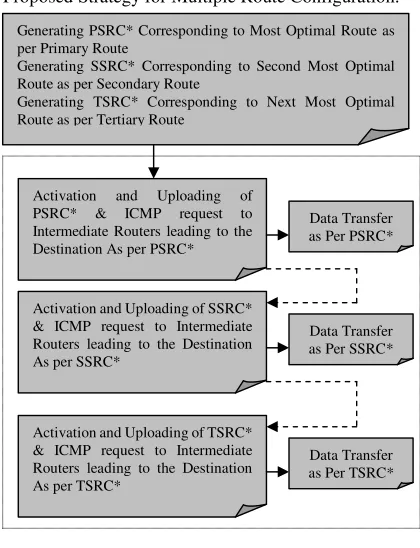
C 192.168.33.0 is directly connected, Ethernet0/1 Proposed Strategy for Multiple Route Configuration:
PSRC: Primary Static Route Configuration. SSRC: Secondary Static Configuration. TSRC: Tertiary Static Route Configuration.
Failure / Success of ICMP request respectively. For Primary Route, if number of Static Routes Configured at Source & Destination is n; then number of Static Routes needed to be configured at Source & Destination for Secondary and Tertiary Route is n + 1 & n + 2 respectively. In addition to Static Route Configuration at Intermediate Routers the number of Static Routes needed to be configured at Source and Destination = 3n + 3. Number of Static Routes needed to be configured at Intermediate Routers depends upon their frequency of falling on Primary, Secondary or Tertiary Routes. For Instance Routers C & J are encountered on both Secondary & Tertiary Routes and hence require additional 2 Secondary Static Routes while Routers D,A,E,N & O are encountered once and require only 1 Static Route Configuration.
3* B A
2* D E C
1*
F G J
I
H N
L
K O
M
[image:5.612.311.521.66.340.2]
Link Failure @ 1* or 2* or 3* Fig. 7 Activation of SSRC in case of
Primary Route/Link Failure
Generating PSRC* Corresponding to Most Optimal Route as per Primary Route
Generating SSRC* Corresponding to Second Most Optimal Route as per Secondary Route
Generating TSRC* Corresponding to Next Most Optimal Route as per Tertiary Route
Activation and Uploading of PSRC* & ICMP request to Intermediate Routers leading to the Destination As per PSRC*
Data Transfer as Per PSRC*
Activation and Uploading of SSRC* & ICMP request to Intermediate Routers leading to the Destination As per SSRC*
Activation and Uploading of TSRC* & ICMP request to Intermediate Routers leading to the Destination As per TSRC*
Data Transfer as Per SSRC*
With ref to Fig. 7, Failure of Primary Route/Link and Activation of SSRC during communication from H→B, Router Table contents for H after Activation:
Protocol Address Hardware Addr Interface Internet 192.168.33.2 000C.5000.3333 Ethernet0/0 Internet 192.168.34.1 000C.8416.5856 Ethernet0/1 Internet 192.168.35.1 000C.8659.5322 Ethernet0/2 Internet 192.168.25.2 000C.1801.2897 Ethernet0/3 With ref to Fig. 7, Failure of Primary Route/Link and Activation of SSRC during communication from B→H, Router Table contents for B after Activation:
Protocol Address Hardware Addr Interface Internet 192.168.19.2 000C.4809.8723 Ethernet0/0 Internet 192.168.22.1 000C.7040.3851 Ethernet0/1 3* B
A
2* D E C 5*
1*
F G J
4* I
H N
L
K O M
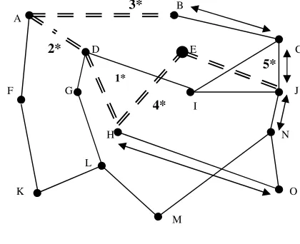
[image:6.612.72.282.227.398.2]Link Failure @ 1* or 2* or 3* or 4* or 5* Fig. 8 Activation of TSRC in case of
Secondary Route/Link Failure
With ref to Fig. 8, Failure of Secondary Route/Link and Activation of TSRC during communication from H→B, Router Table contents for H after Activation:
Protocol Address Hardware Addr Interface Internet 192.168.33.2 000C.5000.3333 Ethernet0/0 Internet 192.168.34.1 000C.8416.5856 Ethernet0/1 Internet 192.168.35.1 000C.8659.5322 Ethernet0/2 Internet 192.168.25.2 000C.1801.2897 Ethernet0/3
With ref to Fig. 8, Failure of Secondary Route/Link and Activation of TSRC during communication from B→H, Router Table contents for B after Activation:
Protocol Address Hardware Addr Interface Internet 192.168.19.2 000C.4809.8723 Ethernet0/0 Internet 192.168.22.1 000C.7040.3851 Ethernet0/1
IX. CONCLUSION
The Static Routing strategy founded on concept of optimality principle based PSRC, SSRC & TSRC may overcome inherent drawback of Backup and Floating Static Routes. If there's anything other than point-to-point copper or fibre connecting two interfaces, there's a good chance that the link between them can fail to pass data even though the interfaces at both ends are marked "up." Such failures are not avoided by floating static routes, though they are avoided by IGPs or BGP [4].If we are using ‘ip mroute’ for configuring multiple static routes we can only configure one ‘ip mroute’ for each prefix, but not two or more as shown above for the ‘ip route
command’[8] in proposed Multiple Static Route Configuration Scheme. Limitations mainly involve maintaining multiple static route configurations which may cost expensive router memory and added cost of processing logic for selecting and uploading second best static route in event of Primary Route. PSRC, SSRC & TSRC based Static routes can be redistributed into dynamic routing protocols but routes generated by dynamic routing protocols cannot be redistributed into the static routing table. Moreover above generated Static Route configuration scheme is more courteous to Static Load Balancing.
REFERENCES
[1] L. Peterson, B. S. Davie,” Computer Networks: A Systems Approach”, Morgan Kaufmann Publishers, 2nd Sub edition, Morgan Kaufmann Series in Networking, Hardcover, 2007, pp. 280-301.
[2] Sean Convery, “Network Security Architectures”, Networking Technology, Cisco Press; 2nd New Ed edition, Hardcover, 2004, pp.262 –
264.
[3] Emad Aboelela,”Network Simulation Experiments Manual”, The Morgan Kaufmann Series in Networking, Paperback, 2007, pp.49-54. [4] Diane Teare, Catherine Paquet, “Building Scalable Cisco Internetwork” Cisco Press, Paperback, 1st edition, Paperback, 2003, pp.557-585. [5] Terry Slattery, Bill Burton, “Advanced IP Routing in Cisco Networks”, Mcgraw-Hill (Tx), 1st edition, 1998, pp.73-86.
[6] K.D. Boese, A B. Kahng, B A. McCoy, G Robins,”Near-Optimal Critical Sink Routing Tree Constructions”, IEEE Transl. On Computer-aided Design of Integrated Circuits and Systems, vol. 14, No. 12, December 1995 1417-1436
[7] A. Srikitja and D. Tipper, "QoS-Based Virtual Private Network Design for an MPLS Network,'' Proceedings of IEEE Globecom 2002, Nov., 2002, Taipei, Taiwan
[8] Configuring multiple Static Mroutes for IPv4 in Cisco IOS.