Abstract— Dimensional and form deviations that arise in CNC turned components due to cutting forces and thermal effects have been traditionally compensated by on-line corrections even when they were not strictly necessary. Machine-tools equipped with multiple sensors must be utilized in order to carry out these compensations what in turn leads to an increment in production costs, the occurrence of undesirable effects such as chatter as well as moving away from optimal conditions. A new approach is proposed in this work for prediction and compensation of deviations in turning by taking them into account at the planning stages prior to machining operations. The proposed model determines the admissible value of deviations in accordance to tolerance limits within the workpiece and utilizes them for setting up the appropriate operation conditions. Initial experimental steps for validating these deviation models are also described.
Index Terms— CAPP, Machining error, Tolerance, Turning.
I. INTRODUCTION
The action of cutting forces in turning results in a deflection of the machine-workpiece-tool system and, in turn, in a difference between the real and the theoretical workpiece diameters.
Most of researchers focused on the prediction and compensation of workpiece dimensional deviations by means of different techniques. In this way, some of them [1] implemented functions to modify the programmed depth of cut in the machine-tool numerical control. Others [2], [3] made predictions of part deflection based on FEM analysis. Only in a few cases the stiffness influence of the whole machine-part-tool system was considered [4]–[7]. Ignoring the effect of cutting forces, some authors [8]–[10] proposed models for compensation of deviations due to the machine-tool thermal drift.
Although numerous contributions have been made for error prediction and compensation, none of them analyzes whether error compensation enables to meet workpiece tolerances or even if it results really necessary to do any compensation when tolerances are not specified.
Manuscript received March 18, 2008. The work described in this communication is part of a research project supported by the Spanish Education and Science Ministry (DPI2007-60437) and FEDER.
G. Valiño is a Senior Lecturer (e-mail: [email protected]). D. Blanco is a Lecturer (e-mail: [email protected]).
B. J. Álvarez is a Researcher in the aforementioned project (e-mail: [email protected]).
S. Mateos is a Senior Lecturer (e-mail: [email protected])
The corresponding address for all authors is: Department of Manufacturing Engineering, University of Oviedo, Campus de Gijón, 33203 Gijon, SPAIN.
θ(a) z
x δΤ(a)
a
θ(a) x
z a
δΤ(a)
z a δΤ(a)
x
θ(a)
(a) Turning
θ(a) x
z a
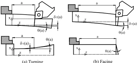
[image:1.595.309.548.189.299.2](b) Facing Fig. 1. Form errors in turning and facing due to deflections. A new approach is proposed in this work for prediction of deviations in turning and their compensation at the planning stages only when really necessary, according to tolerances. Quantitative relationships between the different types of machining errors and the different types of tolerances are determined and proposed as constraints for setting up the optimal cutting conditions prior to machining. The models were developed for workpieces with both external and internal features and variable section along its axis of rotation. Main clamping methods in turning (on a chuck, between-centre and chuck-tailstock) were also considered.
II. RADIAL DEVIATIONS IN TURNED PARTS A. Characterization of form errors in turning
Once finished machining operations, the deflection due to cutting forces disappears and the elastic recovery of material causes the workpiece axis to return to its original position, but this entails a defect of form in the workpiece surfaces equivalent to the deflection that the axis had undergone. In this sense, turning of cylindrical or conical surfaces leads, in fact, to surfaces with a third-order polynomial profile [4] (Fig. 1a). Similarly, facing of front surfaces leads to conical surfaces with a lack of perpendicularity with regard to the symmetry axis (Fig. 1b). The conicity of real front faces is directly related to the turn θ (z) of the section and to the total elastic deflection δT (z). For the section in which the cutting
tool is applied (z = a) this relation will be: ( )
tan ( ) T
z a
d z
a
dz δ θ
=
⎛ ⎞
= ⎜ ⎟
⎝ ⎠ (1)
B. Characterization of radial deviations
The total deviation in the radial direction δT (z) of a turned
Machining Error Predictive Model in a CAPP
system for turning: Formulation and Initial Tests
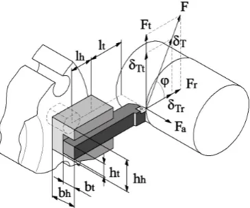
Fig. 2. Cutting force and deflection components.
component at a distance z from the chuck is composed by simultaneous factors related to deformations caused by cutting forces, such as the spindle-chuck system δsc (z), the
toolpost δtp (z), the workpiece deflection δp (z) and the
thermal effectsδth (z) [5], [11]. This can be expressed as:
( ) ( ) ( ) ( ) ( )
T z sc z tp z p z th z
δ =δ +δ +δ +δ (2)
Deviations can be obtained for the tangencial (Z) and radial (X) directions (Fig. 2).
The contribution of the spindle-chuck system can be expressed for these directions [5] as:
2
2 3 3 2
2
1 2 2
- 2 ( ) -2 -2 a
r r r
sc r
r r r r
a
r r
r r r
F
F F D D F
z z z
k k k k
F D Lc
F F Lc
k k k
δ =⎛⎜ + ⎞⎟ + ⎛⎜ ⎞⎟
⎝ ⎠ ⎝ ⎠ ⎛ ⎞ +⎜ + ⎟ ⋅ ⎝ ⎠ (3) 2
2 3 3 2
2
1 2 2
- 2
( )
-2
-2
t t a t
sct
t t t t
t a t
t t t
F F F D D F
z z z
k k k k
F F D Lc F Lc
k k k
δ =⎛⎜ + ⎞⎟ + ⎛⎜ ⎞⎟
⎝ ⎠ ⎝ ⎠
⎛ ⎞
+⎜ + ⎟
⎝ ⎠
(4)
In these expressions, sub-indices r and t refer to radial and tangential directions respectively; Fr, Ft and Fa are the cutting
force components in the radial, tangential and feed directions (Fig. 2); D is the machining diameter; k1, k2 and k3 are the stiffness constants for the spring-model of the system [5], [6]. The contribution of the toolpost is mainly due to a shortening of the tool and the tool-holder in the radial direction. Therefore, it can be expressed as:
( ) t h
tp r
t t h h
l l
z F
A E A E
δ = − ⋅⎛⎜ + ⎞⎟
⋅ ⋅
⎝ ⎠ (5)
where Fris the radial component of the cutting force, lt, At
and Et the cantilever length, cross section and elastic
modulus for the tool respectively, and lh, Ahand Ehthe length,
cross section and elastic modulus for the tool-holder (Fig. 2). Based on strain-energy, the contribution of the workpiece deflection for the chuck clamping method when a cutting force is at z = a (distance between force and chuck) will be:
(
)
21 4 4 int 1 2 2 int 4 ( ) 1 Zi Zi
i ext i p
Zi i
Zi
i ext i
a z F
dz
E r r
a
F dz
G r r
π δ χ π + + ⎛ − ⎞ ⎜ ⋅ ⋅ ⎟ − ⎜ ⎟ = ⎜ ⎟ ⎜ + ⋅ ⋅ ⎟ ⎜ − ⎟ ⎝ ⎠
∫
∑
∫
(6)where i represents each zone with constant cross section, E is the elastic modulus, G the shear modulus, I the moment of inertia and χis the shear factor.
For the between-centre clamping method, the expression is:
(
)
(
)
2 2
1
2 4 4
int 2
1
2 2 2
int 4 ( ) 1 i i i i Z p Z
i i ext i
Z
Z
i i ext i
F L a z
a dz
L E r r
F L a
dz
L G r r
δ π χ π + + ⎛ ⎞ − = ⎜⎜ ⎟⎟ − ⎝ ⎠ ⎛ ⎞ − + ⎜⎜ ⎟⎟ − ⎝ ⎠
∑ ∫
∑ ∫
(7)And in the case of the chuck-tailstock clamping method, the expression becomes:
(
)
(
)
(
)
(
(
)
)
(
)
2
2 2 2
6 0 2 2 2 6 0 3 ( ) 4
2 2 2
4
a p
a
F L a L L a
a dz
L A G
F L a L a a L z L a a L
dz L E I
χ
δ = ⋅ − ⎡⎣ − − ⎤⎦
⎡ ⎤ − ⎣ − − + ⋅ ⋅ − ⎦ +
∫
∫
(8) Finally, the contribution of the thermal drift takes placemainly in the radial direction and depends on factors such as spindle speed, feed rate, machine-tool operation time and ambient temperature. Some authors use these parameters as input data to a neural network, which output is the radial thermal drift [10], [11].
III. EXPERIMENTAL STIFFNESS CHARACTERIZATION OF THE SPINDLE-CHUCK SYSTEM
The stiffness characterization of the spindle-chuck system is based on determining the stiffness constants k1, k2 and k3 for the spring-model of the system along tjhe tangential and radial directions [5]. Since the stiffness of the spindle-chuck system is independent of both the part geometry and the thermal variations, the value of these constants will be the same while the system remains invariable.
Deviations of the spindle-chuck system must be isolated from the rest of deviations for the experimental determination of the stiffness constants. For this, a cylindrical part with superior order stiffness is machined, so that the influence of the other components can be neglected.
coolant was used to avoid the effect of temperature in the cutting zone. After measuring the workpiece in a CMM, radial deviations were obtained at different positions along its length and were fitted by means of a third-order polynomial (fitting coefficient R2 = 0.99) according to expressions
(2)–(6) for the total deviation δT (z). The contribution of the
toolpost shortening and the workpiece deflection was also analyzed and it was concluded that any of them were significant with respect to the total deviation and, consequently, most part of error was due to the lack of stiffness of the spindle-chuck system, whose expressions (3) and (4) are second-order polynomials of type P(z) = A·z2 + B·z + C:
Therefore, the total deviations previously obtained in the CMM can be now fitted by a second-order polynomial and its coefficients determined from that experimental results. After decomposition of this new polynomial along the radial (X) and tangential (Z) directions, the stiffness constants are determined by equalizing the experimental coefficients with those in (3) and (4).
As results of the test, the coefficients of the fitted polynomial were: A = 5.733 × 10⁻⁷, B = 1.226 × 10⁻⁴ and C = 92.834. And the value of the stiffness constants: k1r= -1.6 × 10⁵, k2r= 1.28 × 10⁹, k3r= -1.52 × 10¹⁰ and
k1t= -1.026 × 10⁵, k2t= 1.564 × 10⁹, k3t= 1.317 × 10¹⁰.
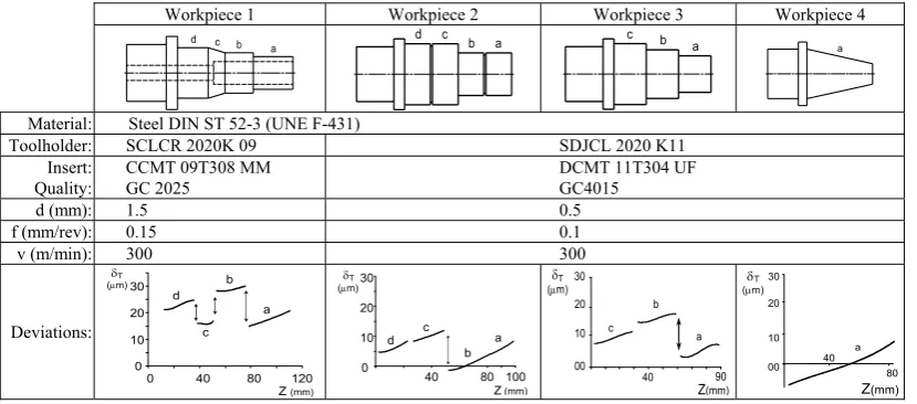
IV. TESTS FOR THE WORKPIECE DEFORMATION MODEL Machining tests were carried out to check the validity of the predictive deviations model. Several workpieces of varied geometry (Fig. 3) were machined following a profiling strategy on different zones (a, b, c and d). Deviation graphs represented after measuring the workpieces within a CMM show discontinuities between 10 and 20 μm located in certain zones where the cross section changes. On the other hand, dimensional deviation increases as the distance to the chuck does. Moreover, this tendency is greater as external zones have smaller diameter and lower stiffness.
The analysis of these results led to guess that discontinuities had no relation with the workpiece geometry but with a positioning error of the tool-carriage. A verification of the lathe confirmed that hypothesis. This is a
type of systematic error which can be precisely measured in the graphs for a uniform and increasing function. After applying these corrections for the testing workpieces, the deviation graphs could be fitted by a third-order polynomial with an adequate precision of R2 = 0.995. Nevertheless, some inconveniences appeared in the experimentation mainly due to a lack of precision in calibration of tools and in workpiece measurement at the lathe. The only reliable measurements were obtained within a CMM but they were absolute measurements that did not allow for determining the contribution of each individual component, especially the thermal drift.
V. RELATIONSHIP BETWEEN DEVIATIONS AND TOLERANCES Although dimensional and geometrical specifications of a part are expressed on drawings by means of dimensional and geometrical tolerances, no relationships were found in literature between form deviations derived from machining process and value of tolerances. Nevertheless, it is essential to know these relationships for setting up the appropriate machining conditions. Therefore, in the next sections each type of tolerance will be analyzed according to ISO standard and geometrically related to the feasible deviation types in turned parts.
A. Length tolerance
Due to the form error, the real distance between two front faces depends on the zone in which the measurement is taken. Actual measurements will be between the values '
min L and '
max
L (Fig. 4a) and they will be admissible when the following expression is satisfied:
'
max n u
L ≤L +dL and '
min n l
L ≥L +dL (9)
where Ln is the nominal distance and dLu and dLl are the
upper and lower limits of longitudinal tolerance, respectively. Considering distances ei and ej in Fig. 4a, the
following relation can be established:
' '
max- min i j
L L = +e e (10)
Workpiece 1 Workpiece 2 Workpiece 3 Workpiece 4
a b c
d d c b a
a b c
a
Material: Steel DIN ST 52-3 (UNE F-431)
Toolholder: SCLCR 2020K 09 SDJCL 2020 K11 Insert:
Quality:
CCMT 09T308 MM GC 2025
DCMT 11T304 UF GC4015
d (mm): 1.5 0.5
f (mm/rev): 0.15 0.1
v (m/min): 300 300
Deviations: 0 10 20 30
0 40 80 120 a b
c d
Z (mm) (μδm)T
0 10 20 30
40 80
(μm)
a d c
b 100
δT
Z(mm) 00 10 20 30
40 90
a b
c
Z(mm) (μδm)T
00 10
40 80 20
30
Z(mm)
[image:3.595.93.508.592.775.2]a (μδm)T
Taking into account (9) and (10) and that the tolerance zone t is the difference between the upper and lower limits, the following is the condition for the measurement to meet the tolerance:
-i j u l
e +e ≤dL dL =t (11)
where distances ei and ej can be expressed in terms of the turn
of sections θ i and θ j:
-tan 2
M i mi
i i
D D
e = ⋅ θ and - tan
2
Mj m j
j j
D D
e = ⋅ θ (12)
B. Diametrical tolerance
Due to the form error of the cylindrical surfaces, the diameter of the workpiece depends on the location of the measurement
point, varying between a maximum and a minimum value ( '
Md
D and '
md
D ) (Fig. 4b). The measurement is admissible when the following expression is satisfied:
'
Md n u
D ≤D +dD and '
md n l
D ≥D +dD (13)
where Dn is the nominal diameter and dDu and dDl are the
upper and lower limits of the diametrical tolerance, respectively.
Once the machining of the cylindrical surface is finished, the maximum error is given by the difference between the maximum δ T Md and the minimum δ T md deflections. The
following relation can be deduced from geometry (Fig. 4b):
' - ' 2
-Md md T Md T md
D D = δ δ (14)
Tolerance representation Tolerance interpretation Accepting condition
(a) Length
+dLl
+dLu Ln
+dLl
+dLu
Ln L'min
L'max
ei ej
θi
θj
DMi Dm i Dmj DMj
L'min
L'max
ei ej
θi
θj
DMi Dm i Dmj DMj
i j u l
e +e ≤dL - dL = t
(b) Diametrical
Dn+dDu
+dDl Dn+dDu
+dDl
D'md δΤmd
D'Md δΤΜd
D'md δΤmd
D'Md δΤΜd
u l T Md T md
dD dD t
δ -δ =
2 2
− ≤
(c) Flatness
tt
t
ei
θi
t
ei
θi
i e ≤t
(d) Cylindricity
tt
D'md
δΤmd t
D'Md
δΤ Μd
D'md
δΤmd t
D'Md
δΤ Μd
T Md T md
δ -δ ≤t
(e)
Profile α
Dn md Dn Md
t
α
Dn md Dn Md
t
D'md
δΤmd
α D'Md
α t
δΤ Μd
D'md
δΤmd
α D'Md
α t
δΤ Μd
T Md T md t
δ +δ
cosα
≤
(f) Parallelism
tt
θi ej
t
i ei
θj
θi ej
t
i ei
θj
j e ≤t
(g) Perpendicularity
tt
i
ej t
θj
i
ej t
θj
ej t
θj
j e ≤t
(h) Total-radial
Runout
tt
D'md
δΤmd t
D'Md
δΤ Μd
D'md
δΤmd t
D'Md
δΤ Μd
T Md T md
δ -δ ≤t
(i) Total-axial
Runout
tt
t
ej
θj
i t
ej
θj
i
[image:4.595.61.534.273.749.2]j e ≤t
By considering (13) and (14) and that the tolerance zone t is the difference between the upper and lower deviations, the following is the condition to meet the tolerance:
2δT Md-δT md ≤dD dDu- l =t (15)
C. Geometrical tolerance of flatness
Definition of each type of geometrical tolerance has been considered based on ISO standard (ISO 1101:1983). According to that, the flatness tolerance establishes a zone of acceptance t with respect to the nominal orientation of the controlled face, within which the real machined surface must stand. In order to satisfy this condition, the form error must be lower than the width of the tolerance zone (Fig. 4c). Considering this and being distance ei calculated as in (12),
the condition will be:
i
e ≤t (16)
D. Geometrical tolerance of cylindricity
The cylindricity tolerance establishes a volume between two coaxial cylinders whose difference of radii is the value of the tolerance zone t. The machined surface must lie between these two cylinders.
The maximum error obtained when machining the cylindrical surface is given by the difference between the maximum δT Md and minimum δT md deviations. Being DMd'
and '
md
D the maximum and minimum surface diameters, the following relations can be deduced from geometry (Fig. 4d):
' ' 2
Md md
D −D ≤ ⋅t (17)
' ' 2
Md md T Md T md
D −D = ⋅δ −δ (18)
And, considering (17) and (18), it is obtained:
T Md T md t
δ −δ ≤ (19)
E. Geometrical tolerance of profile of a surface
This tolerance specifies a zone between two surrounding spherical surfaces whose diameter difference is the value of the tolerance zone t and whose centres are located onto the theoretical surface. According to norm ISO 3040:1990, for the case of a conical surface, the tolerance zone becomes the space between two cones of the same angle than the datum and equidistant to that cone the half of the tolerance value.
All diameters of the real machined surface must lie within the tolerance zone, including the diameters in which deviation is maximum '
Md
D and minimum '
md
D , which will satisfy:
'
2 2 cos
Md n Md
D D t
α −
≤
⋅ and '
2 2 cos
md n md
D D t
α −
≤
⋅ (20)
where Dn Md and Dn md are respectively the nominal diameters
of the cone measured in the positions of maximum and minimum diametrical deviation (Fig. 4e).
On the other hand, workpiece deflections in the zones of maximum and minimum deviations are denoted as δ T Md and
δ T md, respectively. Their values can be expressed as:
'
2
Md n Md T Md
D D
δ = − and
'
2
md n md T md
D D
δ = − (21)
The final condition is derived from (20) and (21):
cos
T Md T md
t
δ δ
α
+ ≤ (22)
F. Geometrical tolerance of parallelism
Parallelism is applied between front faces in turned parts. Let be i the datum and j the related face. According to tolerance definition, the related surface must lie within an space defined between two planes parallel to the datum and distanced one another the value of the tolerance t (Fig. 4f). Although even the datum has a form error, according to norm ISO 5459:1981, this surface will be considered perpendicular to the part axis and, consequently, also the planes which define the tolerance zone. Considering this, and calculating ej
as in (12), the geometrical condition to meet the tolerance will be:
j
e ≤t (23)
G. Geometrical tolerance of perpendicularity
Perpendicularity is applied between a front face and a feature axis in turned parts. Two different situations must be considered depending on which of both elements is the datum and which the controlled one.
1) Axis as datum, a face is controlled:
The tolerance zone is the space between two planes perpendicular to the datum axis and distanced one another the value of the tolerance t (Fig. 4g). Considering this, and calculating ej as in (12), the geometrical condition will be:
j
e ≤t (24)
2) Face as datum, an axis is controlled:
The tolerance zone is the space within a cylinder of diameter t, and axis perpendicular to the datum face. The elastic recovery of the part axis after machining leads to affirm that any deviation of this element does not depend directly on the cutting action but on other technological aspects such as a bad alignment of the workpiece in the lathe. For this reason, no relation can be properly established between this error and the deviation caused by cutting forces. H. Geometrical tolerance of coaxiality
the possible error is not due to deviations caused by cutting forces but to other causes.
I. Geometrical tolerance of circular runout
For circular-radial runout, the tolerance zone is the area between two concentric circles located into a plane perpendicular to the axis, whose radii difference is the tolerance t and whose centre is located at datum axis. Since form errors derived from cutting forces are completely symmetrical with respect to the workpiece rotation axis, the error evaluated throughout this tolerance does not depend on these forces, but on the workpiece deflection caused by the clamping force or by a lack of workpiece alignment.
A similar situation takes place regarding circular-axial runout.
J. Geometrical tolerance of total runout
The total-radial runout is used to control cumulative variations of circularity and cylindricity of surfaces constructed around a datum axis. As in the case of circular- radial runout, circularity does not depend on deviations from cutting forces but cylindricity does. Therefore, the condition to be satisfied in this case is the same than in (19) (Fig. 4h).
The total-axial runout controls cumulative variations of perpendicularity and flatness of front faces at a right angle to the datum axis. Therefore, the relation of this error with deviations coincides with expressions obtained for flatness and perpendicularity in (16) and (24) respectively (Fig. 4i).
VI. MAXIMUM DEVIATION AS OPTIMIZATION CONSTRAINT The optimization of cutting conditions in turning is the final stage of process planning in which not only mathematical considerations about the objective function have to be done (e.g., time, cost or benefit) but also there are several constraints that restrict the best solution.
Common constraints are related to ranges of cutting parameters (cutting speed, feed-rate and depth of cut), ranges of tool-life and other operating limits such as surface finish, maximum power consumption and maximum force allowed. The cutting force constraint is imposed to limit the deflection of the workpiece or cutting tool, which result in dimensional error, and to prevent chatter [12]. Traditionally, the value of this constraint has not been clearly determined. Nevertheless, the relationships between workpiece deviations and tolerances described in the previous sections can also be considered as relationships between cutting forces and maximum deviations allowed and, therefore, all together can be used as optimization constraints.
VII. CONCLUSION
This work provides a mathematical model based on strain energies for prediction of deviations in the turning process of workpieces with complex external and/or internal geometry and which takes into account the main clamping procedures in turning. The experimental tests carried out for validating these models were successful for stiffness characterization of the spindle-chuck system. On the other hand, the tests for analysing the workpiece deviation under the cutting forces
led to qualitative results near the model predictions, although it was not possible to confirm the quantitative results yet, due to a lack of precision in calibration of tools and in workpiece measurement in the lathe.
Likewise, an analysis of maximum deviations is developed according to each tolerance specification and an accepting criterion is proposed in each case so that compensation of the calculated errors must be carried out only when tolerances are not met. This becomes a different approach with regard to other works developed up to date which propose to make error compensations in all cases, even when they are not necessary according to tolerances. Moreover, the results of this analysis are utilized by a turning CAPP system as constraints for the optimization of cutting conditions and it also can be useful for deciding the most suitable clamping method for setting up the workpiece on the lathe.
REFERENCES
[1] S. Yang, J. Yuan and J. Ni, “Real-time cutting force induced error compensation on a turning center,” Int. J. of Machine Tools & Manuf.,
vol. 37(11), 1997, pp. 1597-1610
[2] A.-V. Phan, L. Baron, J.R. Mayer and G. Cloutier, “Finite element and experimental studies of diametrical errors in cantilever bar turning,”
App. Math. Modelling, vol. 27(3), 2003, pp. 221-232.
[3] Liu Zhan Qiang, “Finite difference calculations of the deformations of multi-diameter workpieces during turning,” J. of Mat. Processing Technology, vol. 98(3), 2000, pp. 310-316.
[4] L. Carrino, G. Giorleo, W. Polini and U. Prisco, “Dimensional errors in longitudinal turning based on the unified generalized mechanics of cutting approach. Part II: Machining process analysis and dimensional error estimate,” Int. J. of Machine Tools and Manuf., vol. 42(14), 2002, pp. 1517-1525.
[5] G. Valiño, S. Mateos, B.J. Álvarez and D. Blanco, “Relationship between deflections caused by cutting forces and tolerances in turned parts,” Proc.of the 1st Manuf. Eng. S. Int. Conf. (MESIC), Spain, 2005.
[6] D. Mladenov, “Assessment and compensation of errors in CNC turning,” PhD Thesis, UMIST, UK, 2002.
[7] S. Hinduja, D. Mladenov and M. Burdekin, “Assessment of force-induced errors in CNC turning,” Annals of the CIRP, 52(1), 2003, pp. 329-332.
[8] J. Yang, J. Yuan and J. Ni, “Thermal error mode analysis and robust modelling for error compensation on a CNC turning center,” Int. J. of Machine Tools and Manuf., vol. 39(9), 1999, pp. 1367-1381. [9] V.A. Ostafiev and A. Djordjevich, “Machining precision augmented by
sensors,” Int. J. of Prod. Res., vol. 37(1), 1999, pp. 91-98.
[10] X. Li, P.K.Venuvinod, A.Djorjevich and Z. Liu, “Predicting machining errors in turning using hybrid learning,” Int. J. of Adv. Manuf. Tech., vol. 18, 2001, pp. 863-872.
[11] X. Li and R. Du, “Analysis and compensation of workpiece errors in turning,” Int. J. of Prod. Res., vol. 40(7), 2002, pp. 1647-1667. [12] Y. C. Shin and Y. S. Joo, “Optimization of machining conditions with