Abstract— Most outdoor applications such as surveillance, terrain classification and autonomous navigation require robust detection of image features. Under bad weather conditions, however, the contrast and colors of images are degraded and it is imperative to include mechanisms that overcome weather effects from images in order to make vision systems more reliable. Unfortunately it turns out that effects of weather cannot be overcome by simple image processing techniques. There are some existing methods to enhance contrast restoration in bad weather. Some of the methods provide contrast restoration but do not provide considerable visibility enhancement while other methods provide more visibility but do not maintain the color fidelity. A novel method is proposed in this paper that not only enhances visibility but also maintains the color fidelity. This method consists of three phases. The first two phases consists of estimating a measure of degradation and its removal while the final phase uses a novel wavelet fusion method to obtain the enhanced image. Performance analysis is carried out with the help of a contrast improvement index and sharpness measure. The experimental results on real images show the effectiveness of the approach.
Keywords— Aerosol, airlight, color fidelity, contrast correction, color model.
I. INTRODUCTION
NE of the major reasons for accidents in air, on sea and on the road is the poor visibility due to presence of fog or mist in the atmosphere. During winter, visibility is worse, sometimes up to few feet only. Under such conditions, light reaching the human eye is extremely scattered by constituents of atmosphere like fog, haze and aerosols and the image is severely degraded.
Images taken under such bad weather conditions suffer from degradation and severe contrast loss. The loss of image quality is a nuisance in many imaging applications. For example, in underwater imaging in murky water, the detection of artifacts becomes difficult due to poor image quality. Hence, imaging must be performed at close range and this usually results in a long time required to inspect a small area. Another example is in the navigation of surface ships and aircraft in bad weather. In weather conditions such
Prof. Dr. M. Wilscy is with Department of Computer Science, University of Kerala, Karyavattom – 695581, Trivandrum, Kerala, India (e-mail: [email protected], Phone : +91 471 2416360).
Jisha John, Mtech, Department of Computer Science, University of Kerala, Karyavattom – 695581, Trivandrum, Kerala, India (e-mail: [email protected], Phone : +91 9495556378).
as fog, visibility is low and navigation is more difficult, dangerous and slow.
The image in outdoor scene is degraded by optical scattering of light which produces additional lightness present in some parts of the image, an effect that has been referred to as “atmospheric background radiation” [1], [2] or “airlight” [3], [4]. This results in degradation of image contrast, as well as alteration of scene color, which finally leads to a poor visual perception of the image.
Contrast enhancement methods fall into two groups: non-model-based and model-based. Non-model-based methods analyze and process the image Non-model-based solely on the information from the image. The most commonly used non-model-based methods are histogram equalization and its variations [15]–[18].
For color images, histogram equalization can be applied to R, G, B color channels separately but this leads to undesirable change in hue. Better results are obtained by first converting the image to the Hue, Saturation, Intensity color space and then applying histogram equalization to the intensity component only [14]. However, even this method does not fully maintain color fidelity.
There are also other non-model-based methods like unsharp masking [8], approaches based on the Retinex theory [9]–[11], and wavelet-based methods [12],[13]. Generally, all non-model-based methods have a problem with maintaining color fidelity. They also distort clear images, which is an important limitation for fully automatic operation.
Model-based methods use physical models to predict the pattern of image degradation and then restore image contrast with appropriate compensations. They provide better image rendition but usually require extra information about the imaging system or the imaging environment.
In [5] John P Oakley and Hong Bu have suggested a method of enhancement by correcting contrast loss by maintaining the color fidelity. In this method it is assumed that if the distance between a camera position and all points of a scene represented by an image generated by the camera is approximately constant, the airlight will be uniform within the image. But in most real-time situations this assumption is not valid. This method gives good contrast restoration but does not provide much visibility enhancement.
To enhance the visibility Robby.T.Tan et.al [6] have proposed a visibility enhancement method which makes use of color and intensity information. Visibility is greatly improved in the resulting images but color fidelity is
A Novel Wavelet Fusion Method for Contrast Correction and
Visibility Enhancement of Color Images
M.Wilscy and Jisha John
not maintained. Hence in situations were the naturality of the image is important this method cannot be used.
In this work a method for enhancing visibility and maintaining color fidelity is proposed using wavelet fusion. This method mainly consists of 3 phases. Given an input image, first phase is to apply a contrast correction using the depth information. Here we compute the value of airlight present in the image by optimizing a cost function. The second phase consists of finding an approximate airlight value by using the intensity information of YIQ color model. Contrast restoration in the first and second phase is performed by removing the airlight from the image and applying depth information. The third and final phase of the proposed method consists of a wavelet fusion method to get a resultant image which has considerable visibility improvement and also maintains the color fidelity.
The rest of the paper is organized as follows: In Section II we will discuss the atmospheric scattering models concentrating on the airlight model which forms the basis of this method. In section III, the contrast correction method is given which forms the first phase of this work. In section IV the approximate airlight estimation method is discussed. Section V introduces the wavelet fusion method. To show the effectiveness of the proposed method, performance analysis is done in section VI with the help of a contrast improvement index and sharpness measure. Section VII includes the experimental results and discussion.
II. ATMOSPHERIC SCATTERING MODELS
Scattering of light by physical media has been one of the main topics of research in the atmospheric optics and astronomy communities. In general, the exact nature of scattering is highly complex and depends on the types, orientations, sizes, and distributions of particles constituting the media, as well as wavelengths, polarization states, and directions of the incident light [1], [2]. Here, we focus on one of the models: airlight, which form the basis of our work.
A. Airlight
While observing an extensive landscape, we quickly notice that the scene points appear progressively lighter as our attention shifts from the foreground toward the horizon. This phenomenon, known as airlight results from the scattering of environmental light toward the observer, by the atmospheric particles within the observer’s cone of vision.
The environmental illumination can have several sources, including direct sunlight, diffuse skylight and light reflected by the ground. While attenuation causes scene radiance to decrease with path length, airlight increases with path length. It therefore causes the apparent brightness of a scene point to increase with depth. The, the irradiance due to airlight is given by
E(x) =I∞ρ(x)e-βd(x) + I∞(1-e-βd(x) ). (1)
The first term in the equation represents the direct transmission, while the second term represents the airlight. E is the image intensity, x is the spatial location, I∞
is the atmospheric environmental light, which is assumed to be globally constant and ρ is the normalized radiance of a scene point, which is the function of the scene point reflectance, normalized sky illumination spectrum, and the spectral response of the camera. β is the atmospheric attenuation coefficient. d is the distance between the object and the observer.
It is the second term in (1) or airlight that causes degradation in the image taken under bad weather conditions and hence all contrast restoration methods are aimed at removing this additional lightness from the image
III. CONTRAST CORRECTION
In Simple Contrast Loss, the degradation can be described by the applying
y
= m (x –
λ
)
(2) to each pixel of the image, where‘x’ is the distorted pixel value
‘λ ’ is an estimate of the airlight-contributed part of the pixel value
‘m’ is a scaling parameter
and ‘y’ is a modified pixel value.
To estimate the airlight in an image the normalized brightness value needs to be known.
A. Normalized brightness and airlight
The normalized brightness, BK , is defined by:
Bk = k k
ρ
ρ
, k=1, 2,…….K (3)
where k is the pixel position, ρk is the value of the image at pixel position k, and
ρ
k is the output of a spatial low-pass filter at pixel position k. K is the total number of pixels in the image. The type of spatial low-pass filter is not critical. The Gaussian-shaped kernel is used here but other shapes provide similar results. The Gaussian shape is preferred since it introduces the least spurious structure. Also, an efficient recursive implementation of the Gaussian kernel may be used to reduce computational effort. For natural images, Bk has a near-symmetric and near-Gaussian distribution with a mean close to unity.B. Correcting Contrast
In order to perform contrast correction, an airlight estimate is required. An algorithm is used for estimating the level of this airlight given the assumption that it is constant throughout the image. Airlight estimation is done by finding the minimum value of a cost function (4) that is a scaled version of the standard deviation of the normalized brightness is given by;
{
p k K}
GM K k
p p STD
S k
k k
gm( ) ' : 1,2,.... . : 1,2,.... '
= − ⎭ ⎬ ⎫ ⎩
⎨ ⎧
= − −
= λ
λ λ
Where
GM
{}
.
denotes the geometric mean. The geometric mean can also be written as{
}
⎭ ⎬ ⎫ ⎩ ⎨ ⎧ = =∑
= K k k k x k K k x GM 1 ) ln( 1 exp ... 2 , 1:
(5)
Another possible variation on the cost function is to use sample variance in (4) rather than sample standard deviation, in which case the scaling factor must be squared.
⎭ ⎬ ⎫ ⎩ ⎨ ⎧ − ⎟⎟ ⎠ ⎞ ⎜⎜ ⎝ ⎛ − − =
∑
∑
= = K k k K k k k k k k S 1 2 2 1 ) ln( 1 exp . 1 )( ρ λ
λ ρ
ρ ρ
λ (6)
Obtain the optimum value of λ which minimizes the cost function by calculating,
{
( )}
min arg
ˆ Sgm
λ
c = (7)
This is done using a standard optimization algorithm. This estimated value of λ represents the airlight present in the image. From this computation we can rewrite (1) as
E(x)=I∞ρ(x)e-βd(x) + λ (8)
Hence the enhanced image
I∞ρ(x) = (E(x) - λ) eβd(x) (9)
From (1) we can again write
λ
=I
∞(1-e
-βd(x))
(10)So, in order to estimate eβd(x) we can rewrite (10) as
λ
=
(
I
∞r+
I
∞g+
I
∞r)(
1
−
e
−βd(x))
,
Hence) ( 1 1 ) ( r g r x d I I I e ∞ ∞ ∞+ + − = λ
β
(11)
were
(
I
∞r+
I
∞g+
I
∞r)
, namely, the environmental light, is assumed to be the largest intensity in the image. λ is found by optimizing the cost function (4) and depth information is obtained from (11). Thus (9) gives the contrast corrected image. Section IV and V describes how visibility enhancement can be achieved.IV. INTENSITY BASED ENHANCMENT To accomplish the goal of intensity enhancement, airlight (λ) is computed based on the intensity value of YIQ color model [6] which is defined as
b g
r
E
E
E
Y
=
0
.
257
∗
+
0
.
504
∗
+
0
.
098
∗
(12)were
E
r,E
g,E
brepresents the r, g and b color channels respectively.It is assumed that the value of Y is the value of λ. However the values of λ are approximated values and thus to create a better approximation, these values are diffused by using Gaussian blur. Depth information,eβd(x) is computed as described in the earlier section by (11). Enhanced image is obtained as in (9).This resultant image contains all the detailed information present in the image.
V. WAVELET FUSION
The first phase described in section III results in an image maintaining the color fidelity but the visibility is not enhanced particularly in scenes were the distribution of airlight is not uniform. The second phase uses an approximate airlight estimation method which results in an image with enhanced visibility but the color fidelity is not maintained. In the third phase a novel fusion method is used which helps in extracting the useful information from both images and hence obtaining an image with enhanced visibility at the same time maintaining the color fidelity. The daubechies wavelet is used here.
The two images obtained as described in section III and IV are decomposed by using daubechies wavelet method. The wavelet decomposition is done using wavelet transform. The four images obtained per image after decomposition are coefficients extracted from the given image.
The first image is actually approximate coefficients displayed while the second image is formed when horizontal coefficients are displayed. The third image is formed when vertical coefficients are displayed. And the final image comes when diagonal coefficients are displayed. These coefficients are obtained by the following process.
The image is actually passed through some sets of filters then these images are obtained. The image is passed through two low pass filters one aligned vertically and one aligned horizontally.
If image is passed through two filters, one low pass aligned horizontally and a high pass filter aligned vertically the vertical coefficients are obtained. Vertical coefficients and are obtained from high pass filter aligned horizontally and low pass filter aligned vertically. And the final image is for diagonal coefficients which are obtained with both high pass filters aligned horizontally and vertically.
After obtaining the wavelet bands of the two images merge the coefficients by obtaining the mean value of the approximate coefficients and maximum value from the detailed coefficients. The resultant image is an enhanced image which contains the maximum details and also maintains the color fidelity.
VI. PERFORMANCE ANALYSIS
There is a lack of methodology to assess the performances of the methods or to compare them with one another. Unlike image quality assessment or image restoration areas, there is no easy way to have a reference image, which makes the problem not straightforward to solve.
Original processed
C
C
(13)
were C is the average value of the local contrast measured with a 3*3 window as:
min max
min max
+
− (14)
In order to evaluate the effectiveness of the resultant image a well-known benchmark-image sharpness measure, the tenengrad criterion [19] [20] can be used. The tenengrad criterion is based on gradient
∇
I
(
x
,
y
)
at each pixel (x, y), were the partial derivatives are obtained by a high-pass filter, eg., the sobel operator, with the convolution kernelsi
xand
i
y. The gradient magnitude is given by2
2 ( ( , ))
)) , ( ( ) ,
(x y i I x y i I x y
S = x∗ + y∗ (15)
And the tenengrad criteria is formulated as
TEN=
∑
∑
>
y x
y
x
S
(
,
)
2,
for
S(x,
y
T)
(16)Were T is the threshold. The image quality is usually considered higher if its tenengrad value is larger.
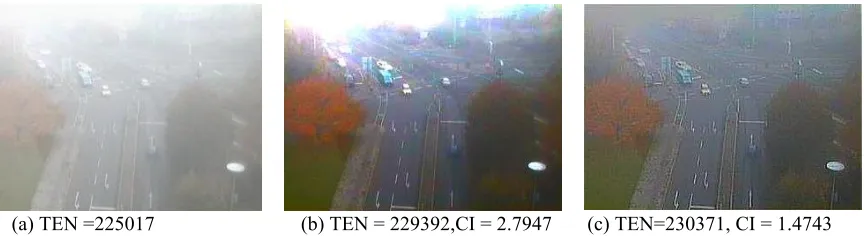
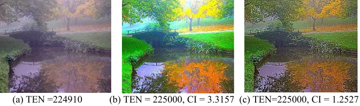
[image:4.612.55.553.145.476.2]The tenengrad values (TEN) of all images given below has been calculated and listed in corresponding figure, captions. It is noted that images processed using the wavelet fusion method described above gives significantly larger tenengrad values, which indicate the effectiveness of this method. This result agrees with the visual evaluation of human eye.
VII. RESULTS AND DISCUSSION
The performance of the proposed method has been evaluated and compared with conventional methods of contrast enhancement using MATLAB software tool. The performance is analyzed using the measures described above.
As a measure of objective similarity between a contrast restored image and the original one, the mean-squared error (MSE) is used.
MSE (img, org) =
(
)
(
)
[
]
M
N
c
j
i
img
c
j
i
org
c N
i M
j
.
.
3
,
,
,
,
3 1 1 1
2
∑∑ ∑
= = =−
were org is the original color image; img is the restored color image of size N.M.
(a) (b) TEN=224626 (c) TEN=225000, CI= 2.6356 (d) TEN= 225000, CI=1.1555
MSE = 2.0401e +004 MSE = 9.4580 e+ 003
Fig. 1. (a) Original Trees image (256×256) (b) Foggy image (c) After applying method of visibility enhancement (d) After applying proposed method
[image:4.612.62.494.513.631.2](a) TEN =224910 (b) TEN = 225000, CI = 3.3157 (c) TEN=225000, CI = 1.2527 Fig. 3. (a) Scenery image (c) After applying method of visibility enhancement (d) After applying proposed method
The color images used in this paper are Trees, Traffic and Scenery images of size 256×256. The original image, the noisy image (degraded image) and restored images using visibility enhancement method and proposed wavelet fusion method along with their corresponding tenengrad, contrast improvement index values and mean-squared error values are shown in figure1. From experimental results, it has been found that the proposed method has good contrast improvement and visibility (measured by the sharpness measure-tenengrad).It also maintains color fidelity which is shown using the low mean-squared error compared to other method.
Figure 2 and 3 gives the foggy Traffic image and the Scenery image degraded by mist along with the contrast restored images using visibility enhancement method and the proposed method. The contrast improvement index is more for visibility enhancement method but the color fidelity is lost, while the proposed method gives good visibility enhancement and also maintains the color fidelity. The method proposed is not restricted to uniform suspension of airlight and hence is applicable for all real-time scenarios.
VIII. CONCLUSION
In this paper the problem of restoring the contrast of atmospherically degraded images is addressed. This method uses the daubechies wavelets transform to decompose the images into various levels and then the frames are reconstructed by coefficient based fusion. It provides excellent color fidelity as well as visibility enhancement and hence is applicable for all real time operations. Future research will be focused on contrast restoration of images degraded by dense fog or mist.
REFERENCES
[1] S. Chandrasekhar, Radiative Transfer. Dover Publications, Inc.,
1960.Raefal c. Gonzalez, Richard E. Woods, “Digital Image
Processing”, 2nd Ed., Pearson Education, 2002, pp. 147-163. [2] Van De Hulst, Light Scattering by Small Particles. John Wiley and
Sons, 1957Alan C. Bovik and Scott T. Acton, “Basic Linear Filtering
with Application to Image Enhancement”, Handbook of Image and
Video Processing, Academic Press, 2006, pp. 71-79.
[3] J. P. Oakley and B. L. Satherley, “Improving image quality in poor visibility conditions using a physical model for contrast degradation,”,
IEEE Trans. Image Process., vol. 7, no. 2, pp. 167–179, Feb. 1998.
[4] S. K. Nayar and S. G. Narasimhan, “Vision in bad weather,” in Proc
IEEE Int. Conf. Computer Vision, 1999, vol. 2, pp. 820–827
[5] John P Oakley and Hong Bu , “Correction of simple contrast loss in color images”, IEEE Transactions on Image Processing, Vol 16, No:2, February 2007.
[6] Robby T. Tan, Niklas Pettersson Lars Petersson, “Visibility Enhancement of roads with foggy or hazy scenes”, Proceedings of the 2007 IEEE Intelligent Vehicles Symposium Istanbul, Turkey, June 13-15, 2007.
[7] Pengxin Zeng, Huiying Dong, Jiannan Chi, Xinhe Xu, School of Information Science and Engineering, Northeastern University. Shenyang, China, Proceedings of the 2004 IEEE International Conference on Robotics and Biomimetics, August 22-26, 2004, Shenyang, China.
[8] A. Polesel, G. Ramponi, and V. J. Mathews, “Image enhancement via adaptive unsharp masking,” IEEE Trans. Image Process., vol. 9, no. 3, pp. 505–510, Mar. 2000.
[9] D. J. Jobson, Z. Rahman, and G. A. Woodell, “Properties and
performance of a center/surround retinex,” IEEE Trans. Image
Process., vol. 6, no. 3, pp. 451–462, Mar. 1997.
[10] “A multi-scale retinex for bridging the gap between color images and the human observation of scenes,” IEEE Trans. Image Process., vol. 6, no. 7, pp. 965–976, Jul. 1997.
[11] Z. Rahman, D. J. Jobson, and G. A. Woodell, “Retinex processing for automatic image enhancement,” J. Electron. Imag., vol. 13, no. 1, pp. 100–110, Jan. 2004.
[12] P. Scheunders, “A multivalued image wavelet representation based on multiscale fundamental forms,” IEEE Trans. Image Process., vol. 10, no. 5, pp. 568–575, May 2002.
[13] L. Grewe and R. R. Brooks, “Atmospheric attenuation reduction
through multi-sensor fusion,” Proc. SPIE, vol. 3376, pp. 102–109,
1998.
[14] J. J. Rodriguez and C. C. Yang, “High-resolution histogram
modification of color images,” Graph. Models Image Process., vol.
57, no. 5, pp. 432–440, Sep. 1995.
[15] R. C. Gonzalez and R. E.Woods, Digital Image Processing. Reading, MA: Addison-Wesley, 1993.
[16] S. M. Pizer et al., “Adaptive histogram equalization and its
variations,” Comput. Vis., Graph., Image Process., vol. 39, pp. 355– 368, 1987.
[17] K. Zuiderveld, “Contrast limited adaptive histogram equalization,” in
Graphics Gems IV, P. Heckbert, Ed. New York: Academic, 1994, ch. VIII.5, pp. 474–485.
[18] J. A. Stark, “Adaptive image contrast enhancement using
generalizations of histogram equalization,” IEEE Trans. Image
Process., vol. 9, no. 5, pp. 889–896, May 2000.
[19] E.P. Krotkov, Active Computer vision by Cooperative focus and stereo. New York: Springer-Verlag, 1989.
[image:5.612.55.424.54.163.2]