A Thesis Submitted for the Degree of PhD at the University of Warwick
Permanent WRAP URL:
http://wrap.warwick.ac.uk/92076
Copyright and reuse:
This thesis is made available online and is protected by original copyright. Please scroll down to view the document itself.
Please refer to the repository record for this item for information to help you to cite it. Our policy information is available from the repository home page.
A Proactive Framework within a Virtual Engineering
Environment for Assembly System
Energy Optimisation
By
Mus’ab H. Ahmad
Doctoral Thesis
Submitted in partial fulfilments of the requirements for the award of
Doctor of Philosophy
Warwick Manufacturing Group, University of Warwick
May 2017
Declaration
This thesis is submitted to the University of Warwick in support of my application for the degree of Doctor of Philosophy. It has been composed by myself and has not been submitted in any previous application for any degree.
The work presented (including data generated and data analysis) was carried out by the author.
……… (Signed)
Abstract
The concept of sustainable manufacturing is increasingly becoming a new trend in the today’s industry, induced by the environmental issues such as global warming and scarcity of natural resources, and subsequently customer and government interactions. This leads to introduce the impacts of the industrial activities to the environment as crucial requirements, side by side to traditional ones such as production cost, product quality and quick response to market demands. Comparing to other sectors among the industry field, the manufacturing sector is a key player in this eco-friendly transformation because of its massive impacts contribution. Energy optimisation is one of the most important features of the developing sustainable manufacturing system; since it has very strong influence on limiting these bad impacts, which often cause increase in the operational cost.
This research describes a framework, and its software, which proactively predicts and then
optimises the energy consumption of an assembly machine throughout its lifecycle, in particular at the design phase where alternative machine designs and configurations can be examined and evaluated based on their potential energy consumption. The proposed framework benefits from the component-based approach as the modular component is the basic entity to be (re)used and (re)configured throughout machine development process, and virtual engineering technology which facilitates investigating component and machine behaviours virtually with high degree of reliability and robustness throughout its lifecycle.
The aim of this research is to link assembly machine process parameters to energy prediction and optimisation requirements in a virtual environment to enable different alternatives to be examined and investigated before the physical build of the machine.
Acknowledgment
In the name of Allah the most gracious and the most merciful
I would like to acknowledge and express my deepest gratitude to my supervisor, Professor Robert Harrison, because of his continuous encouragement and support, and invaluable and vital guidance throughout this research.
Also, I would like to acknowledge my colleagues at Automation Systems Group – University of Warwick, who helped and supported me by the constructive discussions that contributed to my knowledge in the area of manufacturing systems.
I would also thank Engineering and Physical Science Research Council (EPSRC) UK, and Ford Motors Company UK in enabling this research.
Finally, I passionately express gratitude to my beloved late mother and sister, my beloved
To My Family
TABLE OF CONTENTS
1. INTRODUCTION
2.8.2 MOTION TRAJECTORY OPTIMISATION……….………30 2.8.3 ACCELERATION OPTIMISATION………30 2.9 ENERGY CONSUMPTION PREDICTION AND MODELLING………....31 2.9.1 MECHATRONIC MODELLING ………….………31 2.9.2 POWER FLOW DIAGRAM…….……….31 2.9.3 THERMODYNAMICS MODELLING………32 2.9.4 MATHMATICAL MODELLING………..32 2.9.5 STATE‐TRANSITION MODELLING………..………..33 2.10 SUMMARY………..………..34 3. METHODOLOGY & IMPLEMENTATION 3.1 INTRODUCTION………..36 3.2 SYSTEM ENERGY OPTIMISATION REQUIREMENTS ………37 3.3 THE PROPOSED PROACTIVE STRATEGY BASED ON INTERNAL‐MODEL‐BASED CONTROL THEORY……….………..39 3.3.1 PROPSED CBEO FRAMEWORK WORKFLOW……….……….……….42 3.4 ENERGY PREDICTION PROCEDURE………..………….45 3.4.1 COMPONENT ENERGY MODELLING………..………45
3.4.1.1 Modelling Variable Component Energy Consumption………47
3.4.1.2 Constant Components Energy Consumption……….49
3.9 SUMMARY………....77
4 CASE STUDY AND EVALUATION 4.1 INTRODUCTION………..………..……….……81
4.2 CASE STUDY………..…..81
4.2.1 AUTOMATION SYSTEMS WORKBENCH………..….81
4.2.2 PICK‐AND‐PLACE STATION………..……….……83
4.3 ENERGY MEASUREMENTS……….…….86
APPENDIX A...123
LIST OF FIGURES
Figure 1.1: Development work conducted by the author, future work, and ASG other members’ work ………...6
Figure 2.1: Evolution of manufacturing paradigms [10]……….……...13
Figure 2.2: Elements of LCA (ISO 14040) ………..……….…22
Figure 2.3: From RMS paradigm to SMS paradigm [10] ……….…24
Figure 3.1: current feedback method……….…39
Figure 3.2: Proposed strategy based on IMC theory [85]…..………40
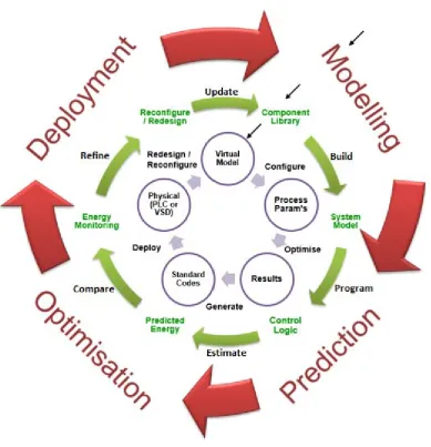
Figure 3.3: CBEO workflow………..43
Figure 3.4: Components classification in terms of their energy consumption……….………..46
Figure 3.5: Modelling Ready component considering its Idle losses………...……..47
Figure 3.6: Energy modelling verification process………51
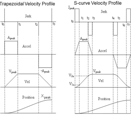
Figure 3.7: Trapezoidal velocity profile……….…53
Figure 3.8: Trapezoidal and s-curve velocity motion profiles………...54
Figure 3.9: Component modelling workflow in vueOne editor……….…59
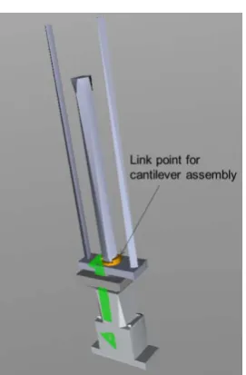
Figure 3.10: Link Point for assembled cantilever……….….60
Figure 3.11: Kinematics behaviour editor……….….…60
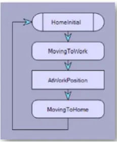
Figure 3.12: STD and its states and transitions……….…….61
Figure 3.13: Components assembly phase……….…62
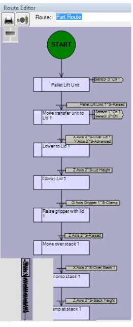
Figure 3.14: Work-piece routing logic……….……..63
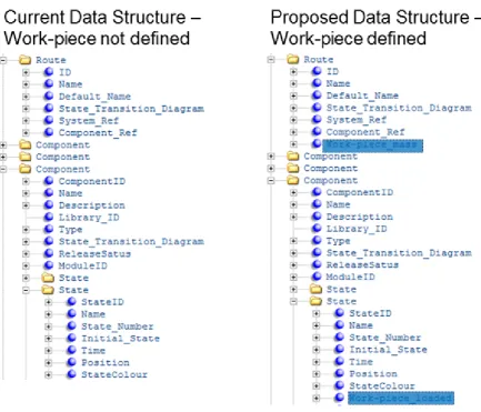
Figure 3.15: The proposed EnergyData to be added to vueOne data structure……….……66
Figure 3.16: Matlab code to predict the developed torque by actuator component………..…….66
Figure 3.17: Current and proposed motion definition……….……...67
Figure 3.18: The proposed motion data to be added to vueOne data structure……….…….67
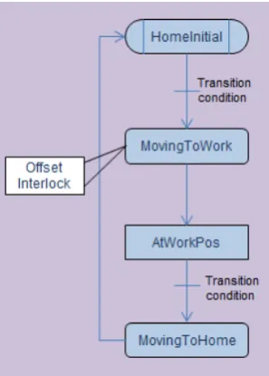
Figure 3.19: Proposed offset interlock in STD of actuator components……….……...68
Figure 3.20: Proposed change to Sequence Interlock data structure……….…….69
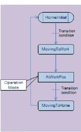
Fig. 3.21: Proposed mode of operation tag in static states of actuator STD……….…….70
Fig 3.22: Proposed change to static state data structure……….……70
Fig 3.23: Proposed change to work-piece routing data structure……….……..71
Figure 3.24: Energy prediction tool integration with vueOne tool………72
Figure 3.25: Conceptual energy optimisation software architecture……….….73
Figure 3.26: Flow diagram of Energy Engine………74
Figure 3.27: Proposed enhancement to vueOne tool………..76
Figure 3.28: The existing cycle diagram………77
Figure 4.1: Automation System Workbench (ASW)……….82
Figure 4.2: 18650 form-factor cylindrical cells being assembled………..83
Figure 4.3: Lid 1 to be picked up by the gripper and then placed on the top of sub-module 1……….…….……84
Figure 4.5: Station 4 sequence of operation………...85
Figure 4.6: ASW hierarchy………...……….85
Figure 4.7: suggested trapezoidal velocity profile……….87
Figure 4.8: suggested triangular velocity profile………...87
Figure 4.9: Electrical wiring of SMC motor controllers………90
Figure 4.10: Voltage and current wiring required on Voltech PM6000 channel per motor controller……..……90
Figure 4.11: Established wiring of power measurement devices to station 4………91
Figure 4.12: vueOne Energy Optimiser tool front panel………92
Figure 4.13: vueOne Energy Optimiser main tabs and sub-tabs………93
Figure 4.14: Actuator specification sub-tab………...………94
Figure 4.15: Motor & operation conditions sub-tab………...94
Figure 4.16: Power transmission sub-tab………...………95
Figure 4.17: X axis Actuator energy sub-tab………...………..95
Figure 4.18: Base actuators tab………..97
Figure 4.19: System energy tab……….……….98
Figure 4.20: Original motion data of X axis in controller software……….……100
Figure 4.21: Trapezoidal motion data of X axis in controller software………...…101
Figure 4.22: X axis energy consumption under optimised trapezoidal motion profile………102
Figure 4.23: Triangular motion data of X axis in controller software……….……103
Figure 4.24: X axis energy consumption under triangular motion profile………..…….104
Figure 4.25: Ready components energy consumption………..……105
Figure 4.26: Station 4 PLC networks responsible for switching Y axes into stand-by mode………..…106
Figure 4.27: Y1 axis energy consumption in idle and stand-by modes……….107
Figure 4.28: Y2 axis energy consumption in idle and stand-by modes……….108
Figure 4.29: X axis position rearranged in order to produce new station trajectory……….…...109
Figure 4.30: Peaks in energy consumption of actuating components due to same starting time………….……110
Figure 4.31: Station 4 PLC networks responsible for introducing time shift between axes……….…...111
Figure 4.32: Optimised station 4 energy consumption………112
Figure A.1: Fluke 1736 Portable Power Logger front screen………..123
Figure A.2: Fluke 1736 Portable Power Logger connection ports……….……..124
Figure A.3: Voltech PM6000 front view……….……….125
Figure A.4: Voltage and current wiring required on Voltech PM6000 channel per motor controller….………125
Figure A.5: Voltech PM6000 connection channels………..126
LIST OF TABLES
Table 2.1: Key characteristics of a reconfigurable manufacturing system …..………..………….…….17
Table 3.1: The vueOne toolset limitations and the proposed solutions………..………...78
Table 4.1: Station 4 actuating components………83
Table 4.2: Energy consumption by individual component of station 4……….96
CHAPTER 1
INTRODUCTION
1.1
BACKGROUND
Energy optimisation has become a very important topic in industry since the beginning of this century; shortage of energy resources, rising energy prices and strict regulations and legislations put more pressure on manufacturing firms to become more eco-friendly. Manufacturing industry is at the focal point of this new trend since manufacturing activities are the largest energy consumers and emission producers in the industrial field which also includes: the mining, agriculture, forestry, construction and fisheries sectors [82].
Energy cost rises globally due to scarcity of fuel accompanied by increase in demand which have led to increase in wholesale prices. Additionally enormous infrastructure investments are not carried out in an endeavour to accommodate environmental and climate change policies [7].
Existing manufacturing systems that do not comply with the new sustainability requirements will become obsolete due to governmental regulations and customer awareness. Upcoming manufacturing systems will certainly be founded on existing good practices and technologies. Future manufacturing must, however, deal with the pressing sustainability-related issues, forming new principles and characteristics. A life-cycle approach is needed to implement Sustainable Manufacturing systems, from raw material extraction, design, operation, and end-of-life. The negative impacts on the environment must be assessed properly by reliable sustainability metrics which can lead to the identification of optimisation opportunities and their implementation.
The automotive sector in particular has a pivotal role in this process since its factories are considered as high-intensity energy consumers and emission producers. Furthermore, the automotive industry stands as one of the most essential pillars of a modern economy. These facts show why advancements and shifts in manufacturing are often incited first by automotive firms. Automotive manufacturers have indeed adopted a range of sustainable practices and goals. For example; in 2016, Ford Motor Company has improved its global energy efficiency by 25% compared to that in 2010. The previous has been accompanied by reduction in CO2
emissions by 26.5% compared to 2010 figures [30].
levels by extending the capabilities of current virtual engineering (VE) tools that benefit from component-based approach. This is centred on better integration of currently non-coupled machine and process design parameters, energy prediction and optimisation methods, and energy monitoring and management techniques.
1.2
PROBLEM DEFINITION
It is currently very difficult to provide fairly accurate answers to some critical questions related to energy usage of a machine before it has been physically built. Examples of these critical questions can involve: what the peak usage will be, what opportunities there are for energy reduction via design changes or optimisation of the process. This situation is incompatible with dire sustainability needs and the increasing energy prices.
Even if a machine energy consumption is modelled, it is still difficult to know whether what has been modelled at the machine design phase is what will be consumed at the operation phase, as these are currently non-coupled engineering activities. Discussions with machine builders have highlighted that different machine designs can have very different energy usages. Thus, linking machine design parameters to energy requirements will enable machine builders to choose the most energy efficient operation, which is strongly needed in a readily applicable form.
Energy monitoring and management techniques, widely used in industrial plants to measure machines’ energy usage during the operation phase, are essential to identify the inefficiency in current manufacturing operations. However, relying on these techniques alone renders them often reactive, disruptive and incurring of preventable cost, time and risks. This has created a pressing need for proactive measures, at the machine design phase, capable of bridging the shortfalls of the former reactive practices.
1.3
RESEARCH MOTIVATION
The recent trend in industry in general and manufacturing in particular towards sustainability puts pressure on manufacturers to make their production facilities more environment friendly. The incentives of this trend are threefold: the environment, the society and the economy. These three incentives are interrelated as much as they are interdependent. When customers’ awareness has been raised to notice the negative impact of industry on the environment, governmental regulations that protect the environment has been put in place to ensure that manufacturers conduct their activities in an eco-friendly manner. Although there have been some improvements in this regard, there are more sustainability improvements to be achieved by the manufacturing firms.
It has been estimated that process and production optimisation with respect to energy consumption could save 15 – 20%, with another 16% savings expected to be attained by logistics optimisation [26]. These savings can be achieved by redesigning process plans, redesigning machine hardware and software, replacing machine parts by more efficient ones, replacing auxiliary parts with more efficient alternatives.
Virtual Engineering (VE) is one of the powerful technologies that is heavily involved in the industrial activities. However, it needs to be exploited to promote the energy efficiency of these activities. Since the late nineteen sixties, when computers started to contribute effectively to industry, engineers and computer scientists have progressively computerised all aspects of manufacturing operations across all levels.
By using VE tools, products can be designed and validated, processes can be planned and verified, and changes can be accommodated easily, quickly and efficiently. Therefore, the vision of this research is to create a framework that enables energy consumption to be accurately and quickly quantified for each and every step throughout the assembly system lifecycle and process development. This can be achieved if the design parameters and the required data are linked in a VE development tool. Hence, one can easily investigate alternative designs and make comparisons and alignments.
suppliers or machine builders. Current tools can reactively measure, monitor, analyse, manage and project the energy consumption data, but cannot proactively predict them in the early design phase, where most benefits can be achieved, which gives the proposed framework its value over the existing ones.
1.4
RESEARCH FOCUS
Automation Systems Group (ASG) at the University of Warwick has conducted research on the component-based approach for the development of manufacturing systems. Leading manufacturers, machine builders and automation suppliers such as Ford Motor Company UK, Jaguar Land Rover, Schneider Electric and Thyssenkrupp System Engineering have collaborated in this area of research. The primary objective of ASG research is to develop robust engineering approach to enable improving manufacturing systems within the automotive industry by developing the engineering tools shown in figure 1.1.
Component-Based Energy Optimisation (CBEO) framework has been created as a part of ASG research at the University of Warwick. The group has conducted research on component-based approach of automation lifecycle in manufacturing. A key aspect of this research is a 3D-based virtual engineering tool designed to virtually build production machines out of a generic set of components and to validate and optimise them before the physical build.
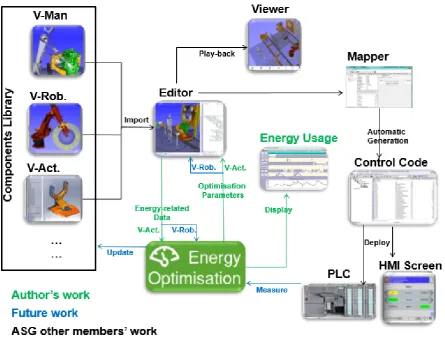
Figure 1.1: Development work conducted by the author, future work, and ASG other members’ work
The vueOne editor enables the machine designer to create virtual components by defining their physical geometry and control behaviour, and then assemble them to build complete manufacturing systems. The modelled components are stored and retrieved from the Component Library. V-Rob, which mimics the operation of industrial robots, can be added to the manufacturing system model, as well as V-Man, which mimics human operators in manual and semi-automatic manufacturing operations. Energy optimisation tool requires the energy related data of the actuator components in the modelled system in order to predict their energy consumption and then apply the optimisation parameters into the virtual system.
To validate the energy-optimal virtual machine modelled in vueOne editor, vueOne viewer visualises and plays back machine operations in 3D format. Once the machine is validated, its predicted energy consumption can be displayed, and the PLC and HMI screen can be automatically generated and deployed into a physical PLC.
Component Library. Detailed explanation of Energy Optimiser tool design and operation is available in sections 4.4 and 4.5.
The research presented here includes the development of a framework which will support profound understandings of the implementation of a more energy efficient manufacturing operations. This framework features the provision of an eco-friendly platform that allows interaction between various components throughout the machine life-cycle and across process development levels.
The specific contribution of this research is to develop and implement the CBEO framework and its Energy Optimiser tool. It seeks to achieve this by integrating currently non-coupled energy monitoring techniques and energy modelling and optimisation methods at the component and machine levels, on the basis of the established Internal Model Control (IMC) theory, and by benefiting from and extending the powerful capabilities of the VE technology. Furthermore, in order to benefit from CBEO framework, virtual industrial components must have energy-related characteristics such as physical and kinematical characteristics which determine the consumed energy due to the desired motion profile, operation mode, trajectory and control logic behaviour. CBEO framework allows the representation of the predicted energy consumption of the real system regardless of its complexity.
The Energy Optimiser tool results are validated by comparing them with the actual measurements on the shop floor. This validation allows profound insights into the components influence on the operational status of the overall system, and the need for the proposed CBEO for tuning to get the best possible results that fulfil processes requirements.
Finally, the CBEO should be fully integrated with the virtual engineering tool, veuOne, developed by ASG in order to exploit and extend its well-defined modelled components. Once this new validated feature is added to the existing veuOne for virtual visualisation and process planning purposes, the same energy information will be available and reusable to predict the energy consumption for any new machinery and hence facility to be built up from these components at any level of process development. Ultimately, following this argument, an important sustainable manufacturing requirement can be met.
1.5
RESEARCH HYPOTHESIS
The core hypothesis of this research is that: if energy consumption of a machine is accurately predicted and then optimised within a VE tool at the design phase, the manufacturing activities of this machine will fulfil the requirements of sustainable manufacturing at the operation phase. In other words, since machine design and operation parameters are well-coupled within such a VE tool, the predicted energy consumption of the machine at the design phase should closely match the measured consumption at its operation phase.
Furthermore, the same energy practice information of the machine components can then be (re)used to optimally parameterise the same machine to be reconfigured/redesigned, or a new machine to be designed and built using some or all of these well-defined components.
1.6
RESEARCH AIM AND OBJECTIVES
The purpose of this work is to improve the efficiency of assembly machine activities to fulfil the next-generation sustainable manufacturing requirements. In order to build a framework for sustainable manufacturing that is able to minimise the energy consumption during machine operation, there is a high need to extend the capabilities of the component-based approach and VE tools to include energy related data of the components and processes.
Through the development this framework, the author aims to promote best practices for system reuse, energy efficiency and modularity towards rapid responsiveness within the sustainable manufacturing domain.
The research objectives are listed below:
1. Examine and identify the common features of the existing approaches and practices to energy efficient manufacturing and their implementation and shortfalls.
2. Define suitable logical abstractions that are required to best address end-user requirements.
3. Adopt an approach that supports the reuse of modular machine components for improved energy efficiency.
5. Develop a novel proactive, comprehensive and applicable energy prediction and optimisation framework to improve the efficiency of assembly machines throughout their lifecycle.
6. Develop a novel engineering tool for energy prediction and optimisation at the component and machine levels.
7. Implement a prototype system to validate the developed framework and its tool, hence the research objectives.
1.7
RESEARCH METHODOLOGY
A brief description of the phases of this research is listed below:
Phase 1 – Literature and technology review
The first period of this research was spent in reviewing and critically analysing the academic literature and industrial practices and technologies in order to accurately define the problem and identify the gap between what the need is and what is available to fulfil this need.
Phase 2 – Specifications development
Specifications, features and outcomes of this research and the developed CBEO framework have been driven by industrial requirements. Valuable discussions and meetings were held with manufacturers, machine builders and system integrators, and automation suppliers to identify the requirements.
Phase 3 – Methodology development
In this phase, a proactive, comprehensive and readily applicable CBEO framework has been developed to bridge the gap between end-users’ requirements for energy efficient assembly machines and the current reactive engineering practices. The proposed CBEO framework has been further developed into an engineering tool to enable energy prediction and optimisation of assembly machine throughout its lifecycle.
Phase 4 – Application verification
compare the virtually predicted and optimised energy consumption with real machine consumption.
Phase 5: Evaluation and future improvements of CBEO framework
In this phase, the outcomes of the evaluation process enabled the author to highlight a number of issues to be improved within the proposed CBEO framework before it gets fully integrated to the vueOne VE tool.
CBEO has been tested by doing a number of experiments on the SMC station and comparing the results with the ones that were predicted. A number of different scenarios have been implemented to capture different factors that have influence on energy usage.
1.8
THESIS STRUCTURE
The rest of this thesis is structured as follows: chapter 2 describes the current problem and need, and critically reviews the industrial practices and relevant research. It also identifies the limitations of current manufacturing practices. To overcome these limitations and fill the gap between business requirements and current practices in the context of sustainability, chapter 3 proposes a holistic framework based on the IMC theory. This proposed state-of-the-art framework integrates reactive engineering activities with non-coupled optimisation methods. For proof of concept and evaluation of proposed framework, chapter 4 analyses and compares the actual measurements and the predicted results of the machine under study. Finally, chapter 5 summarises the work conducted in this research and highlights potential improvements and future directions.
CHAPTER 2
2.1
INTRODUCTION
Manufacturing systems simply transform raw materials into products using physical mechanisms. They survive only if they gain value which could be income, reputation and so on. They function to meet customers’ requirements by manufacturing the required products [28]. Over the last century, the manufacturing industry has witnessed the emergence of several paradigm shifts to cope with the evolving economic, social and recently environmental requirements.
On one hand, more energy is constantly needed to perform the industrial and, in particular, the manufacturing activities. On the other hand, this demand raises the worldwide concern about the dire environmental issues, such as climate change and depletion of natural resources. In the near future, the demand for energy is strongly expected to increase around the globe. This increase will be accompanied by disappearing resources, and consequently the price of energy will raise. The industrial sector consumed about 54% of the total global energy in 2016, more than any other sector [13]. Thus, higher energy efficiency in the manufacturing systems could make a very important contribution to reduce the industrial sector share of energy consumption, and, consequently, the bad impacts to the environment.
The existing component-based reconfigurable manufacturing system is strongly nominated to potentially contribute to the formation of the future eco-friendly, sustainable manufacturing system. Its characteristics give it the potential to help meeting the requirements for sustainability.
2.2
MANUFACTURING SYSTEMS PARADIGMS
A manufacturing paradigm, according to Koren, is a revolutionary integrated production model that arises in response to changing societal and market imperatives, and is enabled by the creation of a new type of manufacturing system [53].
The modern manufacturing industry has undergone several manufacturing paradigm shifts induced by changes in customers’ requirements and changes in the complexity of the manufacturing environment [20]. Each paradigm has its own imperatives, enablers and principles. Developing a new paradigm, which meets new requirements and has the capacity to deal with the limitations of the existing paradigms, essentially relies on a new enabling technology, and then allows new imperatives to be addressed.
Many manufacturing paradigms have been introduced since the so called the industrial revolution. It is inaccurate to say that one paradigm is better than another without taking into account a specific situation in a specific enterprise. In order to understand the need of any new paradigm, one must first understand the principles, imperatives and enablers of the existing ones. Hence, one may consider the following widely adopted paradigms: 1) mass production, 2) lean manufacturing, 3) mass customisation, and 4) reconfigurable manufacturing, in order to analyse their characteristics and limitations, and therefore, their contributions to enable, the sustainable manufacturing paradigm.
[image:27.595.72.503.491.740.2]2.2.1 MASS PRODUCTION
The operation of producing the highest possible standard of goods at the lowest possible cost using single-purpose machines was recorded in ancient Greece. This kind of manufacturing practice took more defined shape from the eighteenth century in England and then Europe. Over the last century, it had been the undisputed manufacturing behaviour till the late sixties [77].
The main principles of mass production manufacturing can be listed down briefly [19]:
Dividing carefully the whole production operation into simple, repetitive, specialised hand-free tasks.
Standardising the components or parts to allow the large production runs of parts that are readily fitted to each other without adjustments.
Using single-purpose machines with specialised materials and processes to minimise efforts required and maximise the output per unit of investment.
The major disadvantage of the mass production systems is they are inherently inflexible; if any unplanned situation occurs, then the system may encounter serious problems to accommodate it and may lead to severe consequences, primarily, high increase in the cost. For an instance, as the system is designed to work most efficiently at a specific rate, if the required production level goes below this rate, machines and labours are being inefficiently used. On the other hand, if the level goes over this rate then labours work overtime and machines maintenance cannot keep up leading to breakdowns.
From the energy consumption perspective, over half of consumed energy goes to non-productive activities (start-up, shut-down, idle, etc.), in mass production systems. It is reported that the energy consumed by non-manufacturing activities may reach to 85% of the actual whole energy required to manufacture a product [63, 18, 58]. This implies that a significant amount of energy could be saved by employing better system-level operational planning and machine-level energy optimisation.
2.2.2 LEAN MANUFACTURING
cultural differences induced the Japanese manufacturers, after deep understanding of mass production techniques, to think about alternative practices.
The concept of producing a large variety of products in small volumes with minimum non-value-added waste, which gives this system the name ‘Lean’, gradually emerged as the Toyota Production Systems started in 1948. Their multi-purpose machines enabled them to achieve this in a competitive manner by 1960, with customers able to demand more than a basic product [67].
Lean is a philosophy about delivering value from the customers’ perspective, eliminating waste and continuously improving processes. Lean production systems aim at optimising objectives like cost, time and quality. Lean management is based on four principles [89]:
Rather than producing as much as possible, customer demands pull goods or services through the manufacturing process. This minimises overproduction, inventory and ultimately working capital.
Focusing on one single piece at a time minimises work in progress, process interruptions, and lead and waiting time while increasing quality and flexibility.
Takt: Is how fast it is needed to manufacture a product to meet customer demand. Takt allows the balancing of work content, achieving a continuous flow and responding flexibly to changes in the marketplace.
Mistakes happen but a lean system does not pass on defects from previous steps, they must be fixed before going on.
2.2.3 MASS CUSTOMISATION
Mass customisation (MC) is a production strategy focused on the broad provision of personalized products and services, mostly through modularised product/service design, flexible processes, and integration between supply chain members [37].
From the costumer perspective, MC aims to provide customer satisfaction with increasing variety and customisation at reasonably low cost and with short lead time [84]. From the manufacturer perspective, MC aims to achieve a balance between product standardisation and manufacturing flexibility. By adopting the MC technique, manufacturers are able, to some extent, to stay competitive in a more uncontrolled and unstable global market.
The huge leap in the computer science in the 1980s played a key role in the manufacturing industry. This role can be noted in using numerical control machines, general-purpose automation and industrial robots that significantly increase systems flexibility. Computer-Aided Design/Computer-Computer-Aided Manufacturing (CAD/CAM) allows more rapid product and process designs and modifications generated to response to customer requirements [71]. Implementing the MC has double-side effects on the environment sustainability. On one hand, a product is only manufactured after receiving an order from the customer, a so called make-to-order business model principle, which means overproduction is fundamentally prevented. This results in lower energy consumption for the overall production in comparison with the mass production [72].
On the other hand, the variety of products offered by the MC requires high process flexibility. The high number of different manufacturing processes, makes the MC difficult to be optimised with respect to energy consumption [25]. It is therefore difficult to judge whether the MC manufacturing systems are eco-friendly or not.
2.2.4 RECONFIGURABLE MANUFACTURING SYSTEMS
reacted to these changes by proposing a new form of scalable and reconfigurable manufacturing system [54].
According to Bi [23] an RMS has an ability to reconfigure hardware and control resources at all of the functional and organisational levels, in order to quickly adjust production capacity and functionality in response to sudden changes in the market or in the regulatory requirements. The concept of an RMS is also similar to the concept of component-based manufacturing systems [44]. RMS aims to provide the functionality and the capacity that is needed when it is needed; i.e. both its functionality and capacity are not fixed like other systems. RMS basic principles are [54]:
The RMS is designed for adjustable production resources to respond to forthcoming needs. The RMS capacity is rapidly scalable in small, optimal increments. The RMS functionality is rapidly adaptable to the production of new products.
To enhance the speed of responsiveness of a manufacturing system, core RMS characteristics should be embedded in the whole system as well as in its components (mechanical, communications and controls).
The RMS is designed around a part family, with just enough customised flexibility needed to produce all parts in that family.
The RMS contains an economic equipment mix of flexible (e.g., CNC) and reconfigurable machines with customised flexibility, such as Reconfigurable Machine Tools, Reconfigurable Inspection Machines, and Reconfigurable Assembly Machines.
The RMS possesses hardware and software capabilities to cost-effectively respond to unpredictable events — both external (market changes) and intrinsic events (machine failure).
Table 2.1 below shows the key characteristics of RMS.
Table 2.1: The key characteristics of the reconfigurable manufacturing system [61]
1. Modularity Design all system components, both software and hardware, to be modular.
2. Integrability Design systems and components for both ready integration and future introduction of new technology.
4. Diagnoseability Identify quickly the sources of quality and reliability problems that occur in large systems.
5. Customisation Design the system capability and flexibility (hardware and controls) to match the application (product family).
6. Scalability The ability to change the machines’ production throughput by altering or augmenting the component in the machine.
Among various technologies and processes that enable RMS, open-architecture control (reconfigurable software) and modular machines (reconfigurable hardware) are substantial enabling technologies [62]. Section 2.5 explains how the Sustainable Manufacturing System gains benefits from the RMS.
2.3
THE NEED FOR SUSTAINABLE MANUFACTURING
Today both manufacturers and costumers are becoming more conscious about the environment; both of them really do understand the problem and start to behave more responsibly. Although the vast majority of small and medium enterprises (SMEs) have not yet addressed sustainability because of their short-term survival issues, the efforts of some high volume manufacturers, such as automotive manufacturing firms, have shown tremendous improvements. For instance, in 2013, Ford Motor Company announced their goal to minimise their facilities’ CO2 emissions
by 30% by 2025, compared to 2010 baseline, building on the 31% reduction they achieved from 2000 to 2010. Furthermore, Ford managed to reduce their facilities’ water usage by 62% from 2000 to 2012. Also Ford reduced the amount of waste sent to landfill by 40% from 2007 to 2011, and the energy consumption of their worldwide facilities by 30% from 2008 to 2013 [29].
Several initiatives on more energy efficient manufacturing are on-going. For example, the European Commission has put in place its Environmental Action Programme to 2020 in order to tackle the persistent sustainability challenges until 2020 as a prelude to the 2050 vision of a prosperous and healthy environment [5]. In this context, improving the energy efficiency of both small and medium enterprises (SMEs), and high volume manufacturers can help effectively to attain this vision. On the other hand, manufacturing systems that do not comply with the increasingly stringent governmental regulations, and the increasing customers’ awareness of the environmental issues, will become obsolete.
There are many motivations and drivers to behave in an environment-friendly manner can be generally summarised in five drivers:
Shortage of natural resources: Fossil fuel is the main source for world energy supply; oil supplies are estimated to last another 26 years assuming continuous compound consumption rate, similarly gas and coal for 28 years and 98 years respectively [80]. The situation gets worse if this rate gets increased because of every nation is ambition for economic growth.
Global warming: There is a little debate that the Earth will warm during this century as a result of fossil fuel combustion. The Intergovernmental Panel on Climate Change (IPCC) has identified exponential increases in atmospheric concentrations of CO2 as
the dominant forcing agent for global warming [2]. Although expectations of the extent
of this warming are primarily limited, the following equation ∆ λ5.53 ln / ₒ
forecasts the change in the global surface temperature, where ∆ is the temperature increase at a given year relative to a reference year; and ₒ are the CO2
concentrations at that given year and in reference year respectively. The λ coefficient is the climate sensitivity; λ can assume values between 0.3 and 1.3 [2].
Pollutions: Manufacturing activities generate considerable amounts of waste that are in main landfilled, discharged into surface water or burned causing dangerous health and environmental consequences. In 2014, official statistics shows that 11.12% of the total waste, 36.5% of greenhouse gas emissions, the European Union zone (EU-28) were generated by manufacturing industry [8].
to increase in human activities which in turn increases depletion of more resources to meet their demands. This increase will lead to increases in wastes and emissions.
Legislations and regulations: Since manufacturing operations are getting more deleterious to humankind and the environment, governments around the world are getting actively involved in the development of manufacturing systems that are able to limit these negative impacts. The point behind this governmental move, is to bring all parties (manufacturers, costumers, environment, etc.) into win-win situations, by funding researches and studies on sustainability, offering grants and prizes to industrial firms and raising the awareness of customers on one hand, and mandating eco-friendly regulations and legislations, revisiting standards and the requirements, and banning materials and processes in other hand [41].
2.4
SUSTAINABLE MANUFACTURING SYSTEM
According to the United States Department of Commerce, sustainable manufacturing is defined as the creation of manufactured products that use processes that minimise negative environmental impacts, conserve energy and natural resources, are safe for employees, communities, and consumers and are economically sound [11].
Sustainable Manufacturing Systems (SMS) involves complicated interactions between the environment, the economy and the society, and impacts on all of them. This is not only about environment-friendly products or processes; supply chain, enterprises, facilities, processes and products must also be considered in this manufacturing system. In this research we focus on the environmental aspects of sustainability, and the manufacturing activities at the machine level.
2.4.1 SUSTAINABLE MANUFACTURING METRICS
SM indicators ideally should help the manufacturer to monitor progress over time, take actions against problems to improve performance, and identify any considerations that may be missing from earlier analysis to help get a fuller picture.
Currently there are no internationally agreed metrics for the SM. Moreover, there is a lack of any inclusive, open and neutral metrics for the SM. Selecting such metrics, that will inform performance analysis, is not a straight forward process like economic metrics selection, such as unit cost. Some initiatives have been carried out by some academics, international corporations and international organisations in this context. For example:
Organisations: The Organisation for Economic Co-operation and Development (OECD) Toolkit [11], provides eighteen quantitative indicators (e.g. P2 recyclability (Products), O1 water intensity (Operations), I2 restricted substances intensity (Inputs) and so on) to help measuring the environmental impact of single facility activities for all types of manufacturing. However, some of these indicators can be extended to measure supply chain related impacts, and if the manufacturer wishes to measure the environmental impact at the overall enterprise level, then individual facilities indicators can be aggregated.
Corporations: Ford Product Sustainability index PSI [10], it is the first index in the automotive sector. It provides eight (e.g. global warming, safety and cost) indicators that yield a result (non-single value) in line with the international standards such as ISO 14044:2006 Life-Cycle Assessment (LCA) standard. It measures the lifecycle environmental impact of the final produced vehicles.
Academics: Reich-Weiser has suggested measuring SM in terms of energy scarcity, energy independency, material scarcity, water availability and climate change .It follows the ISO 14044:2006 standards on LCA [74].
2.4.2 LIFE‐CYCLE ASSESSMENT (LCA)
The LCA is a compilation and evaluation of the inputs, outputs and the potential environmental impacts of a system throughout its lifecycle [6]. The ISO 14044:2006 international standard (first released in 1997, last reviewed and confirmed in 2016) defines the environmental impacts of products LCA.
assessor to model the enterprise from which the products are manufactured or in which processes operate. It allows the decision makers to make quantitative comparisons, which in turn allow them to more fully understand the risks, opportunities and trade-offs among the phases and the different impacts that occur at each phase.
LCA has four basic elements [52]:
1) Goal and scope definition (G & SD): It is like an introduction in which the valid rules for a specific LCA study are defined.
2) Inventory analysis (LCI): It models the system according the requirements come from G & SD.
3) Impact assessment (LCIA): It contains the impact categories that are subject to evolution.
4) Interpretation: According to ISO 14044:2006, phase of life cycle assessment is where the findings of either the inventory analysis or the impact assessment, or both, are combined consistently with the defined goal and scope in order to reach conclusions and recommendations.
Figure 2.2 shows the aforementioned four elements.
Figure 2.2: Elements of LCA (ISO 14044:2006)
2.5
PARADIGM SHIFT TOWARDS SUSTAINABLE
MANUFACTURING
The requirements of the SM paradigm are unprecedented. The existing manufacturing paradigms have been developed for the sake of the conventional manufacturing requirements (cost, quality, time, etc.) but not for sustainability requirements. Although none of them meets the sustainability requirements, the existing paradigms are definitely going to contribute to any forthcoming and promising sustainable manufacturing paradigm.
Figure 2.3: From the RMS paradigm to the SMS paradigm [20]
2.6
VIRTUAL ENGINEERING AS AN ENABLING TECHNOLOGY
The virtual engineering (VE) technology has evolved enormously over the last few decades, empowered the industry with powerful, fast and cost-effective tools for most aspects of product and process developments. Hence achieved high levels of competiveness. They can allow accurate evaluations in reduced time, cost, risk and effort [79].
The VE models can “mimic” or simulate a target system’s (or object’s) behaviour, response, appearance, and/or geometry with a degree of realism comparable to the actual system or object [27]. From the manufacturing system perspective, VE is typically utilised as described in the following sub-sections.
2.6.1 MODELLING AND SIMULATION
Simulation can be used to resolve many of the uncertainties in the decision making process by representing the modelled system at various levels of abstraction. It also allows to investigate seamlessly, rapidly, and at low cost possible alternatives throughout the lifecycle.
2.6.2 PROCESS PLANNING
Process planning is an important application of the VE. It can give precise and clear visualisation of the sequence of machine operations and the layout i.e., how the product is to be moved and manufactured in a manufacturing facility [73]. Using product and resource data, VE tools can help create and validate the initial process plan, modify the plan for specific requirements, connect the product and resources to process steps, and carry out standard time studies and assign the job equally between resources. The operational sequence can then be visualised in a 3D format.
Considering Body in White (BIW) assembly planning for the automotive industry as an example, a 3D process planner enables system design and validation. Working directly with product data from engineering, BIW assembly planner can deliver to suppliers accurate 3D manufacturing assemblies of parts and assigned fasteners, sending early feedback to the design team about critical fasteners ensures that all weld points can be reached with a minimum number of weld guns keeping cost under control. The planner can then distribute all manufacturing assemblies and spot guns across the stations of a production line to maximise individual station capacities and minimise the overall cycle time [3].
2.6.3 VIRTUAL COMMISSIONING AND DEPLOYMENT
The objective of using the virtual commissioning is to optimise and debug the control system. During virtual commissioning, control logic is extensively tested including functions for emergency, safety, tracking, conditions check, communications and abnormal cases to avoid any risk of damage to real facilities. A practical study showed that 75% of the conventional commissioning time was saved by using the virtual commissioning first [46].
Once the virtual system operates satisfactorily with no faults and as planned, the control codes can then be downloaded to the physical target devices (PLCs, HMIs, motor drives, etc.).
2.7
CURRENT INDUSTRIAL PRACTICE FOR ENERGY
OPTIMISATION
Reducing the energy consumption is increasingly becoming one of the top priorities for manufacturing industry. In 2016, the United Kingdom industrial sector consumed 17% of total energy [87]. Changing the nature of manufacturing procedures and techniques offers promise of more efficient and sustainable industry. Such change is being stimulated by several factors and incentives such as rising in energy costs and dynamic pricing, and climate impacts. In order to identify the opportunities for energy optimisation for future manufacturing, understanding, investigating and evaluating the existing practices are perquisites. This understanding comes from monitoring, archiving and visualising consumed the energy consumption data. The operational energy data and historical reports can be used to analyse and then identify where potential efficiency improvements are needed.
Industry is using a number of methods and tools to identify the opportunities for energy optimisation. A brief overview of the most common practices that currently used in industry to monitor and optimise the energy consumption is given below.
2.7.1 ENERGY MONITORING
The energy consumption cannot be optimised unless it is measured and monitored. Several technologies that collect the energy data are being provided to manufacturers and machine builders by automation suppliers.
In addition, Human-Machine Interface (HMI) screens can be used to visualise the energy consumption at the machine, production line and plant levels. Some automation suppliers provide devices (e.g. circuit breakers and overloads) that can measure the energy consumed by various devices, thus allowing the mapping of energy consumption over a plant.
2.7.2 ENERGY MANAGEMENT
Energy Management: Referring to ISO 50003:2014 [4], energy management includes all the measures that are planned and implemented to ensure minimum energy consumption. The Energy Management System (EnMS) systematically records the energy usage and serves as a basis mainly for investments in improving the energy efficiency. The EnMS helps manufacturers to comply with the energy policy and to continuously and systematically improve its energy performance.
Energy management, according to the ISO 50003:2014, follows the PDCA (Plan, Do, Check, Act) cycle. The PDCA cycle provides a framework for the continuous improvement of processes or systems. It is a dynamic model; since the results of one cycle form the basis for the next one. This structure enables the continuous reassessment and optimisation of energy consumption with the goal of progressively reducing the cost.
Plan: Establishing energy-saving targets, determining the strategy, identifying measures and responsibilities, providing the necessary resources, preparing the action plan.
Do: Establishing management structures for maintaining a continuous process, undertaking improvement measures (for example efficient technologies/procedures).
Check: Reviewing the level of target achievement and the effectiveness of the EnMS, collecting new ideas via energy audits. If necessary, consulting an external expert.
Act: Strategic optimisation by consolidating the current energy data, audit results and new information, evaluating the progress with the help of current energy market data, deriving new objectives.
2.7.3 ENERGY-EFFICIENT SCHEDULING AND PLANNING
This technique aims to associate each operation of a machine/line to its consumed energy. An optimum environmentally-oriented system-level scheduling and planning framework has not yet emerged but research in this direction is ongoing [58].
Some strategies are currently performed in the industry, such as load balancing, load shifting and sleep/off modes. Other strategies include switching some non-critical systems off in the case the overall energy usage is about to exceed the pre-set power usage threshold, run the most efficient production line based on operation efficiency, certainly, besides the production cost, and run the machines/lines at lower speed, or increasing their speed to maximise the productivity against time, labour and energy [12].
Other application for energy data records that they could help proactively in detecting the potential problems caused by potential machine/line based on the energy profile signature. It is vitally important strategy in case this excess in usage leads to break down some other machines or lines due to lack of power.
2.7.4 NETWORKED ENERGY MANAGEMENT
The ODVA (Open DeviceNet Vendors’ Association) is investing significant efforts to define an Energy Management object to be added into its CIP (Common Industrial Protocol) objects’ attributes, aiming to measure and reduce energy consumption both during idle time and production. An interoperable Energy Profile is also deployed to benefit customers who deal with different devices from different vendors. An Energy Profile is a way to easily identify energy capabilities that are implemented in a device. It defines energy and power related objects [24].
In case of bottle-neck or breakdown, weekends or shift change, or any other idle time, a Power Management object can be used to commands devices/machines/lines via a suitable controller or software to enter low-power modes. An Energy Management object can be utilised to prevent demand peaks during production. This operation typically happens hierarchally from small energy management clients at device level into typically machine, line and whole system level to manage the overall energy consumption [24].
robot assembly cells, laser cutters and paint lines) to be managed over a PROFINET network. It controls energy usage during planned and unplanned breaks in production [9].
2.7.5 CURRENT ENERGY MANAGEMENT TOOLS
B.Data from Siemens, PMCS from GE, 4EE from Rextroth and PlantStruxture from Schneider are examples of the existing tools in the market. Few of the existing tools offer advanced functions beyond the basic monitoring, archiving, visualising and reporting functions. The advanced functions are capping power peaks, load balancing and computing projected energy costs.
It is worth noting that the aforementioned current industrial practices are considered as passive or reactive techniques, since they aim to reduce the energy usage of already established systems later at the operation phase. These fundamental characteristic makes these techniques are often disruptive, incurs more cost, time, effort and risk. Therefore, predicting and optimising the energy to be consumed by the envisioned system proactively at its design phase is expected to result in more energy and operational cost savings.
2.8
CURRENT ACADEMIC RESEARCH ON ENERGY
OPTIMISATION
Ongoing research in academia is investigating the energy optimisation opportunities from different viewpoints. Here we summarise new research at the component/machine level that are not yet been implemented in the industry. It is worth noting that, the production line level is not reviewed here as it is out of the scope of this research. The main optimisation themes are idle time optimisation, path optimisation and acceleration optimisation.
2.8.1 IDLE TIME OPTIMISATION
In the case of complete shut-down, enough time should be allowed to switch the component back on before the beginning of its next task. To enable this inclusion, machine builders and automation suppliers should incorporate the required simple technological features in their components/machines [38].
2.8.2 MOTION PATH OPTIMISATION
A motion trajectory is defined by Riazi as a sequence of sampled robot machine poses at a given sampling rate. Each sample includes current position of the axes, the pose, and the specific time instance when the robot/machine reaches the pose. The path of a trajectory is defined by the sequence of poses that a trajectory follows, but without including the time instance when a pose is reached [76].
Servo-actuated mechanisms, including robots, are widely deployed in manufacturing due to their flexibility in adopting various programmable motion trajectories to suit the production goals. Energy-optimised trajectories for single and multiple degree-of-freedom mechanisms and manipulator systems have been proposed [40]. Several cost functions have been developed taking in account the dynamic and process constraints [68]. For instance, improving the energy efficiency of pick-and-place robot by means of time-scaling trajectory has been discussed, starting from the fact that 15-20% of the total working time of industrial robots in automotive industry is spent on Homing [69].
2.8.3 ACCELERATION OPTIMISATION
As with all the optimisation methods, software changes are typically desired but if the hardware does not support them, such as a motor drive that does not support the suggested more energy-efficient motion profile, then hardware redesign is necessary.
2.9
ENERGY CONSUMPTION PREDICTION AND MODELLING
Machine builders are required to include accurate energy consumption data in their components, machines and lines to enable their customers to manage operational costs and environmental performance during the operation. Unfortunately, there is no such robust tool in the market that can predict the energy consumption at the design phase at the component, machine or line levels. The importance of such a tool is its capability to examine different alternatives at the design phase, and then choose the most energy efficient design to be built. Considerable efforts have been invested by many researchers in order to model or predict the energy usage of manufacturing machines. The existing energy consumption modelling can be classified into five main methods, which are described in the next sub-sections. The energy modelling methods are 1) mechatronics modelling, 2) power flow diagram, 3) thermal modelling, 4) mathematical modelling and 5) state-transition modelling.
2.9.1 MECHATRONIC MODELLING
Aims at deep understanding and accurate optimisation of the energy consumed in the physical system. Although it is an accurate method, yet it has limited applications because of very detailed parameters required. Also, it cannot be scalable or used generically in most cases [33].
In order to model the system accurately, the components behaviours, their interactions, their influences on the system performance, etc. should be well-known. Therefore the modelling process using this method is considered to be complex and time consuming [47].
2.9.2 POWER FLOW DIAGRAM
2.9.3 THERMODYNAMICS MODELLING
Thermodynamics modelling method determines the theoretical minimum energy required to achieve any manufacturing task. This value is determined based on the fact that each manufacturing activity has heat and work interaction with other activities involved in the same operation, and with the surrounding environment in terms of reference pressure, heat and chemical compositions. Thus, the system behaviour can be modelled using the 1st and 2nd laws
of thermodynamics, and metrics, including the consumed energy [42].
This method also aims to understand and analyse the system efficiency based on Energy, of 1st
thermodynamics law, and the more accurate but complex, Exergy, of the 2nd law of
thermodynamics [50]. Although this method is effective in comparing the relative efficiency of different manufacturing systems, it has limited applications as it needs hard to attain, unattainable or even unknown parameters [78, 70].
2.9.4 MATHEMATICAL MODELLING
Mathematical modelling aims to optimise the energy consumption of a system by define it as a function of its working parameters. Response Surface Method (RSM) was used by Draganescu for this purpose, where number of experiments and iterations under different conditions for the same process, machines or lines were performed before processing the collected energy data mathematically, and finally the energy data were linked to the process parameters [35]. Although RSM can give good results in term of reducing energy consumption, it does not consider any physics involved to ease the modelling process. Hence, the terms appearing in such models have no physical meanings which limits any further investigation about system efficiency.
Jin outlines a mathematical model that can compute an environmental impact score for each machining operation based on the environmental impact of the materials used based on commercial database tools like ECO-SCAN [49]. However, it provides only vague score for environmentally impact that tells nothing about energy consumption.
2.9.5 STATE-TRANSITION MODELLING
Action-Oriented, Event-Driven, Task-Oriented modelling are other names in the literature for this modelling technique. It originates from the fact that the energy consumption of a system is strongly connected to its operating states [22], in other words energy consumption is dynamically depends on tasks variability within the manufacturing system.
Each type of production equipment has its own various operating states such as switch on/off, warm up, processing, idle, stand by, etc. and each of these states has its own energy consumption, some of them consumes fixed amount of energy like stand-by state, and some of them consumes variable amount of energy like processing state. Specific energy consumption per each production operation is independent of the nature of specific production task. Thus, every production operation can be described as a chain of operating states and their corresponding energy. Moreover, any set of state chains from either manufactured product or used equipment perspectives can be modelled and give the decision maker various operation alternatives for the desired manufacturing task. It is important to assign the equipment that will execute each process at scheduling phase as it has an influence on the resulted estimation of the required energy. Consequently, decisions like machine energy levelling and peaks capping can then be taken robustly [88].
Since this method formulates the consumed energy behaviour of the whole operation by considering the energy consumption at each individual operating state or event, it is considered to be generic, scalable to the system size and details required, considers how the system is being used, and needs small computational capabilities [33].
2.10
SUMMARY
On one hand, the academics have conducted a wide range of research areas under the umbrella of sustainable manufacturing; from introducing carbon emission signature of an individual manufactured part, to identifying the impacts of alternative machining strategies in numerically controlled (NC) machines on their energy consumption [17], and suggesting metrics to measure sustainability performance throughout system lifecycle and process development [74]. In fact, the methods that have been suggested so far deal with the targeted systems (components, machines or lines) as black boxes; as the energy consumption modelling carried out by measurements and experiments [22].
On the other hand, the current energy management practices in industry have been highlighted and discussed, and their shortfalls have been addressed. It is worth noting that typically machine builders and system integrators do not include accurate energy consumption data in manufacturing system to enable manufacturers to manage the operational costs and environmental performance. This is mainly due to the fact that there is no robust tool available in the market which can predict the energy consumption at the design phase, and examine different alternatives.
Research works on the energy optimisation of manufacturing machines have investigated the impacts of idle times, velocity profiles and mechanisms paths on the consumed energy. It is noted that these optimisation methods are non-coupled, and most of the time, been used individually. Therefore, these optimisation methods could be effective if they are integrated in one framework, and implemented throughout the lifecycle of manufacturing systems.
CHAPTER 3
3.1
INTRODUCTION
The literature review in Chapter 2 has stressed the importance of energy prediction throughout the manufacturing system lifecycle, especially at the design phase. It has also highlighted the efforts that have been invested in order to predict energy consumption in manufacturing operations. These efforts mainly aim at more energy-efficient operations and ultimately more sustainable manufacturing. However, the amount of energy that can be saved by implementing the current reactive practices can be maximised by implementing proactive practices for the reasons that will be detailed in this chapter.
The gap between what is needed to improve the energy efficiency of manufacturing systems, and what is offered by current practices has been identified in this work of research. Based on that, the author believes that the realisation of a proactive, holistic and readily applicable framework for energy prediction is a crucially needed step towards better energy optimisation, and consequently more environment-friendly manufacturing.
However, most of the available Virtual Engineering (VE) tools, which are heavily used throughout the lifecycle phases of manufacturing systems, do not provide the sufficient energy-related information that is necessary to predict and optimise their energy consumption. The reason behind this is that these VE tools are principally designed to perform their modelling, simulation and validation functions without taking into their account the environmental consequences.
Furthermore, the available energy modelling tools either require hard to attain information, or the developed models at the design phase cannot be further used at later phases of the system lifecycle. Also, it is often the case that none but one of all the energy optimisation methods is considered and implemented; that is ‘idle time optimisation’. Consequently, these tools and methods are not adopted in industry because of their lack of supporting the functional requirements.
![Figure 2.1: The evolution of the manufacturing paradigms [20].](https://thumb-us.123doks.com/thumbv2/123dok_us/9452868.452472/27.595.72.503.491.740/figure-evolution-manufacturing-paradigms.webp)