Please cite this article as: M. Doostizadeh, M. Ettehadi, A New Procedure for Reactive Power Market Clearing Considering Distributed Energy Resources, International Journal of Engineering (IJE), IJE TRANSACTIONS B: Applications Vol. 32, No. 8, (August 2019) 1134-1143
International Journal of Engineering
J o u r n a l H o m e p a g e : w w w . i j e . i rA New Procedure for Reactive Power Market Clearing Considering Distributed
Energy Resources
M. Doostizadeh*a, M. Ettehadib
a Faculty of Engineering, Lorestan University, Lorestan, Iran
b Faculty of Engineering, University of Torbat Heydarieh, Torbat Heydarieh, Iran
P A P E R I N F O
Paper history:
Received 25 October 2018
Received in revised form 05 May 2019 Accepted 05 July 2019
Keywords:
Benders Decomposition Distributed Energy Resources Power System Operation Reactive Power Procurement
A B S T R A C T
Traditionally, conventional generation units were used to provide ancillary services e.g. reactive power support, and spinning reserve. Nonetheless, with the emergence of highly penetrated distributed energy resources (DERs) systems and considering how beneficial they can be; it appears reasonable to use them as reactive power providers. Therefore, this paper introduces a new procedure for DERs to participate in the reactive power market. To do that, an algorithm is proposed to calculate the deliverable reactive power capability of DERs from distribution networks to transmission systems. Furthermore, a reactive power procurement model is introduced to consider DERs participation in the reactive power market. Finally, to show the effectiveness, and validity of this method many case studies are carried out on 33-bus distribution and CIGRE 32-bus transmission test systems
doi: 10.5829/ije.2019.32.08b.09
1. INTRODUCTION1
Ancillary services, like reactive power supply and spinning reserves, are crucial for the reliable, and safe operation of power systems. Therefore, there have been discussions regarding the secure/optimal provision of ancillary services during power systems operation for decades, especially about reactive power supply. With power system restructuring and the emergence of electricity markets, system operators have been encouraged to initiate/merge reactive power markets, where a fair competition in the reactive power provision sector is available for the suppliers [1]. However, because of the high reactive power’s losses over long distances, it is provided locally. Due to this localized aspect of reactive power, the full development of a competitive market is very challenging [2]. Correspondingly, a limited number of local providers may prevent competition and lead to market power. These suppliers can submit excessively high price offers or withhold supply to increase the market price to its advantage. As a result, reactive power markets have not
*Corresponding Author Email: [email protected] (M. Doostizadeh)
been fully developed all over the world and no unified and universally accepted framework is yet proposed for reactive power management [1].
To address these concerns, a uniform price auction based on a novel methodology is suggested, where it figures the optimal reactive power prices across the entire system. A pay-as-bid (PAB) market structure is proposed, where only market power holders receive higher payments; however, not only there are PAB structure deficiencies, but the market power problems also remain unsolved [3]. A localized reactive power market is introduced, which uses voltage control area concept to divide a large-scale power system into multiple smaller sub-systems where a uniform pricing is issued in each sub-system [4]. The proposed method reduces the power market impact on the corresponding areas, but it cannot be fully removed in some scenarios. A long-term contract-based reactive power market is proposed; but, since the network topology and market players remain constant in either long-term or short-term market, the powerful providers will still be able to enact market power [5].
meeting reactive power demands [6-8]. Furthermore, since most DERs are located at the distribution level, the required reactive power can be provided locally by these resources. Accordingly, few studies so far have explored DERs’ potentials in providing reactive power by participating in distribution level reactive markets [9-12]. A reactive market for medium voltage distribution systems is proposed by Madureira and Peças Lopes [10] to involve distributed generation units and microgrids in reactive provision. Similar to Madureia and [10], a clearing procedure for a reactive market considering wind turbine generators in distribution systems is proposed by Calderaro et al. [11]. A coordinated local control approach is presented by Rueda-Medina and A. Padilha-Feltrin [12] to obtain benefits of offering the voltage regulation ancillary service to DSO and maximizing allowable active power production for each DER unit. A VAr market at the distribution level is developed by Samimi et al. [13, 14], in which DERs could offer their reactive power prices and actively participate in the Volt/VAr control of distribution network.
Based on the literature, DERs can play an active role in reactive power provision at the distribution level. In this paper, advantage of RESs was motivated. We extended our previous, Doostizadeh et al. [15] presented an optimized algorithm, such that DERs can offer their reactive power capacity into HV transmission networks. To do so, a new procedure is introduced to calculate the deliverable DERs’ reactive power from distribution networks to participate in the reactive power market on the high voltage (HV) transmission networks. This is done by considering DERs’ reactive power capability and distribution network voltage security. Moreover, the method can offer a priority list to show the best reactive power dispatch scenario in a distribution system. Then, a reactive market model based on the proliferation of the players and the increased share of DERs at the distribution level is presented. The proposed market is cleared through a mixed-integer nonlinear optimization problem (MINLP). To solve the resulted MINLP optimization problem, Benders decomposition is employed.
Rest of the paper is on the following order: Section 2 presents DERs reactive power modelling. The proposed reactive power market is introduced in Section 3. Section 4 presents case studies to demonstrate the efficiency of the proposed method. Finally, Section 5 showcases the main findings of this study.
2. DERS’ REACTIVE POWER MODELLING
DERs’ impact on reactive power provision depends on their technology, and reactive power capability [7].
Broadly speaking, DERs and their technologies, can fit into two major categories:
• Power Electronic Interfaced DERs (PEIDERs): These DERs (e.g. photovoltaic cells, energy storage systems, fuel cells, etc.) are connected to the network with the help of power electronic interface devices. They can simultaneously produce active and reactive power, based on the control strategy used in PEIDERs. The fast response of PEIDERs makes them suitable to compensate for reactive power shortages immediately [9].
• DERs that are directly connected to the network: The output voltage and frequency of this type of DERs are designed to be capable of being directly connected to the network. These DERs are either a synchronous or asynchronous generator (e.g. squired cage induction generators (SCIGs) and doubly-fed induction generators (DFIGs)). SCIGs can only use reactive power, and not producing; thus, they cannot be utilized for network reactive power support [8].
Overall, all DERs technologies (except traditional SCIGs) can provide a fast, dynamic reactive power response (like a synchronous condenser), which can be useful for system operators during reactive power shortages. To make the best of these unique features, this paper models the reactive capability of various DERs first, and then a methodology is proposed to calculate the maximum deliverable reactive power by a DER at distribution-level to the main substation (HV transmission level) where the network criteria like voltage and power transfer limits, are enforced.
2. 1. DERs Reactive Power Capability To extract the capability of each DER, it is necessary to consider
the limitations that are enforced during
injection/absorption of power to/from the network. Thus, the reactive power production capability of different types of DERs in distribution systems are presented.
1) Directly connected DERs: The capability curves of a synchronous generator (SG) and a DFIG are respectively shown in Figure 1(a) and (b), and the following equations represent these curves limitation:
2 2 2 , g a i act
Q U I −P (1.a)
2 tan
g act
s U P Q
X
− (1.b)
(
) (
2)
22 g q s act g
s s
U E X P U Q
X X
− −
− (1.c)
(
) (
(
)
)
(
)
(
)
2 2
2 m g f a m act g
a m a m
X U I X X P U Q
X X X X
− +
−
Equation (1.a) represents the armature current limit of both SG and DFIG, where 𝑈𝑔 is terminal rated voltage, 𝐼𝑎 is the maximum armature current and 𝑃𝑎𝑐𝑡is actual
active power. Equation (1.b) denotes the under-excitation bound related to the steady-state stability of SGs, where 𝛿̅ is the maximum angle between the quadrature axis of SG and the terminal voltage, and 𝑋𝑠is
synchronous reactance. Equation (1.c) represents the rotor current limit of SG, where 𝐸̅𝑞is maximum internal
voltage. Equation (1.d) is the rotor current limit of DFIG, where 𝐼̅𝑓 is the maximum field current.
2) Photovoltaic (PV) units: The reactive power capacity curve of the PV generator is defined by current inverter limit, voltage inverter limit, and PV active power limit as depicted in Figure 2 [16]. The feasible operation region of a PV unit is gray marked. Therefore, the reactive power of PV is formulated as follows:
2 2 2
g i act
Q U I −P (2.a)
2 2
2
2 g g i
act
U U U
P Q
X X
+ + =
(2.b)
Equation (2.a) denotes the current inverter limit; where
𝐼𝑖 is maximum current injection by the inverter, 𝑃𝑎𝑐𝑡is
the power output of PV, and 𝑈𝑔 is the gride-side
voltage. The maximum voltage of PV inverter (𝑈𝑖)
imposes an additional limit on Q, and it is described by equation (2.b), where 𝑋 is the reactance seen from the inverter terminals.
Figure 1. Reactive capability curves: (a) SG, (b) DFIG [12]
Figure 2. Reactive power capacity of the PV unit [16]
3) Energy storage resources: The capability curve of an energy storage system such as batteries and electric vehicles is mostly similar to PV units except in their active power limit. As shown in Figure 3, the storage can absorb/inject active power from/to the network, while also inject/absorb reactive power to/from the network at the same time. Meaning, energy storage resources can be considered reactive power providers.
2. 2. DERs’ Deliverable Reactive Power to the Market In Section 1.1, reactive power production capabilities of different types of DERs, and limitations in distribution networks were presented. The purpose of this section is to use reactive power production capabilities of DERs as a tool for DSO participation in the reactive power market. To do so, a new method is introduced to calculate DERs reactive power provision at the main substation bus. Then, the effect of DERs in establishing transmission-level reactive power markets is assessed, by employing this method, in the next section.
In normal operating conditions, nodal voltages should be kept within their limits. The generated reactive power by DERs should not force voltages to violate their constraints. It is also possible that the reactive power injection at one bus, regulate the voltage level of so many more buses, while the same injection at another bus only regulate a limited number of buses. So, the following steps are taken to simulate reactive power production of DERs at the main substation bus, while DERs technical constraints and network limitations are satisfied:
• A base case power flow is run. It is assumed that all reactive network demand is provided by the substation. In other words, DERs do not produce reactive power.
• A set of scenarios for DERs reactive provision is defined.
• For each scenario, DERs technical limitations are modelled. Voltage levels of DER buses are set atbase value (calculated through base case power flow).
• The reactive power received from the main substation is decreased step-by-step. As a result, the bus voltages drop across the network. So, DERs start producing reactive power to keep its connecting bus voltage. This compensated reactive power is referred to as “equivalent reactive compensation” (ERC) [17]. The total compensated reactive power (𝑄𝐸𝑅𝐶𝑡𝑜𝑡 ) is calculated
as follows:
1
DERs N
tot k
ERC k ERC
Q =
= Q (3)where 𝑄𝐸𝑅𝐶𝑘 is the produced reactive power by kth
DER. Besides, a qualified load index (QLI) [17] is used to determine a priority list of DERs to compensate for reactive power.
1
L N
i Li
i
QLI =
=V P (4)where 𝑃𝐿𝑖and 𝑉𝑖are active power and voltage of load 𝑖
in per unit. The main purpose of applying this index is to keep the highest possible amount of loads at higher voltages.
• This procedure will continue until a violation occurs either in network criteria or DERs technical limitations.
• The total compensated reactive power and the incoming reactive power reduction from the main sub-station (𝑄𝑡𝑟𝑎𝑛𝑠= 𝑄𝑠𝑢𝑏0− 𝑄𝑠𝑢𝑏1) are recorded. In
which, 𝑄𝑠𝑢𝑏0is the main substation’s produced
reactive power in the base case, and 𝑄𝑠𝑢𝑏1 is the main
substation’s produced reactive power when DERs are participating in reactive power compensation.
This process is iterated for each scenario. Then, based on total compensated reactive power 𝑄𝐸𝑅𝐶𝑡𝑜𝑡 and
QLI, the best scenario is selected for DERs participation in the reactive power market. Consequently, the proposed reactive power by DSO (on behalf of DERs) for participation in the reactive power market is 𝑄𝑡𝑟𝑎𝑛𝑠.
3. LOCALIZED REACTIVE POWER MARKET MODEL
In this section, a novel procurement market model is introduced to minimize the total cost overall voltage-control areas, while recognizing the DSO as a reactive market participant. It is worth noting, that because of the existing FERC regulations, this paper only reflects on reactive power support from synchronous generators for financial reimbursement. However, this method can be easily extended to include other types of reactive power resources (e.g. capacitor banks, FACTs, etc.). The reactive market participants, depend on their exploitation range, incur different costs. Hence, the expected payment function (EPF) is introduced in the reactive market to compensate market players’ cost.
3. 1. Offer Structure of Market Participant
1) Synchronous generators: Using the general capability curve of the synchronous generator, the reactive power offer parts of each generator is made of four components as illustrated in Figure 4. Thus, the EPF of generator g can be formulated as bellow [4]:
0
0, 1, . 2, . ( 3,. )
A B
min base A
Q Q
g g g g
Q
g g g g
Q g
Q
EPF =m +
m dQ +
m dQ +
m Q dQ (5)where m0,g($) is the availability price offer; m1,g
($/MVAr-h) is the loss price offer for under-excited mode (Qmin Q0); m2,g ($/MVAr-h) is the reactive power production price offer in (QbaseQQA) region
that no changes in active power are needed;
m
3,g($/(MVAr-h)2)is the lost opportunity price offer in the
B A
Q QQ domain that needs active power
adjustment.
2) DSO expected payment function: As explained in Section 2, DERs reactive power can be modeled at the main substation bus by a pseudo compensator through a Qtrans. So, EPF for dth pseudo compensator (DSO) can be formulated as:
0
0, 1, 2,
0
. .
max
min
Q
d d d
d d d
Q
EPF =m +
m dQ +
m dQ (6)where m0,d($) is the availability price offer,m1,d/m2,d is
price offers for the reactive power
absorption/production costs in ($/MVAr-h). Given that DSOs are a generally reactive consumer, no obligatory region is considered for DSOs.
3. 2. Reactive Market Clearing in Voltage-control Areas To pay more attention to the local aspects of reactive power support, a localized reactive power market with a reactive power price for each local area, Zhong et al. [5] have employed for clearing the reactive market. Accordingly, to clear the market, the independent system operator (ISO) should collect reactive power offers from all generators and DSOs
considering their EPF structures. Once this process is done, an auction can be settled by the ISO, to minimize the total payment to the reactive power market participants under the system prevailing constraints. These prevailing constraints may include, the power system’s physical and logical limitations of overall voltage-control areas. The objective function of this optimization problem is the minimization of the total payment to the generators and DSOs formulated as bellow:
0 0, 1 1, 2 2, 1
0 0, 1 1, 2 2, 2, 2 3, , 3 3, 3,
) ( . . . . . . . . . 1 .( 2 a DSO a D Gen DSO N a a
d d d
d
a a a
g g g g g A g
a g
a a
TP
a a a a a
a
Min TP TP
W Q Q
W Q W Q
W
Mi W Q
Q n = + − + − + + = + + −
, 1 21 . )
a G a Gen Area N a a N
g g A g
TP a Q = =
(7)where a
Gen
TP and a DSO
TP are total payment to the generators and DSOs in area a, respectively; NGa and
a D
N represent the number of contracted generators and DSOs, respectively. The reactive power output of the gth generator in the area a is divided into Qa1,g, Qa2,g and Qa3,g that represent the regions (Qmin,0), (0, QA) and (QA, QB), respectively. Wa1,g, Wa2,g and Wa3,g are binary variables related to three operating regions of gth generator in the area a. Besides, the DSOs reactive output in the area a is divided into Qa1,d and Qa2,d, and Wa1,d and Wa2,d are binary variables related to the these two operating regions of dth DSOs. Additionally, 𝜌
0 and 𝜌1are the uniform availability price and the uniform
operating price for absorbing reactive power for the whole system, respectively. And, 𝜌2𝑎 and 𝜌2𝑎are
respectively the uniform operating prices for producing reactive power and the uniform opportunity prices in the area a.
The equality and inequality constraints of the optimization model are as follows:
1
cos( )
i i i
G DG D i j ij j
N
j j
i i
P P P V V Y
=
+ − =
− + (8)1
sin( )
i i i
N
G DSO D i j ij i
j
j ij
Q Q Q V V Y
=
+ − = −
− + (9)min max
i i i
V V V (10)
max
ij ij
S S (11)
, , ,
min max
G g G g G g
P P P (12)
min,
1,g g 1,g 0
W Q Q (13)
2, ,
2,
0Q g W Qg A g (14)
3,g A g, 3,g 3,g B g,
W Q Q W Q (15)
1,g 2,g 3,g 1
W +W +W (16)
1, 2, 3,
g
G g g g
Q =Q +Q +Q (17)
2, 2, max,
0QdW Qd d (18)
1, d min,d 1,d 0
W Q Q (19)
1, d 2, d 1
W +W (20)
1, 2,
d
DSO d d
Q =Q +Q (21)
0, 1, 2, 3,
a a
g g g g
a a
W =W +W +W (22)
0, 1, 2,
a a a
d d d
W =W +W (23)
0,g . 0,g 0 , 0,d . 0, 0
a a a
d a
m W m W (24)
1,g . 1,g 1 , 1,d . 1, 1
a a a
d a
m W m W (25)
2, . ( 2, 3, ) 2 , 2 . 2, 2
a
a a a
g g d
a
d a g
a
m W +W m W (26)
3, . 3, 3
a a
g g
a
m W (27)
where constraints (8)-(12) are load flow equations, voltage limits, line flow limits, and generator power output limits, respectively. Suitable reactive power operating regions of generators and DSOs are defined by (13)-(16) and (18)-(20), respectively. These constraints ensure that only one of the operating regions will be nominated at a time. The reactive power support from generators and DSOs are determined by (17) and (21), respectively. Equations (21) and (22) ascertain whether the generators and DSOs are eligible to receive the availability payment or not, respectively. Limitations (23)-(27) guarantee that the market price, for a given set of offers, is equal to the highest accepted offer price.
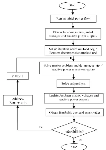
well-known Benders decomposition technique is applied in this paper. Accordingly, the resulted MINLP optimization problem is handled by decomposing the problem into two levels. The first level (master problem) is a mixed-integer linear problem and the second one is a nonlinear subproblem. Figure 5 illustrates the proposed procedure including the steps. In the beginning, initial power flow is accomplished to find initial voltages and reactive power output accompanied by the initial values of the Jacobian matrix. Now, the iterative Benders decomposition method begins. The master problem minimizes total expected payment function, operating regions of energy providers and reactive power outputs, while the sub-problem solves an AC power flow and checks the feasibility of master problem. So, required updated parameters are added to the master problem. The mathematical formulation of master and slave problems are presented below. Further details of Benders decomposition method are given in [19].
1) Master problem formulation: To decompose the optimization problem into a mixed-integer linear programming (MILP) master problem and non-linear programming (NLP) subproblem, some changes should be made. To do this, the objective function is changed to offer minimization instead of payment minimization. So, the uniform prices are determined after market clearing. Moreover, the quadratic opportunity cost component is approximated by a linear one. Hence, these modifications remove nonlinearity of the objective function, and it can be rewritten as in (28).
(
)
0, 0, 1, 1, 2, 2, 2, 3, ,
1
*
3, 3, 3, , 0 0, 1, 1, 2, 2,
1
. . . . .
1
. . . . .
2 G
g g g g g g g g A g
g
D
g g g A g d d d d d
d
Z m W m Q m Q m W Q
m Q W Q m W m Q m Q
=
=
= − + +
+ − + − + +
(28)The first sum of the objective function represents the linearized total EPF of generators. The second sum is the total EPF of DSOs. The last term (*) denotes the feasibility cost of each hourly subproblem, and it is determined by the Benders cuts constraint formulated as:
(
)
(
)
(
)
(
)
(
)
* 1 1 1
1, 1, 1, 2, 2, 2, 1
1 1 1
3, 3, 3, 1, 1, 1, 2, 2, 2,
1
G
m m m
g g g g g g
g D
m m m
g g g d d d d d d
d
W W W W
W W W W W W
− − −
=
− − −
=
+ − + − +
− + − + −
(29)where m−1 is the subproblem cost at iteration m-1, and
the remaining terms are Benders linear optimality cuts which couple master and subproblem to each other. The cuts are updated at each iteration as depicted in Figure 5. In addition to the constraint (29), the master problem is subjected to constraints (13)-(21), (30) and (32)-(34) (which are described in the following).
According to the problem formulations, load flow equations (6) and (7) form a system of nonlinear equations. Since the active power has been optimally determined through energy market; thus, at this stage, real power generation at each bus is constant except at the slack bus. Assuming that the bus voltage angles remain constant at each iteration of optimization, generator reactive power outputs can be considered as a function of voltage changes. The correlations between these variables can be given by a modified Jacobian matrix:
Q H V
= (30)
where
H
is modified Jacobian matrix which gives the relation between voltage correction (V ) and reactive power injection mismatch (Q) vectors. Notice that in (30), the elements ofH
are the partial derivatives ofi
Qwith respect to Vj in a linearized model of the power system. Using the above assumption and load flow equations, we will have:
(
)
( )
(
)
sin
2 sin - sin
i
ij i ij ij i j
j
i
ii i ii ii j ij ij i j
j i i
Q
h V Y j i
V
Q
h V Y V Y
V
= = − − +
= = − − +
(31)
where hij is the ijth element of matrix
H
calculated aftersolving subproblem. Each element of the matrix Q is either the generator’s reactive power mismatch (Qg) or
DER’s reactive power mismatch (Qd) which are formulated as below.
Q H V
= (32)
where Q1,g,Q2,g and Q3,g are generator’s reactive power at each operational region obtained from subproblem at the previous iteration; Q1,dand Q2,d are DER’s reactive power at each operational region obtained from subproblem at previous iteration. In addition to constraints (30) and (32), the variation range of V
and Q should be within their limits. Accordingly, the constraints (33) and (34) are added to the master problem.
, i
min max
i i i
V V + V V i (33)
step
Q Q
(34)
2) Subproblem formulation: The feasibility of the master problem’s solution is checked through subproblem employing an AC power flow. Then, any violations can be relieved by adjusting the generators’ reactive power output. The objective function presented in (35) minimizes the cost of deviations from the master problem solution (W1,g,W2,g,W3,g,W1,d, W2,d,Q1,g,Q2,g,Q3,g,Q1,d and Q2,dwhich are fixed by the master problem):
(
)
(
)
1 1
Min
G D
up dn up dn
g g d d
g d
Q Q Q Q
= =
+ + +
(35)where Qgup,Qgdn,Qdup and Qddn are slack variables of the optimization problem which are added to load flow equations to make the subproblem always feasible. The sub-problem objective function is subjected to constraints (8)-(12) and the following constraints:
1, 1, 2, 2, 3, 3,
g
up dn
g g g g g g g g
G W Q
Q = +W Q +W Q +Q −Q (36)
1, 1, + 2, 2,
d
up dn
d d
DERs W Q W d d Qd d
Q = Q + −Q (37)
min,g Gg B g,
Q Q Q (38)
max
2 d 1
min
d DG d
Q Q Q (39)
1 1 1
1, 1, 1, 2, 2, 2, 3, 3, 3,
1 1
1, 1, 1, 2, 2, 2,
; ;
;
m m m m m m
g g g g g g g g g
m m m m
d d d d d d
W W W W W W
W W W W
− − −
− −
= = =
= = (40)
Constraint (40) provides the marginal data (
gm−1 and1
m d
− ) of the master problem solution (and
g d
W W ) at the
same iteration. The marginal data are employed in the Benders cuts formulation as given in (29). The subproblem cuts are updated in each iteration to improve new master problem solution and this iterative procedure continues until the master problem solution is feasible.
4. CASE STUDY
In this section, several case studies are accomplished to demonstrate the validity and effectiveness of the proposed model. First, the ability of DERs’ reactive power provision is examined using the well-known 33-bus radial distribution network [20]. Then, the impact of DERs reactive power support on the development of a fair and competitive reactive power market is studied on the CIGRE 32-bus test system [21].
4. 1. DERs Reactive Power Support on 33-Bus Radial Distribution Network The 33-bus
Figure 5. Flowchart of the solution method
distribution network, as well as DERs’ buses, are depicted in Figure 6. It is worth noting that only network limitations are enforced, and DERs constraints are neglected in this study to further illustrate DERs impact on network’s reactive power support. According to the proposed method, the main substation’s reactive power injection is decreased, and DERs compensate the reactive power shortage to keep their connecting bus voltage until a violation occurred. The 𝑄𝐸𝑅𝐶 and main
Figure 6. 33-bus radial distribution network
Figure 7. Equaivalent reactive compensation of DERs
Figure 8. Main substation’s voltage for each scenario
Figure 9.QLI index for different scenarios
4. 2. Establishing a Reactive Power Market in the CIGRE 32-bus Network with the Presence of DERs
The CIGRE 32-bus test system is shown in Figure 10 [21]. This case contains 20 generator buses and 12 load buses, and 9 LV-side load buses connected to tap- changer transformers. Based on the system electrical distance, it is separated into three voltage control areas
(zone A, zone B, and zone C) [5]. Generators’ price offers are based on the data presented in [22]. It is assumed that all load buses can provide reactive power service. DERs penetration level at each load buses is considered up to 20% of its apparent power demand (i.e.
0.2√𝑃𝑙,𝑖2 + 𝑄𝑙,𝑖2) where Pl,i and Ql,i are respectively the
active and reactive demand at bus i). DSOs’ price offers are assumed to be identical for all the DSOs (i.e. 𝑚0,𝑑 = 1.5 and 𝑚1,𝑑= 𝑚2,𝑑= 2). In [2], buses 4072 in zone A,
2032 in zone B and 1042 in zone C are recognized as market power buses. These generators can significantly hike market prices. Therefore, the reactive power market settlement under the gaming of these market power holder with and without the presence of DERs is examined in the following.
To show the impact of DERs on the effectiveness of reactive power market, five scenarios are studies. At first, the market has been clear without DERs participation (named as the base case). Then, it is assumed that the possible reactive market power holders (i.e. buses 4072, 2032 and 1042) one by one increase their price offers up to ten times. Finally, it is assumed that all of the gaming generators raise their price offers up to ten times, simultaneously. Figure 11 compares total payment in reactive power market for the five market power scenarios. As it is evident, DERs participation in reactive power market considerably reduce the total market payment, and improve market efficiency. Note that the non-acceptance of DERs in the base case is due to the consideration of the high bid price of DERs. Selecting high prices for DERs would better illustrate the impact of DERs in market power
Figure 11.Total payment in reactive power market for market power scenarios
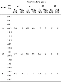
mitigation. Also, the market-clearing results for the last scenario that all the gaming generators exercise their potential market power are presented in Table 1. As it can be seen, DERs participation in the reactive market leads to 59.4% reduction in total payment and at least 165% reduction in areas’ uniform prices. Therefore, DERs successfully address the market power, and ISO can easily take advantage of these new resources to effectively handle reactive market issues. Also, total system losses of HV transmission system are reduced, when DERs participate in the reactive market.
TABLE 1. Market clearing results for gaming of 3 generators
Areas Bus No.
Area’s uniform prices
𝝆𝟎 𝝆𝟏 𝝆𝟐𝒂 𝝆𝟑𝒂
No DER
With DER
No DER
With DER
No DER
With DER
No DER
With DER
A 4072
5.8 1.5 0.88 0.88 5.7 2 0 0 4071
4011 4012 1013 1212 1014
B 4021
8.7 1.5 0.91 0.91 8.6 2 0 0 4042
4041 2032 1022 1021
C 4062
5.8 1.5 0 0 5.3 2 0 0 4063
4051 4047
1043 1042
Total payment ($) With DER 1609.5 Without DER 3972.4
Total losses (p.u) With DER 4.162 Without DER 4.24 Winner DSOs 4072, 2032, 1042, 1041, 51, 63
5. CONCLUSION
A new procedure for reactive power provision from DERs is presented in this paper. To do so, an algorithm is proposed to determine the equivalent reactive compensation of DERs from the distribution network to the main substation. This method guarantees the network limitation and DERs generation capability constraints. Then, a reactive power market settlement is proposed to effectively model the aggregated DERs reactive compensation at the transmission level. To cope with the complexity of the model, a Benders decomposition is applied. Simulation results show that local compensation of reactive power by a set of DERs would successfully support the system reactive demand. Also, the participation of DERs in reactive power market substantially mitigate market power exercise by gaming generators, reduce total payments, and provide new revenue for DERs.
6. REFERENCES
1. Zhong, J. and Bhattacharya, K., "Reactive power management in deregulated electricity markets-a review", in 2002 IEEE Power Engineering Society Winter Meeting. Conference Proceedings (Cat. No. 02CH37309), IEEE. Vol. 2, (2002), 1287-1292. 2. Feng, D., Zhong, J. and Gan, D., "Reactive market power
analysis using must-run indices", IEEE Transactions on Power Systems, Vol. 23, No. 2, (2008), 755-765.
3. Zhong, J. and Bhattacharya, K., "Toward a competitive market for reactive power", IEEE Transactions on Power Systems, Vol. 17, No. 4, (2002), 1206-1215.
4. Amjady, N., Rabiee, A. and Shayanfar, H., "Pay-as-bid based reactive power market", Energy Conversion and Management, Vol. 51, No. 2, (2010), 376-381.
5. Zhong, J., Nobile, E., Bose, A. and Bhattacharya, K., "Localized reactive power markets using the concept of voltage control areas", IEEE Transactions on Power Systems, Vol. 19, No. 3, (2004), 1555-1561.
6. Hao, S. and Papalexopoulos, A., "Reactive power pricing and management", IEEE Transactions on Power Systems, Vol. 12, No. 1, (1997), 95-104.
8. Petinrin, J. and Shaabanb, M., "Impact of renewable generation on voltage control in distribution systems", Renewable and Sustainable Energy Reviews, Vol. 65, (2016), 770-783. 9. Bai, L., Jiang, T., Li, F., Chen, H. and Li, X., "Distributed
energy storage planning in soft open point based active distribution networks incorporating network reconfiguration and dg reactive power capability", Applied Energy, Vol. 210, (2018), 1082-1091.
10. Madureira, A. and Lopes, J.P., "Ancillary services market framework for voltage control in distribution networks with microgrids", Electric Power Systems Research, Vol. 86, (2012), 1-7.
11. Calderaro, V., Galdi, V., Lamberti, F. and Piccolo, A., "A smart strategy for voltage control ancillary service in distribution networks", IEEE Transactions on Power Systems, Vol. 30, No. 1, (2014), 494-502.
12. Rueda-Medina, A.C. and Padilha-Feltrin, A., "Distributed generators as providers of reactive power support—a market approach", IEEE Transactions on Power Systems, Vol. 28, No. 1, (2012), 490-502.
13. Samimi, A., Kazemi, A. and Siano, P., "Economic-environmental active and reactive power scheduling of modern distribution systems in presence of wind generations: A distribution market-based approach", Energy Conversion and Management, Vol. 106, (2015), 495-509.
14. Samimi, A., Nikzad, M. and Siano, P., "Scenario-based stochastic framework for coupled active and reactive power market in smart distribution systems with demand response programs", Renewable Energy, Vol. 109, (2017), 22-40.
15. Doostizadeh, M., Khanabadi, M. and Ettehadi, M., "Reactive power provision from distributed energy resources in market environment", in Electrical Engineering (ICEE), Iranian Conference on, IEEE., (2018), 1362-1367.
16. Albarracin, R. and Alonso, M., "Photovoltaic reactive power limits", in 2013 12th International Conference on Environment and Electrical Engineering, IEEE., (2013), 13-18.
17. Ettehadi, M., Ghasemi, H. and Vaez-Zadeh, S., "Voltage stability-based dg placement in distribution networks", IEEE Transactions on Power Delivery, Vol. 28, No. 1, (2012), 171-178.
18. Khanabadi, M., Ghasemi, H. and Doostizadeh, M., "Optimal transmission switching considering voltage security and n-1 contingency analysis", IEEE Transactions on Power Systems, Vol. 28, No. 1, (2012), 542-550.
19. Conejo, A.J., Castillo, E., Minguez, R. and Garcia-Bertrand, R., "Decomposition techniques in mathematical programming: Engineering and science applications, Springer Science & Business Media, (2006).
20. Baran, M.E. and Wu, F.F., "Network reconfiguration in distribution systems for loss reduction and load balancing",
IEEE Transactions on Power Delivery, Vol. 4, No. 2, (1989), 1401-1407.
21. Walve, K., "’nordic32a–a cigre test system for simulation of transient stability and long term dynamics", Svenska Kraftnät, Vol., No., (1993).
22. El-Samahy, I., Bhattacharya, K., Cañizares, C., Anjos, M.F. and Pan, J., "A procurement market model for reactive power services considering system security", IEEE Transactions on Power Systems, Vol. 23, No. 1, (2008), 137-149.
A New Procedure for Reactive Power Market Clearing Considering Distributed
Energy Resources
M. Doostizadeha, M. Ettehadib
a Faculty of Engineering, Lorestan University, Lorestan, Iran
b Faculty of Engineering, University of Torbat Heydarieh, Torbat Heydarieh, Iran
P A P E R I N F O
Paper history:
Received 25 October 2018
Received in revised form 05 May 2019 Accepted 05 July 2019
Keywords:
Benders Decomposition Distributed Energy Resources Power System Operation Reactive Power Procurement
هدیکچ
دننام یبناج تامدخ هئارا یارب یهاگورین یاهدحاو ،یتنس روط هب متسیس رد ناخرچ هریخذ و ویتکار ناوت ندرک مهآرف
یاه
( هدنکارپ یژرنا عبانم هدرتسگ ذوفن روضح رد دوجو نیا اب .دنوش یم هتفرگ راکب تردق
DERs
و ) یدنمناوت عونتم یاه
عبانم نیا یم رظن هب یقطنم یرما ویتکار ناوت ناگدنهد هئارا ناونعب اهنآ یریگراکب ، ا رد ،ساسا نیا رب .دسر
کی هلاقم نی
تکراشم یارب دیدج شور
DERs
یم یفرعم ویتکار ناوت رازاب رد هبساحم تهج متیروگلا کی ادتبا روظنم نیدب .دوش
طسوت لیوحت لباق ویتکار ناوت هنیهب
DERs
هکبش قیرط زا متسیس هب عیزوت یاه
یم داهنشیپ لاقتنا یاه کی ،سپس .دوش
راشم زا یشان ویتکار ناوت دیرخ تهج لدم تک
DERs
یم یفرعم ویتکار ناوت رازاب رد یدروم تاعلاطم ،تیاهن رد .دوش
هنومن هکبش یور رب یعونتم عیزوت ی
33 لاقتنا هنومن هکبش و هساب 32
و یشخبرثا نداد ناشن یارب هرگیس هساب
.تسا هدش ماجنا یداهنشیپ لدم یجنسرابتعا
![Figure 1. Reactive capability curves: (a) SG, (b) DFIG [12]](https://thumb-us.123doks.com/thumbv2/123dok_us/17659.2001801/3.595.337.515.598.732/figure-reactive-capability-curves-a-sg-b-dfig.webp)
![Figure 4. Reactive power offer components of a synchronous generator [4]](https://thumb-us.123doks.com/thumbv2/123dok_us/17659.2001801/4.595.328.521.627.723/figure-reactive-power-offer-components-synchronous-generator.webp)