Please cite this article as: M. A. K. Benalouach, A. Sahli, S. Sahli, Flow Seals Parameters Analysis For Rotors, International Journal of Engineering (IJE), IJE TRANSACTIONS A: Basics Vol. 32, No. 1, (January 2019) 177-183
International Journal of Engineering
J o u r n a l H o m e p a g e : w w w . i j e . i rFlow Seals Parameters Analysis For Rotors
M. A. K. Benalouach*a, A. Sahlia,b, S. Sahlic
a Laboratoire de recherche des technologies industrielles, Université Ibn Khaldoun de Tiaret, Département de Génie Mécanique, Route de Zaroura, Tiaret, Algérie
b Laboratoire de Mécanique Appliquée, Université des Sciences et de la Technologie d’Oran (USTO MB), Oran El Menouar, Algérie c Université d’Oran 2 Mohamed ben Ahmed, Oran, Algérie
P A P E R I N F O
Paper history:
Received 31 May 2017
Received in revised form 21 April 2018 Accepted 28 April 2018
Keywords: Fluid Seals Finite Volume Method Rotating Machinery Dynamic Coefficients
A B S T R A C T
The interaction of work fluid mechanics with that of the rotary system itself, basically composed of axes, bearings and rotors, is performed by inserting equivalent dynamic coefficients in the mathematical model of the rotor, the latter being obtained by the finite element method. In this paper, the dynamic coefficients of inertia, stiffness and damping of the flat seals analyzed here are evaluated, from the point of view of the dependence of the geometric characteristics of the seals and the operating conditions of the machine. Then, once incorporated into the entire rotating system model, the flow seals are also analyzed from the point of view of their influence on the overall dynamic response of the rotating machine. The mechanical seals of the cylindrical, conical and stepped type were analyzed, determining, for this purpose, the dynamic coefficients of damping, stiffness and inertia. In addition, the influence of physical and operational parameters of the system in relation to these elements were verified. Therefore, the modeling and analysis of flow seals are inserted in an interesting and promising way in the context of the global research theme in rotary machines.
doi: 10.5829/ije.2019.32.01a.23
1. INTRODUCTION1
The origin of the analysis of flow seals goes back to the study of rotary machines and, above all, to the development of the theory of lubrication initially applied to the bearings. For, from the equation of this theory, there was the expansion of knowledge and application to mechanical seals.
Lee and Polycarpou [1] Waara et al. [2] pioneered the study of hydrodynamic lubrication. Although they did not know each other, the experimental results obtained, regarding the support of a rotor by an oil film, were similar.
The relative motion between two surfaces separated by a fluid film analyses were successfully addressed in the scope of deterministic field [3-8].
In the context of annular plane seals, Ha et al. [9], from the analysis of eccentric annular plane seals,
*Corresponding Author Email: [email protected](M. A. K. Benalouach)
performed a study for floating ring seals, in order to determine the floating position of the ring, the coefficients dynamics of the rotor and the design parameters, with the solution based on Nelson and Nguyen Fourier Transform method [10]. Kwanka [11] reported that the destabilizing force present on the seals is caused by the cross-stiffness terms, and these are counterbalanced by the direct damping terms, so it is necessary to know and take into account the damping in the seals [12].
based on the magnetic fluid seal with multiple magnetic sources or stepped labyrinth seals to improve the pressure capacity of the magnetic fluid seal with a large sealing gap.
Shen et al. [18] simulated a system composed of rotor, bearing, foundation and labyrinth seal. The governing equations were described by the finite element method. After the theoretical analysis, experimental tests were performed. The theoretical results were in agreement with those obtained experimentally [19, 20]. The method of analysis in this work was based on theory discussed by Childs [21].
In this paper, the mechanical seals of the cylindrical, conical and stepped type were analyzed, determining, for this purpose, the dynamic coefficients of damping, stiffness and inertia. In addition, the influence of physical and operational parameters of the system in relation to these elements were verified. Therefore, the modeling and analysis of flow seals are inserted in an interesting and promising way in the context of the global research theme in rotary machines; because, it would be possible to insert the effects of this component in the complete mathematical model of the rotating system in the computational package, until then developed for axes, rotors, bearings and structures.
2. GOVERNING EQUATIONS
The governing equations for fluid analysis, mass conservation equation and the amount of movement, axial and circumferential, are obtained through a basic equation, in integral form, presented by Fox and McDonald [22], represented by Equation (1).
. . .
c v c s system
dN d
d V d A
dt dt
(1)wehere N is extensive arbitrary property; is intensive property corresponding to N, or extensive property per unit mass; c.v. is control volume; c.s. is control surface; ρ is specific mass [kg /m3];
V is velocity measured relative to the surface of the control volume [m/s]; d
is volume differential [m3]; d A is Area differential [m2];
system
dN dt
is Total rate of change of the extensive
property, N;
.
c v
d d
dt
is rate of change of the
extensive property, N with time and existing in the control volume.
d
: Mass element in control volume [kg];
.
c v d
: Total amount of the extensive property, N, existing in the control volume;. .
c sV d A
: Net flow rate in the extensive property, N, through the surface of control;.
V d A
: Flow rate through the area element. The sign of this term depends on the of the velocity vector,V , relative to the area vector.
According to Moran and Shapiro [23], a control volume, also known as an open system, is a region of space enveloped in a prescribed contour, where the mass flows can cross its border. A closed system, or control mass, is characterized by a certain amount of mass under study and always contains the same amount of matter, that is, its portion is fixed. The boundary of the system, in turn, is called the control surface.
An intensive property is a quantity dependent only on the state of the system and not on its mass, such as temperature, pressure and specific mass, while extensive property depends directly on the mass of the system, such as volume and mass.
Thus, general Equation (1) represents a generic ratio of the rate of change of any extensive property of a system and its variation in a control volume, so it is necessary that the control volume and the system coincide at the instant of time analyzed. The control volume was adopted for the analysis of Equation (1), since, because it is a fluid, it becomes difficult to identify and follow its mass at different instants of time, since it may be deforming
Thus, it is possible to obtain the conservation equations of mass and quantity of movement, and, following formulation in the integral form, similar to Equation (1). It can be developed in the differential form, presenting them in the most appropriate way to the configurations of this study, according to Childs [21]. From Equation (1) the formulations describe, respectively, the continuity, axial motion and circumferential motion equations are:
1
0
HU HW
H
t R Z
(2)
r s
HZ HZ
P H
Z
W U W W
H W
t R Z
(3)
r s
H H
H P
R
U U U U
H W
t R Z
(4)
where, W is the axial velocity component and U is the circumferential or tangential velocity component, measured through the film. 'r' and 's', respectively; characterize the rotor and stator faces, as well as τr and τs are the shear stresses acting at the rotating fluid interface and at the static interface, H represents the gap function at the flow.
The shear stressesHZr , s HZ , rH,
s H
fluid (r) and the static interface (s). From the definitions [21], these stresses are characterized by the stator and rotor friction factors (s, r), and by the relative velocities of mass flow at the stator and rotor interfaces. Because of these stresses, the governing equations for fluids cannot be simplified in the Reynolds equation, unlike in lubricated bearings.
The dimensionlessness of the conservation equations of mass and quantity of axial and circumferential motion, is necessary to make them independent of the direct parameters of the system, ie, diameter, gap and seal length, thus avoiding eventual variations of the equations in function of these parameters.
In addition, the use of the dimensionless formulation facilitates the application of the numerical method employed, since it is possible to transform the real mesh into a uniform numerical mesh. Starting from the definitions:
H Slack function along Z [m],
C0 Seal clearance relative to the input shaft (Z = 0) [m], C1 Seal clearance relative to the output shaft (Z = L) [m],
r
C Radial Average clearance [m],
Q Volumetric flow rate [m3/s], L Axial length of seal [m],
R Spindle radius [m],
U Mean circumferential velocity [m/s], W Mean axial velocity [m/s],
Rotation speed of the rotor [rad/s], P Pressure [N/m2],
0 / 2 r
W Q RC W0 is the mean axial velocity [m/s], T Flow time of the fluid along the axis [s]. According to Childs [21], the dimensionless variables are given by the following relations:
z = Z/L Non-dimensional variable of length,
= t/T Non-dimensional variable of time, T = L/W0 Flow time of the fluid along the axis [s], p = P/ρW0 Non-dimensioned pressure variable,
u = U/R Dimensional variable of circumferential velocity,
h = H/ Cr Addimensionalized clearance variable, w = W/W0 Dimensional axial velocity variable, B * R/W0 Parameter dimensionless.
In the dimensionless form the equations of the conservation of mass, amount of axial movement and amount of movement are:
0 hu hw h L b R z (5)
2 2
s s r r
r r
p w L w L
h u u
z C C
w L w w
h b u u
R z (6)
1
2 2
s s r r
r r
u
h L p u L L
u u
b R C C
u L u u
h b u w
R z (7)
Likewise, we have the dimensionlessness of the relative velocities, (Equations (8) and (9)), and the friction factors related to the Moody model (Equations (10) and (11)), which are necessary parameters for the solution of Equations (5) to (7).
1/ 2
2 2 2
1/ 2 2 2 2 1/3 3 2 1 1/3 3 2 1 1 1 1 s r s s s r r r
u w b u
u w b u
a a a h hu a a a h hu (8) (9) (10) (11) Being that: 3 4 1 2 4 6 2 3 0 0 0 Re 1,375.10 2.10
2.10 10 Re
2 / / r r s r s
Coefficients for the solution by Mood
a a
a
y
C W Reynolds num er
a b
es Stator Absolute Roughness [m] er Absolute rotor rigidity [m]
Absolute viscosity [Pa.s]
/ 2
s s
r
e C
Stator Relative Roughness
/ 2
r r
r
e C
Relative Rotor Roughness
Thus, from the dimensionless form of the equations of continuity, the amount of axial and circumferential motion, Equations (9), (10) and (11), respectively; it is possible to apply the finite volume method using a uniform and constant mesh.
The great advantage of dimensionlessness is that this mesh is independent of the physical and operational parameters of the system, that is, for any type of seal and any operating condition, the system is solved with the same mesh. Once the numerical simulation is finished, the dimensionless results can then be converted into its dimensional form to analyze the influence of the design variables of the flow seals.
3. RESULTS AND DISCUSSION
3. 1. Conical Flat Seals The analysis of the conical seals was performed for the seal considering, for this, different radial clearances in the entrance and the exit. The other geometric and operational data used are similar to those for cylindrical flat seals; data are presented in Table 1.
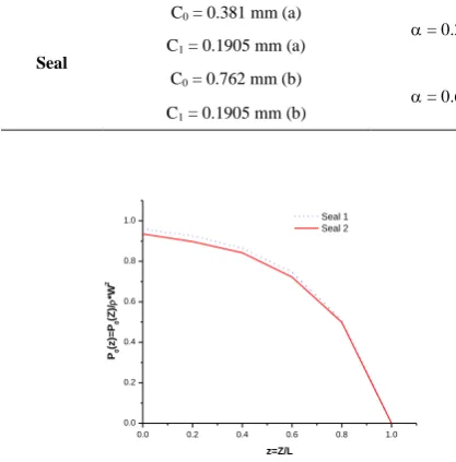
The values of the radial clearance used are shown in Table 2, as well as the slope angle values, α, for the seal. It is important to analyze this parameter, since the theory applied in this work is only valid for very small angles. Thus, according to Table 2, the applicability of the theory is verified, since α is always smaller than one degree.
Figure 1 describes the pressure distribution along the seal length for the seal described in Tables 1 and 2.
As shown in Figure 1, it can be seen that the pressure distribution presents a very stable variation in relation to increase in radial clearance when the C0/C1 ratio is maintained.
Table 3 presents the values of the dynamic coefficients for the two seals analyzed in Figure 1.
Similarly, qn increase in radial clearance results in a decrease in the value of the dynamic coefficients.
TABLE 1. Tapered flow seal parameters for disturbed system
calculations [21]
P (bars) R(mm) L(mm) (rpm)
35 76.20 50.80 3000
µ (PaS) (Kg/m3) e s = r
1.3 10-3 1000 0.1 1.0 0.001
TABLE 2. (a) and (b) input values radial clearances (C0) and
output (C1) for conical seal
Seal
C0 = 0.381 mm (a)
= 0.22° C1 = 0.1905 mm (a)
C0 = 0.762 mm (b)
= 0.65° C1 = 0.1905 mm (b)
0.0 0.2 0.4 0.6 0.8 1.0
0.0 0.2 0.4 0.6 0.8 1.0
P0
(z
)=
P0
(Z
)/
*W
2
z=Z/L
Seal 1 Seal 2
Figure 1. Pressure distribution, p0(z) for two types of tapered
seals
TABLE 3. Staggered flow seal parameters for calculations
with the disturbed system.
P (bars) R(mm) L(mm) (rpm) µ (PaS)
35 76.20 25.40 3000 1.3 10-3
(Kg/m3) e s = r
1000 0.1 1.0 0.001
According to Childs and Dressman [24], the introduction of an angle in the original cylindrical seal, resulting in a conical seal, causes a reduction in the direct damping term and an increase in the inertia term, but the direct stiffness term continues practically constant.
Comparing the values for the seal, it can be seen that the inertia term is the one that presents the greatest variation, in the order of 40%, since the direct damping term suffers a reduction of 4% while the direct term of stiffness shows a decrease in the order of 3.5%.
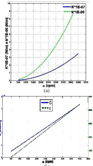
Figure 2 show the behavior of the direct terms of stiffness and damping and the cross-stiffness term for the seal type, shown in Table 2, in relation to the pressure gradient. The other coefficients are not shown in the graph because they remain practically constant. The same tendency observed for the coefficients in the cylindrical seal is present in the conical seal, the values of the dynamic coefficients are smaller. Figure 3 describe the behavior of the dynamic coefficients as a function of the rotation speed of the shaft. Again, the inertia term was not represented by being constant with respect to the speed of rotation.
As shown Figure 2, the dynamic coefficients follow the same behavior of the cylindrical seals as a function of the speed of rotation, as shown in Figure 3. Likewise, the radial clearance interferes with the values of the coefficients, decreasing them as the ratio radial clearance and radius of the axis increases.
3. 2. Staggered Flat Seals The same analysis performed for tapered seals was performed for staggered seals. Thus, the type of seal is considered and their specifications are described in Tables 3 and 4.
Figure 2. Direct coefficients of stiffness, damping and
(a)
(b)
Figure 3. (a) Direct coefficients and cross-stiffness versus
ω,(b) Direct coefficients and cross-damping versus ω. seal
TABLE 4. Radial clearances values of input (C0) and output
(C1) for staggered seals
Seal C01 = C11 = 0.381 mm C02 = C12 = 0.1905 mm
Similar to the cases studied previously, it is verified that the increase of the radial clearance in the stepped flow seal increases the amount of pressure absorbed at the entrance of the seal. Since the stepped seal consists of two sections of cylindrical seals, this same effect appears at the junction point of the seal sections. Some differences are found by analyzing the coefficients in Table 5 and the dynamic coefficients for cylindrical and conical seals.
In the case of staggered seals, with the increase of radial clearance, the direct and cross-stiffness and direct damping terms decrease, while the terms of inertia and crossover damping increase. This is due to the effect of the second cylindrical section of the stepped seal. Therefore, in this case, the circumferential velocity has an initial condition other than zero, which results from the value coming from the first section. In addition, another abrupt load loss occurs, which raises the direct term of rigidity in relation to the seals analyzed.
Figure 4 show the influence of the pressure drop on the dynamic coefficients for each of the seals described in Tables 4 and 5.
The profile of the distribution of the coefficients represented in Figure 5 is similar to cylindrical and staggered seals; however, with the increase of radial clearance the direct damping and cross-stiffness terms do not vary significantly, since the direct stiffness term decreased by 48%.
TABLE 5. Calculated values of the dynamic coefficients
Seal
K [x107 N/m] 2.685
k [x107 N/m] 0.455
C [x105 N.s/m] 0.256
c [x105 N.s/m] 0.4107
M [kg] 14.125
Figure 4. Direct coefficients of stiffness, direct damping and
stiffness cross versus ΔP for seal
(a)
(b)
Figure 5. (a) Direct coefficients and cross stiffness versus
It is verified, in this case, that the direct damping coefficients and cross-stiffness vary little when modified radial clearance, while the direct term of stiffness shows a considerable drop. As already mentioned, due to the new conditions for the stepped seal analysis, the value of the crossover coefficient of damping increases with an increase in the radial clearance, but still presents the same linear behavior in relation to the variation of the speed of rotation.
4. CONCLUSION
The flow seals present a turbulent behavior, due to the radial clearance, relatively higher between the seal and the shaft when compared to that of the lubricated bearings, the high axial velocity and the loss of load that crosses them, and therefore cannot be studied from the Reynolds theory. Thus, the governing equations for fluids are necessary for the analysis of the characteristics of the fluid along the seal.
A bibliographic review was carried out to understand the physical concepts involved in the analyzed system, as well as to verify the evolution in studies of flow seals over the years.
From the analysis considering the centered axis, it was possible to verify that the geometric characteristics of the mechanical seals exert great influence on the distributions of pressure and circumferential velocity.
The study of the perturbed system allowed determining the coefficients, direct and crossing, of stiffness and damping, besides the terms of inertia. From these coefficients, the mechanical seals could be integrated in the numerical analysis of a rotating system.
It was verified that the variation of geometric and operational parameters, such as ratio between radial clearance, between the seal and the shaft, and the radius of the axis (Cr/R), ratio of seal length to shaft diameter (L/D), relative roughness (εs), loss coefficient at the entrance of the seal (ξ), recovery coefficient at the exit of the seal (ξe), pressure gradient (ΔP) and rotational speed of the (ω) axis can significantly change the dynamic coefficients of the flat cylindrical flow seals, and consequently can affect the resonance condition of the rotating system. It is important to note that the most critical case occurs when the L/D ratio becomes very large, since the inertia term reaches very high values and the direct term of rigidity becomes smaller and smaller, becoming negative in the presented case.
The analysis of the conical seals allows to observe that the relation between the pressure variation and the dynamic coefficients is not linear, since increasing the gap of this type of seal, but maintaining Cr/R ratio, the pressure distribution remains practically constant, while the dynamic coefficients showed a remarkable 40% variation for the direct stiffness terms, 50% for the
crossover terms of stiffness and direct damping, and 52% for the crossover terms of damping and inertia. In addition, it can be seen that the three types of seals analyzed have similar behavior when changing parameters such as pressure drop and the rotation speed of the shaft.
The results obtained for cylindrical flat seals are in agreement with those found in the literature, highlighting that all graphs presented were calculated by Moody's friction factor, the same used in the reference literature.
It was verified that the application of the finite volume method presents a satisfactory result in the analysis of mechanical seals, which is very promising for the future study of more complex flow stamps with geometry, such as the labyrinth seal and honeycomb.
The analyzes of the flat seals were added to the software, thus enabling a more complete study of the rotating system. It was noted that the presence of the flow seal alter the system, changing its natural frequency. Moreover, this element represents a further coupling point between the shaft and the foundation and, consequently, constitutes a further transfer element of the flexibility effect of the structure for the dynamic response of the rotor.
5. REFERENCES
1. Lee, C.-H. and Polycarpou, A.A., "Static friction experiments and verification of an improved elastic-plastic model including roughness effects", Journal of Tribology, Vol. 129, No. 4, (2007), 754-760.
2. Waara, P., Hannu, J., Norrby, T. and Byheden, Å., "Additive influence on wear and friction performance of environmentally adapted lubricants", Tribology International, Vol. 34, No. 8, (2001), 547-556.
3. Norton, J. and Arraez, C., "Machine design", São Paulo: Bookman, (2000).
4. Hamrock, B.J., Schmid, S.R. and Jacobson, B.O., "Fundamentals of fluid film lubrication, CRC press, (2004). 5. Hirano, T., Guo, Z. and Kirk, R.G., "Application of
computational fluid dynamics analysis for rotating machinery— part ii: Labyrinth seal analysis", Journal of Engineering for
Gas Turbines and Power, Vol. 127, No. 4, (2005), 820-826.
6. Ji, F., Wang, Y., Tian, J. and Zhang, Y., "Experimental modeling of a long orifice-type restrictor of high speed turbine hybrid bearing", International Journal of
Engineering-Transactions, Transactions C: Aspects, Vol. 29, No. 3 (2016):
378-385.
7. Sikarwar, B., Bhadauria, A. and Ranjan, P., "Towards an analytical model for film cooling prediction using integral turbulent boundary layer", International Journal of
Engineering-Transactions A: Basics, Vol. 29, No. 4, (2016),
554-562.
8. Teja, S.K., Karthikeyan, C. and Kumar, M.S., "Investigation of radiative cooling using a photonic composite material for water harvesting", International Journal of
9. Ha, T.-W., Lee, Y.-B. and Kim, C.-H., "Leakage and rotordynamic analysis of a high pressure floating ring seal in the turbo pump unit of a liquid rocket engine", Tribology
International, Vol. 35, No. 3, (2002), 153-161.
10. Childs, D.W. and Wade, J., "Rotordynamic-coefficient and leakage characteristics for hole-pattern-stator annular gas seals—measurements versus predictions", Journal of Tribology, Vol. 126, No. 2, (2004), 326-333.
11. Kwanka, K., "Dynamic coefficients of stepped labyrinth gas seals", in ASME International Gas Turbine and Aeroengine Congress and Exhibition, American Society of Mechanical Engineers, (1999).
12. Staubli, T. and Bissig, M., "Numerically calculated rotor dynamic coefficients of a pump rotor side space", in International Symposium on Stability Control of Rotating Machinery (ISCORMA), South Lake Tahoe, CA, August. (2001), 20-24.
13. Dereli, Y. and Eser, D., "Effects of shear stress forces to rotordynamic coefficients in staggered labyrinth seals",
Proceedings of the Institution of Mechanical Engineers, Part
A: Journal of Power and Energy, Vol. 220, No. 4, (2006),
387-394.
14. Pugachev, A.O. and Deckner, M., "Cfd prediction and test results of stiffness and damping coefficients for brush-labyrinth gas seals", in ASME Turbo Expo: Power for Land, Sea, and Air, American Society of Mechanical Engineers., (2010), 175-185. 15. Pugachev, A.O., Kleinhans, U. and Gaszner, M., "Prediction of
rotordynamic coefficients for short labyrinth gas seals using computational fluid dynamics", Journal of Engineering for Gas
Turbines and Power, Vol. 134, No. 6, (2012),
doi:10.1115/1.4005971.
16. Hasegawa, N., Yoshioka, H. and Shinno, H., "Noncontact gravity compensator with magnetic fluid seals", Journal of
Advanced Mechanical Design, Systems, and Manufacturing,
Vol. 10, No. 5, (2016), doi:10.1299/jamdsm.2016jamdsm0078. 17. Yang, X.L. and Li, D.C., "Experimental investigation of
diverging stepped magnetic fluid seals with large sealing gap",
International Journal of Applied Electromagnetics and
Mechanics, Vol. 50, No. 3, (2016), 407-415.
18. Shen, X., Jia, J., Zhao, M. and Jing, J., "Numerical and experimental analysis of the rotor—bearing—seal system",
Proceedings of the Institution of Mechanical Engineers, Part
C: Journal of Mechanical Engineering Science, Vol. 222, No.
8, (2008), 1435-1441.
19. Pennacchi, P., Bachschmid, N. and Tanzi, E., "Light and short arc rubs in rotating machines: Experimental tests and modelling", Mechanical Systems and Signal Processing, Vol. 23, No. 7, (2009), 2205-2227.
20. Cheng, M., Meng, G. and Jing, J., "Numerical and experimental study of a rotor–bearing–seal system", Mechanism and
Machine Theory, Vol. 42, No. 8, (2007), 1043-1057.
21. Childs, D. and Childs, D.W., "Turbomachinery rotordynamics: Phenomena, modeling, and analysis, John Wiley & Sons, (1993).
22. Fox, R.W. and McDonald, A.T., "Introduction to fluid mechanics, John Wiley&Sons", Inc., New York, (1994). 23. Moran, M., Shapiro, H., Boettner, D. and Bailey, M., Principles
of thermodynamics for engineering. 2008, Wiely, NY.
24. Childs, D.W. and Dressman, J.B., "Convergent-tapered annular seals: Analysis and testing for rotordynamic coefficients",
Journal of Tribology, Vol. 107, No. 3, (1985), 307-316.
Flow Seals Parameters Analysis For Rotors
M. A. K. Benalouacha, A. Sahlia,b, S. Sahlic
a Laboratoire de recherche des technologies industrielles, Université Ibn Khaldoun de Tiaret, Département de Génie Mécanique, Route de Zaroura, Tiaret, Algérie
b Laboratoire de Mécanique Appliquée, Université des Sciences et de la Technologie d’Oran (USTO MB), Oran El Menouar, Algérie c Université d’Oran 2 Mohamed ben Ahmed, Oran, Algérie
P A P E R I N F O
Paper history:
Received 31 May 2017
Received in revised form 21 April 2018 Accepted 28 April 2018
Keywords: Fluid Seals Finite Volume Method Rotating Machinery Dynamic Coefficients
هديكچ
ا هدش لیکشت اهروتور و اهناقاطای ،اهروحم زا اتدمع هک یشخرچ دوخ متسیس اب تلاایس کیناکم لماعت ب ،تس
داد رارق ا ن
رد .دوش یم لصاح دودحم ناملا شور طسوت هک ،دوش یم ماجنا روتور یضایر لدم رد لداعم ایوپ بیارض ا
قم نی ،هلا
ییایوپ بیرض د زا ،تسا هتفرگ رارق یبایزرا دروم اجنیا رد تخت موم و رهم هبساحم و یتخس ،یسرنیا
هاگدی یگتسباو
رارق یشخرچ متسیس لک لدم رد هک یماگنه ،سپس .هاگتسد یتایلمع طیارش و موم و رهم یسدنه تایصوصخ م
ریگ ی ،د
اگتسد یلک یکیمانید خساپ رب اهنآ ریثأت رظن زا زین نایرج موم و رهم رهم .دوش یم لیلحت یشخرچ ه
و موم ه یکیناکم یا
ایوپ بیارض روظنم نیا یارب و دنتفرگ رارق لیلحت و هیزجت دروم یا هلپ و یطورخم ،یا هناوتسا عون هم یی
و یتفس ،را
inertia
ع نیا اب طابترا رد متسیس یتایلمع و یمسج یاهرتماراپ ریثات ،نیا رب هولاع .دندش نییعت أت رصان
ب .دش دیی ،نیاربان
وضوم هنیمز رد هدننک راودیما و بلاج عوضوم کی رد ار موم و رهم نایرج لیلحت و هیزجت و یزاس لدم قحت ع
یناهج قی