© Shiraz University
IMPLEMENTATION OF SENSORLESS SPEED CONTROL FOR TWO-PHASE
INDUCTION MOTOR DRIVE USING ISFOC STRATEGY
*H. BEN AZZA
1**M. JEMLI
1, M. BOUSSAK
2AND
M. GOSSA
11Unité de recherche en commande, surveillance et sûreté de fonctionnement des systèmes (C3S) Equipe Développement des Systèmes Electrotechniques (DES)
Ecole Supérieure des Sciences et Techniques de Tunis (ESSTT) 5 Avenue Taha Hussein –BP 56, Bab Mnara 1008 Tunis – Tunisie
Email: [email protected]
2 Laboratoire des Sciences de l’Information et des Systèmes (LSIS) – UMR CNRS 6168 Centrale Marseille Recherche et Technologies (CMRT)
Ecole Centrale Marseille (ECM) – Technopôle Château Gombert –13451 – Marseille Cedex 20 – France
Abstract– This paper presents a new technique based on model reference adaptive system (MRAS) observer for sensorless speed control of Two-Phase Induction Motor (TPIM). The MRAS identification is performed by means of comparison of stator fluxes obtained from both stator and rotor equations with stator voltage and current measurements. Simulation and experimental results for a 1.1 kW TPIM set-up are presented and analysed using a dSpace system with a DS1104 controller board based on digital signal processor (DSP) TMS320F240. Simulation and experimental results at nominal, low and zero speeds confirm the effectiveness of the proposed sensorless speed controlled TPIM drive.
Keywords– Two-phase induction motor (TPIM), indirect stator-field-oriented control (ISFOC), model reference adaptive system (MRAS)
1. INTRODUCTION
Two-Phase Induction Motor (TPIM) is widely used in several industrial and domestic applications. In those applications the motor runs at constant frequency and is fed directly from the ac grid without any type of control strategy. The TPIM is found in air conditioners, washers, dryers, industrial machinery, fans, compressors, tools, blowers, vacuum cleaners, household appliances and many other applications. The reduction in the cost of the power electronic circuitry provides economically justifiable applications for adjustable speed Two-Phase Induction Motor Drives (TPIMD). In recent years, several methods that use inverters for the variable speed control of TPIM have been proposed [1]-[15]. An alternative approach is to use a 6 switch three phase Voltage-Source Inverter (VSI) bridge, connecting the two windings of the motor as an unbalanced load between the phases, as shown in Fig. 3. This is a more cost effective solution [1], [2], [9], [11], [16]. Recently, Stator Field Oriented Control (SFOC) of TPIMD has been gaining wide attention in literature [1]-[3]. In vector control, the flux linkage magnitude and the electromagnetic torque are controlled independently [14]-[15]. The SFOC represents a better solution to satisfy the industrial requirements. The field orientation is relatively straightforward in all operating conditions if the rotor speed is accurately known, which traditionally necessitates a sensor on the shaft of the motor. However, there are several reasons for preferring a system without the sensor. The cost of the speed sensor, at least for machines with ratings less than 10 kW, is in the same range as the cost of the motor itself. The
mounting of the sensor to the motor is also an obstacle in many applications. A Sensorless system where the speed is estimated instead of measured would essentially reduce the cost and complexity of the drive system. In the existing literature, some approaches have been suggested for speed Sensorless single-phase induction motor in [2], [3], [15], [17], [18], [19] and [20]. In papers [2] and [3], the authors proposed a method of rotor speed estimation based only on the measurement of the main and auxiliary windings stator currents and that of a reference q-axis current generated by the control algorithm. In [20], the authors suggested to estimate the motor speed using rotor voltage vector which is defined in complex domain. In this paper, for the first time, a speed estimation method is introduced for TPIMs based on the Model Reference Adaptive System (MRAS) to overcome the problems of system complexity and cost. The Sensorless speed control strategy using MRAS techniques is based on the comparison between the outputs of two estimators when motor currents and voltages must still be measured [21], [22]. In this paper we focus on a real implementation using DS1104 controller board of Indirect Stator Field Oriented Control (ISFOC) of a TPIM supplied by Proportional plus Integral (PI) current controlled inverter. Our contribution is real time implementation of a Sensorless speed control using the MRAS approach. Simulation and experimental results are presented to demonstrate the main characteristics of the proposed drive system. The Sensorless speed control algorithm is employed in this work and is implemented at rated, low, and zero speed operations
2. TWO-PHASE INDUCTION MOTOR MODEL
The set of equations that defines the dynamic model for TPIM in a stationary reference frame is given by:
dt d i R
v s
s sd
sα= α+ φα (1)
dt d i R
vsβ= sq sβ+ φsβ (2)
β α α+ φ +ωφ
= r r
r
ri ddt
R
0 (3)
α β
β −ωφ
φ +
= r r
r
r dt
d i R
0 (4)
α α
α = +
φs Lsdis Msrdir (5)
β β
β = +
φs Lsqis Msrqir (6)
α α
α = +
φr Lrir Msrdis (7)
β β
β= +
φr Lrir Msrqis (8)
) i i M i i M ( n
Te = p srqsβ rα− srd sαrβ (9)
It is seen that Eqs. (1) to (8) present the model of an asymmetrical TPIM due to the unequal resistances and inductances of the main and auxiliary windings. This asymmetry causes an oscillating term in the electromagnetic torque [1]. In order to simplify the mathematical model of a TPIM it is necessary, as a first step, to introduce a transformation matrix ⎥
⎦ ⎤ ⎢ ⎣ ⎡ =
k 0
0 1
1 αβ s αβ
s
Ti
i
=
(10)1
αβ
s 1
αβ
s T v
v = − (11)
1 s 1
sαβ=T−φαβ
φ (12)
where: srq srd M M k=
Using Eqs. (1) to (12), the new mathematical model of the TPIM in a stationary reference frame can be described by the following equations:
dt d i R
v s 1
1 s sd 1
sα α α
φ +
= (13)
1 s sd sq 2 1 s 1 s sd 1
s dt (k R R )i
d i R
v β = β + φβ + − β (14)
β α α+ φ +ωφ
= r r
r
r dt
d i R
0 (15)
α β
β −ωφ
φ +
= r r
r
r dt
d i R
0 (16)
α α
α = +
φs 1 Lsdis 1 Msrdir (17)
1 s sd sq 2 r srd 1 s sd 1
sβ =L iβ +M iβ+(k L −L )iβ
φ (18)
1 s srd r
r
rα =Liα+M iα
φ (19)
1 s srd r r
rβ =Liβ+M iβ
φ (20)
) i i i i ( M n
Te = p srd sβ1rα− sε1rβ (21)
3. INDIRECT STATOR FIELD ORIENTED CONTROL (ISFOC)
Using Eqs. (17), (18) and (21), electromagnetic torque as a function of stator fluxes and stator currents can be written as:
) T i i ( n
Te = p φsα1sβ1−φsβ1sα1+Δ (22)
where: ΔT=(k2Lsq−Lsd)isβ1isα1
In the same way, using Eqs. (15-20), we can determine the dynamic model that relates the stator flux to the stator currents:
s 1 2 q sq s1
sd d 1 s r sd 1 s 1 s 1
s k L i
dt di L i L 1 dt d β α α β α
α +σ +ω σ
τ = ωφ + φ τ + φ (23) 1 s sd d 1 s sq q 2 1 s r sq 2 1 s 1 s r 1
s L i
dt di L k i L k 1 dt d α β β α β
β + σ −ωσ
τ = ωφ − φ τ + φ (24) in which: r sd 2 srd
d =1−LML
σ ,
r sq
2 srq
q L L
M 1
σ = − ,
sd sd
sd =RL
τ , sq sq sq R L =
τ and
r r
r = RL
The vector model for the stator-flux control written for an arbitrary frame (denoted by the superscript a) using Eqs. (23) and (24) are given by:
a s a 1 s sd d a a 1 s sd d a 1 s r sd a 1 s a a 1 s r a 1
s j( ) L i
dt di L i L ) ( j 1 dt
d +σ + ω −ωσ +ς
τ = φ ω − ω + φ τ + φ (25)
where: ja
1 s 1 s a 1 s a 1 s a 1
s =φα +jφβ =(φα +jφβ )e−δ
φ j a 1 s 1 s a 1 s a 1 s a 1
s i ji (i ji )e
i = α + β = α + β −δ
(
)
s1 ja1 s r sd sq 2 a
s dt e
di j i 1 j L L
k β β −δ
⎥ ⎥ ⎦ ⎤ ⎢ ⎢ ⎣ ⎡ + ⎟⎟ ⎠ ⎞ ⎜⎜ ⎝ ⎛ τ + ω − = ς
We choose a reference frame linked to the stator flux, so that the d axis coincides with the desired direction of the stator flux (φsd1=φs1andφsq1=0). Therefore, in this synchronous rotating reference, the
expression (23) can be decomposed into two equations.
d 1 sq sd d sl 1 sd sd d 1 sd r sd 1 s r 1
s L i
dt di L i L 1 dt
d +σ −ω σ +ς
τ = φ τ + φ (26) q 1 sd sd d sl 1 sq sd d 1 sq r sd 1 s
sl dt L i
di L i
L +σ +ω σ +ς
τ = φ
ω (27)
where:
ωsl =ωs −ω : slip angular frequency; ωs:synchronous angular frequency; φs1 : stator-flux magnitude.
It is noteworthy that the model of the stator flux (Eqs. (26) and (27)) and the expression of the torque (Eq. (22)) present additional terms (ςd,ςqandΔT) that represent the asymmetry of the machine. Note that these terms depend on(k2Lsq−Lsd). Considering thatςd as well as ςqand ΔT are negligible, the model becomes
symmetric and the conventional stator-field-oriented control strategy can be used [1]. If we consider that the stator flux and the electromagnetic torque are taken as control references, the following model is obtained (from Eqs. (26) and (27)):
(
)
) p 1 ( L i L 1 p i r d sd * sl * 1 sq sd d r * 1 s r * 1sd +σ τ
ω σ τ + φ + τ
= (28)
(
)
) p 1 ( L i L i r d sd * sl r * 1 sd sd d * 1 s * 1sq +σ τ
ω τ σ − φ = (29)
4. MRAS ALGORITHM FOR SPEED ESTIMATION
a) Stator flux based MRAS speed estimation
Stator-flux based MRAS speed estimation is based on the fact that there are two ways to estimate the stator fluxes from the basic equations of the TPIM in the stationary reference frame.
⎪ ⎪ ⎩ ⎪⎪ ⎨ ⎧ ∫ − = φ ∫ − = φ β β β α α α t
0 s sq s
s s
t
0 s sd s
s s dt ) i R v ( dt ) i R v ( (30)
From the rotor equations:
(
)
(
)
(
)
(
)
⎪ ⎪ ⎩ ⎪ ⎪ ⎨ ⎧ ⎥ ⎦ ⎤ ⎢ ⎣ ⎡ ωφ + τ σ + τ + ω σ − τ + τ = φ ⎥ ⎦ ⎤ ⎢ ⎣ ⎡ ωφ − τ σ + τ + ω σ τ + τ = φ α β α β β α s s r q r sq s sd d r r r sq s sd r d r sd s sq q r r r s k 1 i p 1 L i L k 1 p 1 k i p 1 L i L k p 1 (31)Notice that the stator equations are independent of the rotor speed and are used as the reference model. The rotor equations are dependent on the rotor speed and thus can be used as the adjustable model. The system (31) leading to the so-called rotor observation is developed as:
(
)
(
)
⎥⎦ ⎤ ⎢ ⎣ ⎡ ⎥ ⎥ ⎥ ⎥ ⎦ ⎤ ⎢ ⎢ ⎢ ⎢ ⎣ ⎡ τ σ + τ ω σ − ω σ τ σ + τ + ⎥ ⎥ ⎦ ⎤ ⎢ ⎢ ⎣ ⎡ φ φ ⎥ ⎥ ⎥ ⎥ ⎦ ⎤ ⎢ ⎢ ⎢ ⎢ ⎣ ⎡ τ − ω ω − τ − = ⎥ ⎥ ⎦ ⎤ ⎢ ⎢ ⎣ ⎡ φ φ β α β α β α s s r q r sq sd d sq q r d r sd r s r s r r r s r s i i p 1 L L k 1 L k p 1 L 1 k 1 k 1p (32)
In this paper we propose the application of MRAS to estimate the rotor speed of vector controlled TPIM by using the output error between the models of the stator flux observations (Fig. 1).
q
ε εd
r sβ φ s sβ φ r sα φ s sα φ Reference model Adjustable model Adaptation Mechanism ωˆ ⎥ ⎥ ⎥ ⎥ ⎥ ⎦ ⎤ ⎢ ⎢ ⎢ ⎢ ⎢ ⎣ ⎡ β α β α s s s s i i v v
Digital Estimator System +
+
Fig. 1. Block scheme of MRAS for speed estimation
b) Adaptive estimation of the rotor speed
The main idea of the MRAS is to compare the outputs of the two models and to adjust the value of rotor speed in order to minimize the resultant error. The adjustment value is the speed generated from the error between stator fluxes observation.
The state flux error component is:
) ˆ ( i L k 1 k 1 i L k k 1 k 1 k 1 p s sd d r s s sq q r s q d r r q
d ω−ω
⎥ ⎥ ⎥ ⎦ ⎤ ⎢ ⎢ ⎢ ⎣ ⎡ σ − φ σ + φ − + ⎥ ⎦ ⎤ ⎢ ⎣ ⎡ ε ε ⎥ ⎥ ⎥ ⎥ ⎦ ⎤ ⎢ ⎢ ⎢ ⎢ ⎣ ⎡ τ − ω ω − τ − = ⎥ ⎦ ⎤ ⎢ ⎣ ⎡ ε ε α α β β (33)
where: p
[ ] [ ][ ] [ ]
ε = A ε − Wr s s s
d =φα−φα
r s s s
q =φβ−φβ
ε
⎥ ⎦ ⎤ ⎢ ⎣ ⎡ ε ε = ε
q
d
⎥ ⎥ ⎥ ⎥
⎦ ⎤
⎢ ⎢ ⎢ ⎢
⎣ ⎡
− − − =
r r
τ 1 ω k 1
ω k τ
1
A
[ ]
( ˆ)i L k 1 k 1
i L k k W
s sd d r
s
s sq q r s
ω − ω ⎥ ⎥ ⎥ ⎦ ⎤
⎢ ⎢ ⎢ ⎣ ⎡
σ + φ −
σ − φ =
α α
β β
Where:
[ ]
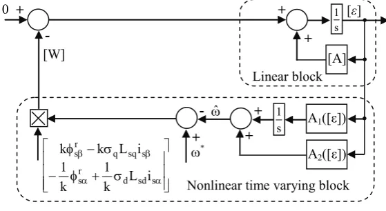
W is the feedback block.In Fig. 2, the term of
[ ]
W is the input and[ ]
ε is the output of the linear feed forward block and it can be easily shown that the linear equivalent system will be completely observable and controllable. The form state Eq. (33) describes the equivalent MRAS in a linear way as it was previously specified that[ ]
εis the main information upon which differences existing between the adjustable model and the reference model can be based.
The asymptotic behavior of the adaptation mechanism is achieved by the simplified condition lim
[
ε(∞)]
=0 for any initialization.0 [ε]
Linear block
s 1
[A]
A1([ε]) s
1
+ +
-+ + -
+
A2([ε])
ωˆ [W]
*
ω+
⎥ ⎥ ⎥
⎦ ⎤
⎢ ⎢ ⎢
⎣ ⎡
σ + φ −
σ − φ
α α
β β
s sd d r
s
s sq q r s
i L k 1 k 1
i L k k
Nonlinear time varying block
Fig. 2. Equivalent representation of nonlinear and time-varying feedback system
The feedback system will be hyper stable for any feedback block of the class satisfying the inequality:
[ ] [ ]
∫
1 ≥−0
2 0 t
t T
dt
W δ
ε for all t1≥t0 (34)
where: δ0is a finite positive constant.
The necessary and sufficient condition for the feedback system to be hyper stable is as follows:
[
sI A]
1) s (
H = − − must be a strictly positive real transfer matrix. From the previous Eq. (33) and Popov inequality, it can be easily shown that the observed speed satisfies the relationship.
[ ]
) A ([ ]
) (A p 1
ˆ = 1 ε + 2 ε
ω (35)
with:
[
(
r) (
s q s d)
q sq]
ss s r s s
s i i L
K
A1= 2 φβφα −φαφβ − αε − βε σ
[
(
r) (
s q s d)
d sd]
s s s r s s
s i i L
K
As the coefficients K1 and K2 of the PI regulator are involved in a non-linear system, there are no rigorous
methods to compute them. Moreover, a linearization around a working point is possible, but it is preferable to find K1 and K2 from simulation of the complete system.
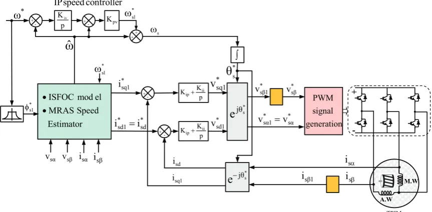
The Block diagram of speed Sensorless ISFOC for TPIM drive as illustrated in Fig. 3, where ω*sl and
* 1 s
φ represent the reference slip angular speed and the reference flux, respectively. The ejθs block performs the coordinate transformation from the reference frame aligned along with the stator flux vector to the stationary reference frame.
* 1 s
φ
+ -
+ -
p K
K ii
ip+
p K
K ii
ip+
* sl
ω
+ - + -
p Kiv
pv
K
+
∫
+ ωs
* 1 sq
i
* sd *
1 sd i
i =
controller speed
IP
ω
ˆ
* s
θ
* s θ j
e
* s θ
j
e−
generation signal PWM
β
s i
α
s
i *
ω
Estimator Speed MRAS
el mod ISFOC
• •
* 1 sq
v
sd i
+
-SPIM A.W
M.W
1 sq
i isβ1
*
α
s *
1
α
s v
v =
* 1
β
s
v *
β
s v
* 1 sd
v
α
s
v vsβ isα isβ * sl
ω
TPIM Fig. 3. Block diagram of speed Sensorless ISFOC for TPIM drive
5. EXPERIMENTAL IMPLEMENTATION
To evaluate the performance of the proposed Sensorless ISFOC speed controller, the control algorithm has been implemented using a dSpace board. The dSpace works on a Matlab/Simlink platform which is a common engineering software and easy to understand and the system is controlled by software running on a dSpace DS1104 processor board. This board contains a Motorola Power PC 603e model that operates at a speed of 250 MHz and a DSP (TMS320F240 – 20 MHz). The controller is interfaced to the real system via graphical I/O-interface blocks provided by dSpace for their DS1104 hardware. Real Time Interface (RTI) is the link between dSpace real time systems and the development software Matlab/Simulink from the Math Works. It extends Real Time Workshop (C code generation) for the automatic implementation of our Simulink. The process can be commanded and monitored via the ControlDesk software of dSpace. The scheme used for the experimental setup is shown in Fig. 4.
The TPIMD is fed by a three-leg voltage source inverter (VSI) using six Insulate Bipolar Transistors (IGBT). As shown in Fig. 4, the one end of the main and auxiliary windings of the motor are connected to one half bridge each. The other ends are tied together and connected to the third half bridge. In order to reduce the ripple current of the TPIMD, a suitable PWM was implemented for the three-leg two-phase output voltages inverter. We propose sinusoidal PWM method instead of Space Vector Pulse Wide Modulation (SVPWM). In a three-leg inverter, two legs control the main and auxiliary winding of the TPIMD voltages and one leg controls the offset voltage. In the experimental test we realise PWM signals for the three leg two-phase inverter in the following way:
• PWM duty cycle is calculated according to vsdref for leg 1,
• PWM duty cycle is calculated according to vsqref for leg 2,
isβ
isα
Algorithm of Sensorless Indirect Stator-Field
Oriented Control
PC Bus DAC
ADC Slave I/O
PWM Driver
Isolation Amplifier
RTI & RTW
DS 1104 Controller Board MATLAB/SIMULINK
Control Desk
Vdc
Magnetic Powder
Brake
Control of the load torque
M.W
A.W
Gate drive
Gate drive
Gate drive
Gate drive
Gate drive
Gate drive
vsα
vsβ
Fig. 4. Scheme used for experimental setup.
0 5 10 15 20 0
200 400 600 800 1000 1200 1400 1600
Temps(s)
Sp
eed (
r/
m
in)
Real speed Estimated speed Reference speed
(a) Simulated (b) Experimental
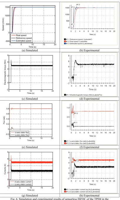
Fig. 5. Simulation and experimental results of sensorless ISFOC of the TPIM to a step, the reference speed from 0 to 1500 r/min
0 5 10 15 20 -500
0 500 1000 1500
Time (s)
Speed (
r/
m
in
)
Real speed Reference speed Estimated speed
(a) Simulated (b) Experimental
0 5 10 15 20
-2 0 2 4 6 8
Time (s)
El
ect
rom
agn
et
ic
to
rq
ue (
N
m
)
(c) Simulated (d) Experimental
0 5 10 15 20
-0.2 0 0.2 0.4 0.6 0.8
Time (s)
Fl
u
x (
w
b)
d-axis stator flux q-axis stator flux
(e) Simulated (f) Experimental
0 5 10 15 20
-2 0 2 4 6 8
Time (s)
C
u
rr
ent
s (
A
)
d-axis stator current q-axis stator current
(g) Simulated (h) Experimental
Figures 6c and d show the estimated electromagnetic torque and in Fig. 6e and f the d, q components of the stator flux are estimated using the measured stator phase currents. The simulation and experimental results presented in Figs. 6e and f show that the stator fluxes converge from their initial values for their final values, respectively (φsd =φs1and φsq =0).
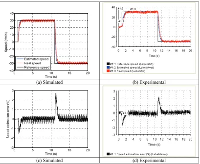
Using the estimated rotor speed as the feedback, the low-speed characteristics of MRAS sensorless control scheme is examined, and the results are shown in Fig. 7. The rotor speed control performance is in the low-speed operation region (30 r/min) of the rotor speed Sensorless drive. It is shown that the proposed algorithm has good speed estimation and adequate vector control characteristics at low rotor speed operation.
0 5 10 15 20
-40 -30 -20 -10 0 10 20 30 40
Time (s)
Sp
ee
d (
r/
m
in
)
Estimated speed Real speed Reference speed
(a) Simulated (b) Experimental
0 5 10 15 20
-3 -2 -1 0 1 2 3
Time (s)
S
p
e
e
d
e
stim
a
tio
n
e
rro
r (%
)
(c) Simulated (d) Experimental
Fig. 7. Simulation and experimental results of sensorless ISFOC of the TPIM for reversing speed reference from 30 r/min to -30 r/min
However, it is noticable that the last results show clearly that the proposed MRAS scheme worked successfully for the Two-Phase Induction Motor Sensorless control algorithm.
6. CONCLUSION
This paper makes a contribution to the issue of sensorless ISFOC of TPIMD. Also, it presents experimental results of an efficient sensorless speed field oriented control for TPIMD. The results were satisfactory and the proposed IP controller gives the system good performances and good dynamic behaviour.
this paper show the effectiveness of observation techniques in order to remove speed sensor in vector control drives at nominal, low and zero motor speed reference controls.
NOMENCLATURE
vsd, vsq d, q-axis stator voltage components isd, isq d, q-axis stator current components ird, irq d, q-axis rotor current components
фsd,фsq d, q-axis stator flux components
фrd,фrq d, q-axis rotor flux components Rsd, Rsq stator windings resistances
Rr rotor resistance
Lsd, Lsq stator self-inductance Lr rotor self-inductances Msrd, Msrq mutual inductances Te, T1 electromagnetic and load torque p =d/dt Laplace operator
ωs , ω synchronous and rotor angular speed
ωsl slip angular speed (ωs -ω)
Ω mechanical rotor speed
np pole-pair number
fr friction coefficient
J total inertia
σd, σq leakage coefficient
τsd, τsd, τr stator and Rotor time constant M. W main winding
A. W auxiliary winding
Kpv proportional gain of the IP speed controller Kiv integral gain of the IP speed controller Kip proportional gain of the PI current controller Kii integral gain of the PI current controller * reference value
REFERENCES
1. Correa, M. R., Jacobina, C. B., Da Silva, E. R. C. & Lima, A. M. N. (2004). Vector control strategies for single-phase induction motor drive systems. IEEE Trans. Ind. Electron., Vol. 51, pp. 1073–1080.
2. Ben Azza, H., Jemli, M., Boussak, M. & Gossa, M. (2011). High performance sensorless speed vector control of SPIM drives with on-line stator resistance estimation. Journ. Simulation Modelling Practice and Theory, Vol. 19, Issue 1, pp. 271–282.
3. Jemli, M., Ben Azza, H., Boussak, M. & Gossa, M. (2009). Sensorless indirect stator field orientation speed control for single-phase induction motor drive. IEEE Trans. on Power Electronics, Vol. 24, No. 6, pp.1618-1627.
4. Correa, M. R., Jacobina, C. B., Lima, A. M. N. & da Silva, E. R. C. (2000). Rotor-flux-oriented control of a single-phase induction motor drive. IEEE Trans. Ind. Electron., Vol. 47, No. 4, pp. 832–841.
5. Blaabjerg, F., Lungeanu, F., Skaug, K. & Tonnes, M. (2004). Two-phase induction motor drives low-cost topologies for TPIM drives in industrial applications. IEEE Trans. Ind. Applic. Mag., pp. 24–32.
6. Lettenmaier, T. A., Nvotny, D. W. & Lipo, T. A. (1991). Single-phase induction motor with an electronically controlled capacitor. IEEE Trans. Ind. Appl., Vol. 27, No. 1, pp. 38–43.
7. Reicy, S. & Vaez-Zadeh, S. (2005). Vector control of single-phase induction machine with maximum torque operation. Proc. IEEE ISIE, Dubrovnik, Coroatia.
9. Correa, M. B. R., Jacobina, C. B., Lima, A. M. N. & da Silva, E. R. C. (2002). Three-leg voltage source inverter for two phase ac motor drive system. IEEE Trans. on Power Electronics, Vol. 9, No. 4, pp. 377-383.
10. Jang, D. H. (2007). PWM methods for two-phase induction motors. IEEE Industry Application Magazine, Vol.13, No. 2, pp. 50-61.
11. Jang, D. H. & Yoon, D. Y. (2003). Space-vector PWM technique for two-phase inverter-fed two phase induction motors. IEEE Trans. Ind. Appl., Vol. 39, No. 2, pp. 542–549.
12. Jabbar, M. A., Khambadkone, A. M. & Yanfeng, Z. (2004). Space-vector modulation in a two-phase induction motor drive for constant-power operation. IEEE Trans. Ind. Electron., Vol. 51, No. 5, pp. 1081–1088.
13. Jemli, M., Ben Azza, H. & Gossa, M. (2009). Real-time implementation of IRFOC for single-phase induction motor drive using dSpace DS 1104 control board. Journ. Simulation Practice and Theory, Vol. 17, pp. 1071– 1080.
14. Kianinezhad, R., Nahid-Mobarakeh, B., Betin, F. & Capolino, G. A. (2009). Robust Sensorless vector control of induction machines. Iranian Journal of Science & Technology, Transaction B: Engineering, Vol. 33, No B2, pp. 133–147.
15. Ebrahimi, M., Rezaei, E., Vaseghi, B. & Danesh, M. (2006). Rotor resistance identification using neural networks for induction motor drives in the case of insensitivity to load variations. Iranian Journal of Science & Technology, Transaction B: Engineering, Vol. 30, No B2, pp. 223–236.
16. Baabjerg, F., Lungeanu, F., Skaug, K. & Tonnes, M. (2004). Low–cost topologies for TPIM drives. IEEE Trans. Ind. Applicat. Mag., pp. 24-32.
17. Vaez-Zadeh, S. & Payman, A. (2003). Design and application of speed estimation for single-phase induction motors. Proc. EPE 2003, Toulouse, ISBN: 90-75815-07-7, pp. 1–10.
18. Payman, A. & Vaez-Zadeh, S. (2004). DSP based speed estimation of single phase induction motors. Proc. 35th Annual IEEE Power Electron. Spec. Conf., Aachen, Germany.
19. Vaez-Zadeh, S. & Payman, A. (2006). Design and analysis of sensorless torque optimization for single phase induction motors. Proc. Int. Journ. Energy Conver. and Manag., Vol. 47, pp. 1464–1477.
20. Vaez-Zadeh, S. & Reicy, H. S. (2005). Sensorless vector control of single-phase induction motor drives. ICEMS. Proc. of the Eighth International Conference on Electrical Machines and Systems, Vol. 3, pp. 1838-1442.
21. Cirrincione, M., Pucci, M., Cirrincione, G. & Capolino, G. A. (2004). A new TLS based MRAS speed estimation with adaptive integration for high performance induction motor drives. IEEE Transaction on Industry Application, Vol. 40, No. 4, pp. 1116-1137.
22. Maurizio, C., Marcello, P., Giansalvo, C. & Capolino, G. A. (2005). An MRAS sensorless technique based on the MCA EXIN + Neuron for high performance induction motor drives. Automatika, ATKAAF, Vol. 46, pp. 59– 72.
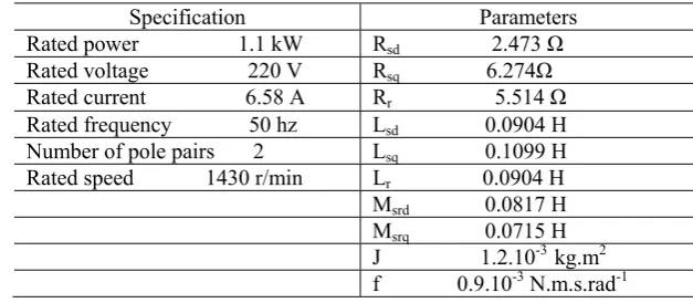
APPENDIX
Table A.1: Two-phase induction machine parameters
Specification Parameters Rated power 1.1 kW Rsd 2.473 Ω