DETERMINATION OF VERTICALITY OF RESERVOIR ENGINEERING STRUCTURE FROM
LASER SCANNER DATA
R. Ehigiator-Irughe
1,*and M. O. Ehigiator
21
D
EPARTMENT OFG
EOMATICS,
U
NIVERSITY OFB
ENIN,
B
ENINC
ITY,
E
DOS
TATE,
NIGERIA.
2
D
EPARTMENT OFP
HYSICS,
B
ENSON–
I
DAHOSAU
NIVERSITY,
GRA.
B
ENINC
ITY.
E
DOS
TATE,
NIGERIA
E-mail addresses:
1[email protected],
2 [email protected]ABSTRACT
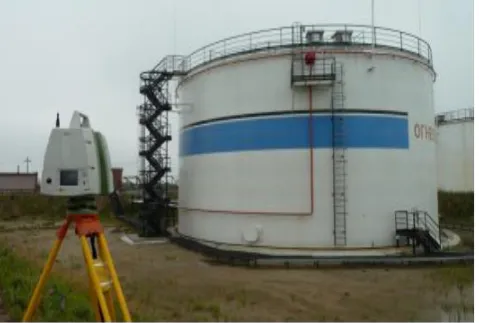
Terrestrial laser scanners (TLS) are used nowadays as Geomatics instruments for various applications. One of these applications is 3D survey and management of oil and gas facilities and other engineering structures. This recent attention is due to the fact that laser scanner has the ability to generate massive amounts of high resolution 3D coordinated cloud points from the surface of the structure. A structure may be scanned from several locations and when these scans are registered together, they will provide complete surface coverage. This paper outlines the use of laser scanner as applied in the determination of the verticality of Reservoir Engineering Structure. The results reveal that the Reservoir did not exceed the allowable tolerance.
Keywords: TLS, Verticality, Reservoir, Georeferencing, Deviation. Scan station.
1. INTRODUCTION
During the last decade, the world of engineering surveying has seen enormous developments in the techniques for spatial data acquisition. One of these developments has been the appearance of terrestrial laser scanning (TLS) technology, which provides the users with the possibilities of direct and automated 3D data capture. TLS employs an indirect ranging principle. The distance, or range from the sensor (a terrestrial laser scanner) to a point on the object surface is determined with high accuracy by measuring the time elapsed between the emission of a laser signal and detection of its portion backscattered from the surface (time-of-flight, TOF). TOF laser scanners employ the following techniques for measuring the travel time of a signal by utilizing different physical effects [1].The basic principle can be presented thus; the distance between the scanner and the object is determined by multiplying the light velocity with half the time-of-flight between the signal transmission and reception. The purpose of this study is to demonstrate the application of TLS in Reservoir verticality check.
Velocity (c) = time-of-flight (d)/t,
Time of flight is a two-way journey i.e. (to and from), therefore, the velocity is given as [2]
By and large, the use of TLS considerably improves a project’s workflow and the quality of the final product. Being itself a very efficient surveying tool, TLS reveals its full potential in combination with some of the traditional surveying techniques. With such a system, the user may acquire data not accessible for TLS alone. One of the most popular examples has been the integration of laser scanners and digital cameras. The camera provides a high-resolution image (texture model), which can be mapped onto a highly-detailed 3D geometric model, derived from the point cloud, to generate photorealistic 3D representation of the objects. However, in most recent TLS, digital cameras have been integrated into the instruments which further enhance the beauty and utilization of the instrument. Another possible combination is the determination of the scanner position and orientation with GNSS, which allows the user to transform data to the desired coordinate system with the minimum expenses [3].
The Reservoir under study of located in Soku gas plant in the south west of Port Harcourt, the capital of Rivers state of Nigeria and about 40km from Port Harcourt. There are a lot o Reservoir in Soku gas plant, but for the purpose of our study, only one of the Reservoirs was scanned.
1.1 Georeferencing
There are two types of Georeferencing during laser data acquisition, these are:
Vol. 36, No. 2, April 2017, pp. 322 – 330
Copyright© Faculty of Engineering, University of Nigeria, Nsukka,
Print ISSN: 0331-8443, Electronic ISSN: 2467-8821
www.nijotech.com
a. Direct method: An important step in data processing
from terrestrial laser scanning (TLS) is
georeferencing, i.e. transformation of the scanner data (point clouds) into a real-world coordinate system, which is important for their integration with other geospatial data. An efficient approach for this is direct georeferencing, whereby the position and orientation of the scanner can be determined in the field, similarly to the working routine of total stations [3]. The back target and the instrument station are setup onknown points and other target points are seen as new points whose position can be determined to an accuracy of less than 1cm. Results have shown that it is possible to achieve the coordinate accuracy of better than 1 cm at the object distance of up to 50 m. This is comparable to the accuracy of conventional direct Total Station methods of control extension i.e. when the scanner is centered over a known point.
b. Indirect method: one most commonly makes use of
the targets with known coordinates in the external system, to transform the point clouds to this system. The relationship between the two systems is described, as in the case with two scanner coordinate systems, by the 6-transformation parameters. The scale factor has been shown to be irrelevant in transformation. These parameters are often called exterior orientation parameters (EOPs). In order to uniquely determine the 6 EOPs, one needs to know at least 6 coordinates in both systems, distributed over 3 points not on the same line. In practice, one makes use of 3 or more targets with known 3D coordinates placed on or near the object scanned. These targets are called control points [3]. Their coordinates may be determined, e.g. from a total station survey, with GPS or from a photogrammetric survey. The targets should be well distributed, with a good variation in depth, and not lie on the same line. This georeferencing approach is currently the most precise one and widely use. Table 1 represent TLS target system.
As a result of serious environmental hazards resulting from Reservoir failures there is need to carryout periodic monitoring. Reservoirs used for crude oil are above ground storage. These above surface storages are usually constructed of steel and over the years many of the Reservoirs have corroded and tilted thereby causing leak and total failure [4]. The resultant failure or leak will cause petroleum products contaminating the soil, ground water and the environment.
Leaking of failed Reservoir can be a source of groundwater problem as the petroleum which they carry contains toxic compounds including benzene, toluene, xylene and ethylene dibromide. These compounds are
risks including nervous system damage, reproductive problem and immune system depression [5]. The soils and geological condition at the Reservoir locations can also affect ground water contamination.
2. VERTICALITY CHECK USING TERRESTRIAL LASER SCANNER
The structural integrity check of Various Engineering Structure is of major concern to both local community and environmentalists. Although API 653 remain the industry standard relative to Reservoir inspection and maintenance, the frequency of testing and inspection can also be affected by various state and local regulations [4]. Before the advent of TLS, conventional methods have been adequately deployed in the determination of the verticality of Reservoir, the recent method tend to give better advantages as there is the possibility of viewing the structure from various axes i.e. at horizontal, vertical and inclined axes [6]. This is only possible after scanner and creation of model space. The model space for the Reservoir under study is presented in Figure 2. The true top-bottom verticality of the tanks and their perpendicularity were scanned and direct method of Georeferencing was adopted. Four scan worlds were created and the distances from the TLS to the Reservoir are presented in Table 1.
Figure 1:Terrestial laser scanner Targets
Figure 3: Subdivision of Reservoir
Figure 4: Reservoir Model Space
Table 1: Distances from TLS to object
From To
Scan Station P1 13.775m
Scan Station P2 14.972m
Scan Station P3 19.470m
Scan Station P4 20.944m
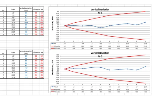
Table 2: Height and Vertical Deviation
No Height Vertical deviation (mm) Allowance (mm)
1 5.29 0.0 0.0 0.0
2 7.29 0.0 15.0 -15.0
3 9.29 -2.1 25.0 -25.0
4 11.29 -8.1 35.0 -35.0
5 13.29 -9.8 45.0 -45.0
6 15.29 -21.8 55.0 -55.0
From the four scan worlds, model space was created and the top to bottom view was enhanced using cyclone 8.1 and the verticality was determined by subdividing the Reservoir in 18 points representing the designed as monitoring stations as presented below in Figure 3.
3. ANALYSIS AND PRESENTATION OF RESULTS
P1 to P6 as shown on the Reservoir are points on the scan worlds were verticality were Measured and presented in Table 2 below. Graphs of verticality (1 – 18) below represence the Verticaldeviation of the Reservoir under study fromaxis number 1 to number 18. The subdivision of theReservoir into 18 axes represent the designed motoring points on the Reservoir. The red line on both side of the each graph is the allowable deviation of the Reservoir lying between 0 to+75mm and 0 to -75mm respectively and the blue line is the actual verticality of the Reservoir.Verticality of the Reservoir was determined at 10 segments with the first segment at a height of
5.29m and the 10th segment at height of 23.18m in all
cases.
1 5.29 0.0 0.0 0.0
2 7.29 1.5 15.0 -15.0
3 9.29 -0.7 25.0 -25.0
4 11.29 1.4 35.0 -35.0
5 13.29 -10.6 45.0 -45.0
6 15.29 0.0 55.0 -55.0
7 17.29 6.5 60.0 -60.0
8 19.29 11.4 65.0 -65.0
9 21.29 4.8 70.0 -70.0
10 23.18 18.8 75.0 -75.0
1 5.29 0.0 0.0 0.0
2 7.29 1.6 15.0 -15.0
3 9.29 1.5 25.0 -25.0
4 11.29 8.0 35.0 -35.0
5 13.29 8.5 45.0 -45.0
6 15.29 -4.9 55.0 -55.0
7 17.29 -2.8 60.0 -60.0
8 19.29 0.0 65.0 -65.0
9 21.29 -4.9 70.0 -70.0
10 23.18 12.3 75.0 -75.0
Height vertical deviatioin
(mm) Allowable, мм
Height vertical deviatioin
(mm) Allowable, мм no
no
1 2 3 4 5 6 7 8 9 10
Tilt 0.0 1.5 -0.7 1.4 -10.6 0.0 6.5 11.4 4.8 18.8 Allowable 0.0 15.0 25.0 35.0 45.0 55.0 60.0 65.0 70.0 75.0 Allowable 0.0 -15.0 -25.0 -35.0 -45.0 -55.0 -60.0 -65.0 -70.0 -75.0
-75.0 -65.0 -55.0 -45.0 -35.0 -25.0 -15.0 -5.0 5.0 15.0 25.0 35.0 45.0 55.0 65.0 75.0
D
e
vi
a
ti
o
n
,
мм
Vertical Deviation № 1
1 2 3 4 5 6 7 8 9 10
Actual 0.0 1.6 1.5 8.0 8.5 -4.9 -2.8 0.0 -4.9 12.3 Allowable 0.0 15.0 25.0 35.0 45.0 55.0 60.0 65.0 70.0 75.0 Allowable 0.0 -15.0 -25.0 -35.0 -45.0 -55.0 -60.0 -65.0 -70.0 -75.0
-75.0 -65.0 -55.0 -45.0 -35.0 -25.0 -15.0 -5.0 5.0 15.0 25.0 35.0 45.0 55.0 65.0 75.0
D
e
vi
a
ti
o
n
,
мм
1 5.29 0.0 0.0 0.0 2 7.29 6.2 15.0 -15.0 3 9.29 -1.1 25.0 -25.0 4 11.29 -3.4 35.0 -35.0 5 13.29 -3.0 45.0 -45.0 6 15.29 -10.0 55.0 -55.0 7 17.29 -0.3 60.0 -60.0
8 19.29 5.4 65.0 -65.0
9 21.29 4.6 70.0 -70.0
10 23.18 16.9 75.0 -75.0
1 5.29 0.0 0.0 0.0
2 7.29 0.0 15.0 -15.0 3 9.29 -2.1 25.0 -25.0 4 11.29 -8.1 35.0 -35.0 5 13.29 -9.8 45.0 -45.0 6 15.29 -21.8 55.0 -55.0 7 17.29 -26.5 60.0 -60.0 8 19.29 -29.0 65.0 -65.0 9 21.29 -17.9 70.0 -70.0 10 23.18 -16.0 75.0 -75.0
vertical deviatioin (mm) Allowable, мм Height vertical deviatioin
(mm)
no Allowable, мм
no Height
1 2 3 4 5 6 7 8 9 10
Actual 0.0 6.2 -1.1 -3.4 -3.0 -10.0 -0.3 5.4 4.6 16.9 Allowable 0.0 15.0 25.0 35.0 45.0 55.0 60.0 65.0 70.0 75.0 Allowable 0.0 -15.0 -25.0 -35.0 -45.0 -55.0 -60.0 -65.0 -70.0 -75.0
-75.0 -65.0 -55.0 -45.0 -35.0 -25.0 -15.0 -5.0 5.0 15.0 25.0 35.0 45.0 55.0 65.0 75.0
D
e
vi
a
ti
o
n
,
мм
Vertical Deviation № 3
1 2 3 4 5 6 7 8 9 10
Actual 0.0 0.0 -2.1 -8.1 -9.8 -21.8 -26.5 -29.0 -17.9 -16.0 Allowable 0.0 15.0 25.0 35.0 45.0 55.0 60.0 65.0 70.0 75.0 Allowable 0.0 -15.0 -25.0 -35.0 -45.0 -55.0 -60.0 -65.0 -70.0 -75.0
-75.0 -65.0 -55.0 -45.0 -35.0 -25.0 -15.0 -5.0 5.0 15.0 25.0 35.0 45.0 55.0 65.0 75.0
D
e
vi
a
ti
o
n
,
мм
Vertical Deviation № 4
1 5.29 0.0 0.0 0.0
2 7.29 3.4 15.0 -15.0
3 9.29 6.2 25.0 -25.0
4 11.29 3.3 35.0 -35.0
5 13.29 0.0 45.0 -45.0
6 15.29 -2.9 55.0 -55.0
7 17.29 -2.0 60.0 -60.0
8 19.29 -3.9 65.0 -65.0
9 21.29 -6.1 70.0 -70.0
10 23.18 20.1 75.0 -75.0
1 5.29 0.0 0.0 0.0
2 7.29 6.6 15.0 -15.0
3 9.29 5.0 25.0 -25.0
4 11.29 0.4 35.0 -35.0
5 13.29 -1.0 45.0 -45.0
6 15.29 -10.3 55.0 -55.0
7 17.29 -3.5 60.0 -60.0
8 19.29 -3.2 65.0 -65.0
9 21.29 0.0 70.0 -70.0
10 23.18 24.4 75.0 -75.0
no Height
vertical deviatioin (mm) Allowable, мм
no Height
vertical deviatioin (mm) Allowable, мм
1 2 3 4 5 6 7 8 9 10
Tilt 0.0 3.4 6.2 3.3 0.0 -2.9 -2.0 -3.9 -6.1 20.1 Allowable 0.0 15.0 25.0 35.0 45.0 55.0 60.0 65.0 70.0 75.0 Allowable 0.0 -15.0 -25.0 -35.0 -45.0 -55.0 -60.0 -65.0 -70.0 -75.0
-75.0 -65.0 -55.0 -45.0 -35.0 -25.0 -15.0 -5.0 5.0 15.0 25.0 35.0 45.0 55.0 65.0 75.0
D
e
vi
a
ti
o
n
,
мм
Vertical Deviation № 5
1 2 3 4 5 6 7 8 9 10
Actual 0.0 6.6 5.0 0.4 -1.0 -10.3 -3.5 -3.2 0.0 24.4 Allowable 0.0 15.0 25.0 35.0 45.0 55.0 60.0 65.0 70.0 75.0 Allowable 0.0 -15.0 -25.0 -35.0 -45.0 -55.0 -60.0 -65.0 -70.0 -75.0
-75.0 -65.0 -55.0 -45.0 -35.0 -25.0 -15.0 -5.0 5.0 15.0 25.0 35.0 45.0 55.0 65.0 75.0
D
e
vi
a
ti
o
n
,
мм
1 5.29 0.0 0.0 0.0
2 7.29 -3.9 15.0 -15.0
3 9.29 -4.0 25.0 -25.0
4 11.29 -2.6 35.0 -35.0
5 13.29 -5.7 45.0 -45.0
6 15.29 -7.9 55.0 -55.0
7 17.29 -1.9 60.0 -60.0
8 19.29 -5.8 65.0 -65.0
9 21.29 -7.2 70.0 -70.0
10 23.18 18.9 75.0 -75.0
1 5.29 0.0 0.0 0.0
2 7.29 2.5 15.0 -15.0
3 9.29 -3.2 25.0 -25.0
4 11.29 -3.0 35.0 -35.0
5 13.29 -6.3 45.0 -45.0
6 15.29 -17.7 55.0 -55.0
7 17.29 -12.3 60.0 -60.0
8 19.29 -18.7 65.0 -65.0
9 21.29 -26.7 70.0 -70.0
10 23.18 -18.8 75.0 -75.0
no Height
vertical deviatioin (mm) Allowable, мм
no Height
vertical deviatioin (mm) Allowable, мм
1 2 3 4 5 6 7 8 9 10
Actual 0.0 -3.9 -4.0 -2.6 -5.7 -7.9 -1.9 -5.8 -7.2 18.9
Allowable 0.0 15.0 25.0 35.0 45.0 55.0 60.0 65.0 70.0 75.0
Allowable 0.0 -15.0 -25.0 -35.0 -45.0 -55.0 -60.0 -65.0 -70.0 -75.0
-75.0 -65.0 -55.0 -45.0 -35.0 -25.0 -15.0 -5.0 5.0 15.0 25.0 35.0 45.0 55.0 65.0 75.0
D
e
vi
a
ti
o
n
,
мм
Vertical Deviation
№ 7
1 2 3 4 5 6 7 8 9 10
Actual 0.0 2.5 -3.2 -3.0 -6.3 -17.7 -12.3 -18.7 -26.7 -18.8
Allowable 0.0 15.0 25.0 35.0 45.0 55.0 60.0 65.0 70.0 75.0
Allowable 0.0 -15.0 -25.0 -35.0 -45.0 -55.0 -60.0 -65.0 -70.0 -75.0
-75.0 -65.0 -55.0 -45.0 -35.0 -25.0 -15.0 -5.0 5.0 15.0 25.0 35.0 45.0 55.0 65.0 75.0
D
e
vi
a
ti
o
n
,
мм
Vertical Deviation
№ 8
1 5.29 0.0 0.0 0.0
2 7.29 1.8 15.0 -15.0
3 9.29 -1.3 25.0 -25.0
4 11.29 0.0 35.0 -35.0
5 13.29 -2.0 45.0 -45.0
6 15.29 -10.5 55.0 -55.0
7 17.29 -5.1 60.0 -60.0
8 19.29 0.0 65.0 -65.0
9 21.29 0.0 70.0 -70.0
10 23.18 4.6 75.0 -75.0
1 5.29 0.0 0.0 0.0
2 7.29 3.2 15.0 -15.0
3 9.29 -1.0 25.0 -25.0
4 11.29 -1.0 35.0 -35.0
5 13.29 -7.4 45.0 -45.0
6 15.29 -22.6 55.0 -55.0
7 17.29 -22.2 60.0 -60.0
8 19.29 -36.0 65.0 -65.0
9 21.29 -55.7 70.0 -70.0
10 23.18 -6.6 75.0 -75.0
no Height
vertical deviatioin
(mm) Allowable, мм no Height
vertical deviatioin
(mm) Allowable, мм
1 2 3 4 5 6 7 8 9 10
Actual 0.0 1.8 -1.3 0.0 -2.0 -10.5 -5.1 0.0 0.0 4.6 Allowable 0.0 15.0 25.0 35.0 45.0 55.0 60.0 65.0 70.0 75.0 Allowable 0.0 -15.0 -25.0 -35.0 -45.0 -55.0 -60.0 -65.0 -70.0 -75.0
-75.0 -65.0 -55.0 -45.0 -35.0 -25.0 -15.0 -5.0 5.0 15.0 25.0 35.0 45.0 55.0 65.0 75.0
D
e
vi
a
ti
o
n
,
мм
Vertical Deviation № 9
1 2 3 4 5 6 7 8 9 10
Actual 0.0 3.2 -1.0 -1.0 -7.4 -22.6 -22.2 -36.0 -55.7 -6.6 Allowable 0.0 15.0 25.0 35.0 45.0 55.0 60.0 65.0 70.0 75.0 Allowable 0.0 -15.0 -25.0 -35.0 -45.0 -55.0 -60.0 -65.0 -70.0 -75.0
-75.0 -65.0 -55.0 -45.0 -35.0 -25.0 -15.0 -5.0 5.0 15.0 25.0 35.0 45.0 55.0 65.0 75.0
D
e
vi
a
ti
o
n
,
мм
1 5.29 0.0 0.0 0.0 2 7.29 6.1 15.0 -15.0 3 9.29 3.7 25.0 -25.0
4 11.29 9.5 35.0 -35.0
5 13.29 5.4 45.0 -45.0
6 15.29 2.8 55.0 -55.0
7 17.29 6.8 60.0 -60.0
8 19.29 19.0 65.0 -65.0 9 21.29 13.8 70.0 -70.0 10 23.18 25.6 75.0 -75.0
1 5.29 0.0 0.0 0.0
2 7.29 2.7 15.0 -15.0 3 9.29 -1.9 25.0 -25.0 4 11.29 -5.9 35.0 -35.0 5 13.29 -7.6 45.0 -45.0 6 15.29 -16.9 55.0 -55.0 7 17.29 -7.7 60.0 -60.0
8 19.29 0.0 65.0 -65.0
9 21.29 2.1 70.0 -70.0
10 23.18 19.0 75.0 -75.0 no Height
vertical deviatioin
(mm) Allowable, мм
no Height
vertical deviatioin
(mm) Allowable, мм
1 2 3 4 5 6 7 8 9 10
Actual 0.0 6.1 3.7 9.5 5.4 2.8 6.8 19.0 13.8 25.6
Allwable 0.0 15.0 25.0 35.0 45.0 55.0 60.0 65.0 70.0 75.0
Allowable 0.0 -15.0 -25.0 -35.0 -45.0 -55.0 -60.0 -65.0 -70.0 -75.0
-75.0 -65.0 -55.0 -45.0 -35.0 -25.0 -15.0 -5.0 5.0 15.0 25.0 35.0 45.0 55.0 65.0 75.0
D
e
vi
a
ti
o
n
,
мм
Vertical Deviation № 11
1 2 3 4 5 6 7 8 9 10
Actual 0.0 2.7 -1.9 -5.9 -7.6 -16.9 -7.7 0.0 2.1 19.0
Allowable 0.0 15.0 25.0 35.0 45.0 55.0 60.0 65.0 70.0 75.0
Allowable 0.0 -15.0 -25.0 -35.0 -45.0 -55.0 -60.0 -65.0 -70.0 -75.0
-75.0 -65.0 -55.0 -45.0 -35.0 -25.0 -15.0 -5.0 5.0 15.0 25.0 35.0 45.0 55.0 65.0 75.0
D
e
vi
a
ti
o
n
,
мм
Vertical Deviation № 12
1 5.29 0.0 0.0 0.0
2 7.29 -3.7 15.0 -15.0 3 9.29 -3.7 25.0 -25.0 4 11.29 -2.3 35.0 -35.0 5 13.29 -0.8 45.0 -45.0 6 15.29 -10.2 55.0 -55.0 7 17.29 -8.8 60.0 -60.0 8 19.29 -13.3 65.0 -65.0 9 21.29 -6.8 70.0 -70.0 10 23.18 -17.7 75.0 -75.0
1 5.29 0.0 0.0 0.0
2 7.29 0.0 15.0 -15.0 3 9.29 -2.4 25.0 -25.0 4 11.29 -6.3 35.0 -35.0 5 13.29 -13.1 45.0 -45.0 6 15.29 -20.5 55.0 -55.0 7 17.29 -20.6 60.0 -60.0 8 19.29 -20.8 65.0 -65.0 9 21.29 -18.1 70.0 -70.0 10 23.18 -22.5 75.0 -75.0
Height vertical deviatioin (mm)
no Allowable, мм
no Height
vertical deviatioin
(mm) Allowable, мм
1 2 3 4 5 6 7 8 9 10
Actual 0.0 -3.7 -3.7 -2.3 -0.8 -10.2 -8.8 -13.3 -6.8 -17.7
Allowable 0.0 15.0 25.0 35.0 45.0 55.0 60.0 65.0 70.0 75.0
Allowable 0.0 -15.0 -25.0 -35.0 -45.0 -55.0 -60.0 -65.0 -70.0 -75.0
-75.0 -65.0 -55.0 -45.0 -35.0 -25.0 -15.0 -5.0 5.0 15.0 25.0 35.0 45.0 55.0 65.0 75.0
D
e
v
ia
ti
o
n
,
мм
Vertical Deviation № 13
1 2 3 4 5 6 7 8 9 10
Actual 0.0 0.0 -2.4 -6.3 -13.1 -20.5 -20.6 -20.8 -18.1 -22.5
Allowable 0.0 15.0 25.0 35.0 45.0 55.0 60.0 65.0 70.0 75.0
Allowable 0.0 -15.0 -25.0 -35.0 -45.0 -55.0 -60.0 -65.0 -70.0 -75.0
-75.0 -65.0 -55.0 -45.0 -35.0 -25.0 -15.0 -5.0 5.0 15.0 25.0 35.0 45.0 55.0 65.0 75.0
D
e
v
ia
ti
o
n
,
мм
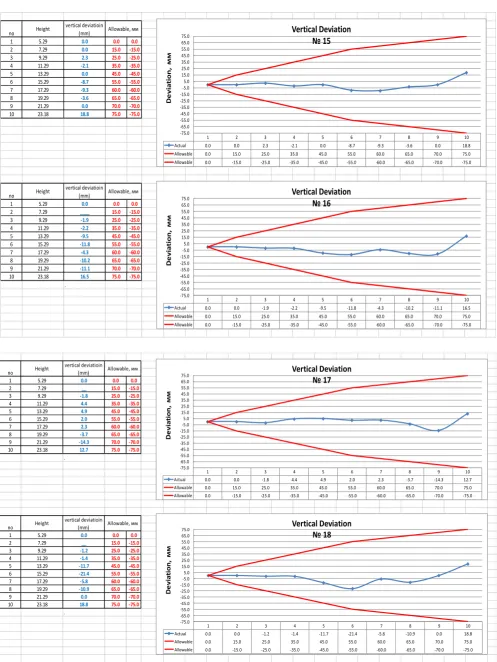
Figure 5: Reservoir Verticality
For graph № , the maximum deviation occurred at the
10th segment with a numerical value of 18mmand
minimum at the 5th segment with value of -10.6mm. For
№ , the maximum devaition Occurredat the 0th
segment with a value of 12.3mm and minimum at the 6th
and 9th segments Respectivelywith a numerical value of
-1 5.29 0.0 0.0 0.0
2 7.29 0.0 15.0 -15.0 3 9.29 2.3 25.0 -25.0
4 11.29 -2.1 35.0 -35.0
5 13.29 0.0 45.0 -45.0
6 15.29 -8.7 55.0 -55.0
7 17.29 -9.3 60.0 -60.0
8 19.29 -3.6 65.0 -65.0
9 21.29 0.0 70.0 -70.0
10 23.18 18.8 75.0 -75.0
1 5.29 0.0 0.0 0.0
2 7.29 ____ 15.0 -15.0 3 9.29 -1.9 25.0 -25.0
4 11.29 -2.2 35.0 -35.0
5 13.29 -9.5 45.0 -45.0
6 15.29 -11.8 55.0 -55.0
7 17.29 -4.3 60.0 -60.0
8 19.29 -10.2 65.0 -65.0 9 21.29 -11.1 70.0 -70.0 10 23.18 16.5 75.0 -75.0
. no Height
vertical deviatioin
(mm) Allowable, мм
no Height
vertical deviatioin
(mm) Allowable, мм
1 2 3 4 5 6 7 8 9 10
Actual 0.0 0.0 2.3 -2.1 0.0 -8.7 -9.3 -3.6 0.0 18.8 Allowable 0.0 15.0 25.0 35.0 45.0 55.0 60.0 65.0 70.0 75.0 Allowable 0.0 -15.0 -25.0 -35.0 -45.0 -55.0 -60.0 -65.0 -70.0 -75.0
-75.0 -65.0 -55.0 -45.0 -35.0 -25.0 -15.0 -5.0 5.0 15.0 25.0 35.0 45.0 55.0 65.0 75.0
D
e
v
ia
ti
o
n
,
мм
Vertical Deviation № 15
1 2 3 4 5 6 7 8 9 10
Actual 0.0 0.0 -1.9 -2.2 -9.5 -11.8 -4.3 -10.2 -11.1 16.5 Allowable 0.0 15.0 25.0 35.0 45.0 55.0 60.0 65.0 70.0 75.0 Allowable 0.0 -15.0 -25.0 -35.0 -45.0 -55.0 -60.0 -65.0 -70.0 -75.0
-75.0 -65.0 -55.0 -45.0 -35.0 -25.0 -15.0 -5.0 5.0 15.0 25.0 35.0 45.0 55.0 65.0 75.0
D
e
v
ia
ti
o
n
,
мм
Vertical Deviation № 16
1 5.29 0.0 0.0 0.0
2 7.29 __ 15.0 -15.0
3 9.29 -1.8 25.0 -25.0
4 11.29 4.4 35.0 -35.0
5 13.29 4.9 45.0 -45.0
6 15.29 2.0 55.0 -55.0
7 17.29 2.3 60.0 -60.0
8 19.29 -3.7 65.0 -65.0
9 21.29 -14.3 70.0 -70.0
10 23.18 12.7 75.0 -75.0
.
1 5.29 0.0 0.0 0.0
2 7.29 __ 15.0 -15.0
3 9.29 -1.2 25.0 -25.0
4 11.29 -1.4 35.0 -35.0
5 13.29 -11.7 45.0 -45.0
6 15.29 -21.4 55.0 -55.0
7 17.29 -5.8 60.0 -60.0
8 19.29 -10.9 65.0 -65.0
9 21.29 0.0 70.0 -70.0
10 23.18 18.8 75.0 -75.0
.
no Height
vertical deviatioin
(mm) Allowable, мм
no Height
vertical deviatioin
(mm) Allowable, мм
1 2 3 4 5 6 7 8 9 10
Actual 0.0 0.0 -1.8 4.4 4.9 2.0 2.3 -3.7 -14.3 12.7 Allowable 0.0 15.0 25.0 35.0 45.0 55.0 60.0 65.0 70.0 75.0 Allowable 0.0 -15.0 -25.0 -35.0 -45.0 -55.0 -60.0 -65.0 -70.0 -75.0
-75.0 -65.0 -55.0 -45.0 -35.0 -25.0 -15.0 -5.0 5.0 15.0 25.0 35.0 45.0 55.0 65.0 75.0
D
e
v
ia
ti
o
n
,
мм
Vertical Deviation № 17
1 2 3 4 5 6 7 8 9 10
Actual 0.0 0.0 -1.2 -1.4 -11.7 -21.4 -5.8 -10.9 0.0 18.8 Allowable 0.0 15.0 25.0 35.0 45.0 55.0 60.0 65.0 70.0 75.0 Allowable 0.0 -15.0 -25.0 -35.0 -45.0 -55.0 -60.0 -65.0 -70.0 -75.0
-75.0 -65.0 -55.0 -45.0 -35.0 -25.0 -15.0 -5.0 5.0 15.0 25.0 35.0 45.0 55.0 65.0 75.0
D
e
v
ia
ti
o
n
,
мм
4.9mm. Graph № 3 shows similarity with graphs №
and № withvalues of 6.9mm and -10mm and the 10th
and 6th segment respectively. Graph № 4 shows
differcharacteristic from that of graphs № to № 3. In all the segments, negative values hereobtained.For graphs № 5, 6 and 7 appears to follow the same vertical deviation similar to that ofgraphs № to№ 3, similarly, graphs № 9, , , 5, 6, 7 and 18 also follows the same patternas that of graphs№ to № 3, while graphs № 8, 0, 3, and 4 follewed the deviation pattern asgraph № 4. In all, non of the graphs presented below exceed the allowable.
4. CONCLUSIONS
The history of Reservoir disaster throughout the world reveals that problems often arise undetected due to inaccurate evaluation of both foundation and Reservoir defects. The soil, water and concrete in a Reservoir at the foundation bed are materials of different properties. The level of interaction cannot be underestimated. Although the interaction is not spontaneous, the solvent property of water can undermine the configuration of the soils upon which the Structure rests. Monitoring and inspection of Reservoir will ensure continuous safety of the structure so as to avoid the danger arising from environmental degradation as a result of Reservoir failure.
From the graphs presented above, the results revealed that the Reservoir verticality under study is stable as none of the segments exceeded tolerant deviations. We have demonstrated that TLS is suitable and can be used to determine the characteristics of a Reservoir.
Monitoring of the Reservoir should be carried out more frequently for early detection of symptoms and deficiencies and remedial measures taken as quickly as possible.
5. ACKNOWLEDGEMENT
The authors are grateful to Surv. Ken Udeh for providing the scanned data.
6. REFERENCES
1. Alba M., Scaioni M. Comparison of techniques for
terrestrial laser scanning data georeferencing applied
to 3-D modelling of cultural heritage. In: Proceedings
of the 2nd ISPRS International Workshop 3D-ARCH 007: “3D Virtual Reconstruction and Visualization of Complex Architectures”, Zurich, Switzerland, – 13
July. http://www.isprs.org/publications/
archives.html. 2007.
2. Alba M, Giussani A., Roncoroni F., Scaioni M. Strategies
for direct georeferencing of Riegl LMS-Z420i data. In:
Gruen A, Kahmen H (eds.) Optical 3-D Measurement
Techniques. 2005.
3. Yuriy Reshetyuk, Self-calibration and direct
georeferencing in terrestrial laser scanning. Doctoral thesis in Infrastructure, Geodesy Royal Institute of Technology (KTH) Department of Transport and Economics Division of Geodesy 100 44 Stockholm. 2009.
4. Boehler, W. and Marbs, A.: Investigating Laser
Scanner Accuracy. URL:
http://scanning.fh-mainz.de/scannertest/results300305.pdf.
5. Babic L, Pribicevic B and Dapo A. Application of 3D
Laser scanning for Deformation measurements on
Industrial objects, Proceedings FIG congress, 16-21
June 2014, Kuala-Lumpur, http/www.fig.org, 2014.
6. Besl P. J and McKay N. D A method for registration of
3D shapes, IEEE Transactions on Pattern Analysis and
Machine Intelligence 14(2) pp 239-256. 1992.
7. Godbout S, Marquers M, Fafard M and Picard A
Analytical determination of Internal forces in a cylindrical tank wall for Soil Liquid and Vehicle Load 1 m of mechanical 2003.
8. Shoffield W “Engineering Surveying”
Butterworth-Heinemann PhD published Oxford 1993.
9. Shell Petroleum Development Company of Nigeria
http://www.nigerianoil-gas.com/industry profile
2000.
10.Shell Petroleum Development Company Oil Industry
profile, Nigeria
http://www.nigerianoil-gas.com/industryprofile 2003.
11.Wehr A, Lohr U. Airborne laser scanning – an
introduction and overview. ISPRS J Photogramm and
Remote Sens 54: 68 – 82 1999.
12.World Health Organization WHO Report