Massive Multiuser Multiple-Input and Multiple-Output
Wireless Communication System on Antenna Array
B.Gayathri
#1, R.Anitha
#21
Student,Master of Computer Application, S.A Engineering College, Chennai-77. [email protected]
2
Assistant Professor, Department of Computer Application, S.A Engineering College, Chennai-77.
Abstract —This paper is about massive multiple-inputs and multiple-output technology based on the wireless 5G communication system. Surface of antenna in communication engineering applications array deployment regions are usually uneven [1]. In the real antenna deployment scenarios, a spatial distance of massive Multiple-Input and Multiple-Output (MIMO) antenna arrays is usually irregular [2]. The effect of mutual coupling on irregular antenna array is by the channel correlation model and receiver gain. Our result provides guidelines for the massive MIMO antenna deployment in real scenarios. A large number of antennas at the transmitter impose a high computation burden and high hardware overloads. In this communication, we present a dual-polarized antenna array with 144 ports for massive MIMO operation at 3.7 GHZ. The presented MIMO concept can be utilized inorder to improve the angular resolution and to reduce the side lobe level for a given number of transmitting and receiving antenna.
Keywords —Beam Forming; Antenna Array; Massive Multiple-Input and Multiple-Output
1.
Introduction
The dual-polarization considering uneven surface of antenna deployment regions, a massive MIMO communication system with an irregular antenna array is first proposed and formulated. However, these antenna arrays were mainly studied in the field of phased arrays and have never been discussed for a massive communication system. When massive MIMO antenna has to be deployed on an uneven surface, the spatial distance between adjacent antennas are not expected to be perfectly uniform. The use of very large arrays leads to increased hardware complexity in terms of radio-frequency chain [3]. The power coming from one of the two ports are split into two equal ones which are guided to the two bow-tie apertures on the ground. The other advantages of the symmetric layout of the proposed antenna units are the ability to eliminate mutual coupling between horizontal and vertical polarization modes. In this contribution, MIMO concept based on antenna arrays with fractal boundaries are presented and compared to MIMO configurations based on
orthogonally positioned linear antenna array [4]. Finally, the performance of a fractal MIMO concept with 21 transmitting antennas and 21 receiving antennas have been experimentally evaluated by measurements [5].
2.
Existing System
With the massive MIMO technology, emerging in 5G mobile communication system, hundreds of antenna has to be deployed on the base station tower or the surface of a building. Compared to antenna configurations based on two linear arrays, the other symmetric layout of the proposed antenna unit is the ability to eliminate the mutual coupling between the horizontal and vertical polarization modes. Especially as one of the most promising 5G technology, massive MIMO has been proved to have the huge advantage on spectral efficiency, energy efficiency, and robustness compared with traditional MIMO system [6][7]. With over 100 antenna ports to be implemented at the base station, massive MIMO has brought for significant challenges. In this communication a low profile stacked patch antenna unit designed with four apertures through four coupling strips to excite four paths with signals on two ends of each coupling strip exciting the vertical polarization mode. When the horizontal polarization mode is being excited, the signals are of same amplitude and in-phase because of the symmetric layout; thus each of the vertical coupling strips is excited by the horizontal mutual coupling signals in common mode .To intuitively illustrate the spatial distance among the irregular antenna array, we project the antenna distance deployed on the uneven surface. The circular area does not depend on the actual shape of the antenna deployed regions. Similarly, another random process can be used for the modelling of irregular antenna distribution according to the specified requirements.
2.1 Disadvantages
Following are the disadvantages of Massive MIMO system.
High signal processing complexity due to the utilization of a large number of antennas and multiplexing of User Equipments (UE) or Mobile subscribers(MS).
Sensitive to beam alignment, as extremely narrower beam is used which is sensitive for the movement of Mobile Station (MS) or swaying of the antenna array.
3.
Proposed System
In this paper, we propose beam forming. If you can get beam forming on your router, that’s certainly a good thing there’s no downside to getting beam forming. If some problem may arise, we have to increase the spectrum efficiency of the antenna to avoid it. For that we need to construct the number of antenna on the base station. It can also reduce the traffic that occurred on the network. The irregular antenna improves the spectrum efficiency to 15-25 bit/sec level. It saves the time level of 10-20 times energy in wireless communication system.
3.1 Advantages
High spectrum efficiency due to large
multiplexing gain as well as antenna array gain.
Radiated energy on MS/UE help for High energy efficiency.
Large diversity gain increase reliability.
Easy scheduling scheme.
Robustness to individual element failure.
4.
Methodology
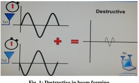
Each phase of data stream is transmitted by all antennas at dissimilar times will be calculated. Therefore, to get these different signals, interfere at a particular location in space (receiver the location), thereby enhancing the signal strength at that location. Two popular techniques are used in MIMO systems are Receive and transmit. Diversity mitigates fading and significantly improves link quality. Spatial multiplexing yields a substantial increase in spectral efficiency. An access point is used however it is possible to steal the radio frequency energy towards a specific device within the network using beam forming. The Diagrams show the ideas, for example, an access point capable of generating lobes and power of energy directed to the specific point with the network we can create a constructive combination of energy and destructive combination. Those can be useful when we use multi-user MIMO junction to the beam forming in helping to separate different clients. But let us take how the structure beam forming works. From the access point, we transmit same radio frequency energy in the form of waves which is possible to enhance and transmit two waves of energy and obviously, it can create waves which increase the amplitude and signal strength of the receiving side. But the problem arise is due to the signal path, two beam of
rotation energy and if two signal arrives at the same position we have the destructive combination.
Fig. 1: Destructive in beam forming
Fig. 2: Constructive in beam forming
Fig. 3: Beam forming in 4*4 antenna
4.1 Beam Forming using Explicit Feedback
Beam forming creates correct characters on the received point from the optimal signal strength. When the system is moving like a mobile device, the matrix is to be continuously added whether it is single user memo or multi-user memo. The matrix table becomes very large if it is moving and has to update approximately at 10 milliseconds even if you are walking in some place.
Fig. 4: Data storing vertex table
Fig. 5: 802.11ac and 802.11n
4.2 Upgrade Wireless Router to get faster Speeds and more Reliable Wi-Fi
4.2 Implicit vs. Explicit Beam Forming
Now we explained how explicit beam forming is working. There is also implicit beam forming. With implicit beam forming, a wireless router attempts to use beam forming techniques to improve the signal for even older devices that is, one without 802.11ac wireless hardware. Routers that offer implicit beam forming should also offer explicit beam forming. For example, net gear refers to this as ―Beam forming+‖ on their routers.
Fig. 6: Beam forming in 3*3 antenna
4.4 Implementation of Adaptive Filter Algorithm
Fig. 7: Adaptive beam forming Algorithm
where x(n) is the input signal to a linear filter at time n
y(n) is the corresponding output signal
d(n) is another input signal to the adaptive filter
e(n) is the error signal that denotes the difference between d(n) and y(n)
z–1 is a unit delay
wi(n) is the multiplicative gain. This multiplicative gain also is known as the filter coefficient
i is an integer with a value range of [0, N–1]
The algorithm adjusts wi(n) iteratively to reduce the power of e (n).
Calculating the Output Signal of an Adaptive Filter: The adaptive filter calculates the output signal y(n) by using the following equation:
where is the filter input
vector.
is the filter coefficients
vector.
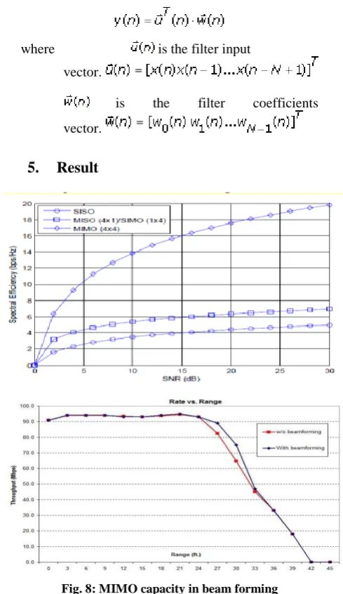
5.
Result
Fig. 8: MIMO capacity in beam forming
6.
Conclusion
7.
Future Enhancement
Multi-User Multiple-Input and Multiple-Output (MU-MIMO) is a second wave and major feature of recent 802.11ac standard. MU-MIMO builds on MIMO technology of 802.11ac and allows to group devices together. It allows to serve them simultaneously and to utilize the maximum amount of bandwidth available to those devices. This network gives the best possible speed with best network coverage and it is the most efficient network. It satisfies many needs in both endeavour and purchaser that finally make access point upgrade sensible.
Reference
[1] Xiaohu Ge, Ran Zi, Haichao Wang, Jingzhang and minho, Jo Multi-User Massive Mimo Communication Systems Based On Irregular Antenna Arrays, IEEE Transactions on Wireless Communications, Vol. 15, No. 8, August 2016, pp. 5287- 5301.
[2] Pierluigi Vito Amadori and Christos Masouros, Interference-Driven
Antenna Selection forMassive Multiuser Mimo, IEEE Transactions
on Vehicular Technology, Volume: 65, Issue: 8, Aug. 2016, pp. 5944 – 5958.
[3] Yue Gao, Runbo Ma, Yapeng Wang, Qianyun Zhang and Clive Parini, Stacked Patch Antenna with Dual-Polarization and Low Mutual Coupling For Massive Mimo, IEEE Transactions on Antennas and Propagation, Vol. 64, Isssue 10, October 2016, pp.1-10.
[4] Christoph Dahl and Ilona Rolfes, Mimo Radar Concepts Based On Antenna Arrayswith Fractal Boundaries, Radar Conference (EuRAD), European, 5-7 Oct. 2016.
[5] Xiangdong Jia1, Meng Zhou, Mangang Xie, Longxiang Yang and Hongbo Zhu, Optimal Design of Secrecy Massive MimoAmplify-and-forward Relaying Systems With Double-Resolution Adcs
Antenna Array, IEEE Access, Volume. 4, 29, November 2016, pp.
29 November 2016.
[6] C. Masouros And M. Matthaiou, ―Space-Constrained Massive Mimo:Hitting The Wall Of Favorable Propagation,‖ IEEE Commun. Lett., Vol. 19,No. 5, May 2015, pp. 771–774.
[7] J. Hoydis, S. Ten Brink, And M. Debbah, ―Massive Mimo: How Many Antennas Do We Need?‖, Proceedings of 49th Annu.
Allerton,IEEE Journal on Selected Areas in