Available Online at www.ijpret.com 420
INTERNATIONAL JOURNAL OF PURE AND
APPLIED RESEARCH IN ENGINEERING AND
TECHNOLOGY
A PATH FOR HORIZING YOUR INNOVATIVE WORK
CONTROLLER DESIGN FOR TORQUE CONTROL OF AC AND DC MOTOR
NEHA GANGRAJ, SANDEEP MAHAJAN
Power Electronics & Power System, GHRIETW, Nagpur
Accepted Date: 05/03/2015; Published Date: 01/05/2015
\
Abstract:This paper describes a controller design for Torque control of AC & DC motor. There are two methodologies used while designing the controller. In case of AC motor, the firing angle of the TRIAC is varied that provides control over its average voltage. While in case of DC motor the voltage at the motor terminal is directly varied. And the speed control is governed by the control over the average voltage. As, the voltage is directly proportional to the speed. Thus Both these method controls the speed of the motor. Controlling the average voltage in the circuit provides indirect control over its current. And since current is directly proportional to the torque. An Indirect torque control is carried out. The Whole hardware structure can be processed in a single central unit and can be termed as a Reconfigurable universal controller. Temperature sensors, Current sensors, Speed sensors etc can be included into the hardware as per the application requirement. Thus This controller also gives an intelligent motor control (IMC) operation. Visual Basic 6.0 is used for providing the Graphical user interface (GUI). The hardware can be connected with the computer/laptop through a serial port.
Keywords: Torque, Speed, RUC, GUI, Visual Basic 6.0, IMC.
Corresponding Author: MS. NEHA GANGRAJ
Access Online On:
www.ijpret.com
How to Cite This Article:
Available Online at www.ijpret.com 421
INTRODUCTION
THis paper explains a design of a controller that can provide Indirect torque control for the motors (AC & DC). While designing this controller few importance electrical relationships were taken into account. i.e. relations between voltage and current, Voltage and speed, Current and torque. The necessary mathematical equations for these relations will be discussed in further in the paper. Before that the basic operation and design of the motor is discussed in the paper.
Motors are considered as one of the most important part of an Industry. All the functions of the industries works on different types of motors. There are various types of motors being used in industry depending upon its application. But the very basic motors (AC & DC) will be discussed in the overall paper.
All the rotating electrical machines mainly consists of two important parts. They are a rotor and a stator. The rotor is the part of the machines that rotates and the stationary or the fixed part is the stator. The stator core is made up of many thin metal sheets called as laminations. Laminations are used for reducing the energy loss. The stator is mounted inside a frame like structure i.e. the Enclosure. The machine rotor part is inside the stator that can made free rotation when connected to the supply. The stator and the rotor are separated by an air-gap.
Machines are broadly classified into two main types:
1) AC machines
2) DC machines.
Induction motors (AC motors) that can be three phase or single phase are considered as constant speed motors. Since speed of theses motors depend on the supply frequency and the number of windings. Despite of having advantage over the DC motors use of AC motor was limited earlier. With the advent of semiconductor devices e.g. transistors, IGBT’s, GTO’s etc induction drives have been improved. Hence in industrial application AC motors are preferred over DC motors. But DC motor control is much easy than AC motors. Since DC machines has comparatively simple structure. Thus there is a need to design a controller that can provide control of the motor AC or DC.
I. torque – SPEED RELATIONSHIP
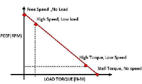
Available Online at www.ijpret.com 422 rotating machines. Speed is expressed as the shaft revolutions per minute or RPM. In drives applications, performance of the system is usually discussed in terms of speed, torque or other motor parameters that are applied to the shaft of the motor. Whereas torque is expressed as a force required to turn the motor shaft. Every motor has its own torque- speed curve.
Consider a motor with a constant input voltage. The speed of the motor in this case will be determined by the load on the motor shaft. Now, only way to increase the speed is by increasing the input voltage. And will increase the speed which will require some more torque to accelerate. But once the new speed is achieved, the torque will have to back off to its original value. Motors apply torque in response to mechanical loading. If there is no load on the motor, the motor will spin at a very fast rate. In real life this scenario is never seen. This is because of the reason that there is always a friction due to motor system , and it act as one of the load. And this will initiate the motor to output torque to overcome it. If the load at the output of the motor is higher, the motor will fight back with an opposing torque. The motor always outputs a fixed amount of power and thus slow down its rotational speed. If the motor load is increased, eventually the load overcomes the motion and it will stop spinning. This condition is known as STALL.
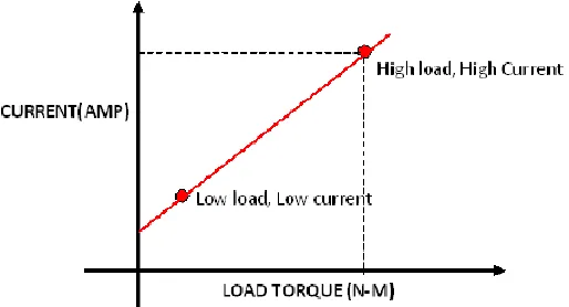
Depending upon the load at the motor output, the current will be drawn by the motor. Increase of the load, will tend to increase the torque at the motor terminal and hence the current. The current drawn by the motor is inversely proportional to the rotational speed. This is shown by the graph in figure 1.
Available Online at www.ijpret.com 423
Fig. 2 Graph Showing Relationship Between Load Torque and Current
From graphs we can easily conclude that speed is proportional to the voltage, similarly the torque is proportional to the current. Limiting the current can allow torque control of the motor[4].
Torque control of ac motor is much more complex than dc. As it has very complex parameters which includes voltage, current, frequency, etc. There exits a relationship between torque and current. The relation is given below.
T = K . I
Where T - Torque
I - Armature current.
K - Torque constant that depends on flux densities of fixed magnets.
Equations for DC motor:
Va = Ra Ia + La d/dt (Ia) + Ea
Ea = Kv * ω
Te = Tl = Kt * Ia
Equation for AC motor:
Te = (3 Ei . Is . cosᵞ)/ ωrm
Available Online at www.ijpret.com 424 Ei is also speed dependent ωrm.
II. METHODOLOGY
There are two methods used while designing the controller. For the control of AC motor the controller design involves control of firing angle of the TRIAC. And this can be done by sending control signals to the TRIAC using a microcontroller. This can also be well known as duty cycle control. The duty cycle can also be varied by varying T or f. Therefore the voltage can also be varied and thus power in the circuit can be controlled. As the time changes the width of the pulse is varied and this type of control is known as PULSE WIDTH MODULATION.
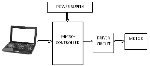
For DC motor control the average motor across the motor is directly controlled, this is done by using a simple voltage divider method. Different level of voltages will be set for the control of AC and DC motor. The current through the motor will be monitored and controlled i.e. indirectly controlling the torque. PWM technique not only controls the motor speed but also helps in reducing or cancelling the harmonics. This entire control circuit will be equipped in a single hardware structure and will therefore be termed as Reconfigurable Universal Controller.
Reconfigurable Universal Controller or Universal Motor Controller will involve two most important function of motor protection and motor management. The function of this device can be adjusted or extended over a wide range to cover the need of different industries.
Fig. 3 Overall Structure of Control Drive Circuit.
Available Online at www.ijpret.com 425
III. SOFTWARE
There are different software involved while designing the overall system. The list of the software is given below.
a. RIDE (Raisonance Integrated Development Environment) - For converting the code into
machine language that can be easily understood by the microcontroller. It is used for editing to compiling, linking, debugging and provide access to all development tools.
b. FLASH MAGIC - this software helps to dump the program opcodes to the microcontroller.
This allows easy access to all the ISP features by the device. I.e. programming the flash memory, Reading from flash memory.
c. PCB123 - This will help for designing the circuit on the printed circuit board.
d. VISUAL BASIC 6.0 – This software would provide a graphical user interface (GUI) between
machine and man it will be used for creating a graphical user interface for the application with the help of components available on the window. The application software to interface hardware system connected to PC using COM ports and provide GUI interface.
IV. CONCLUSION
Kron’s Primitive machine model provide a better platform in understanding the machine, and also the principle of all the rotating electrical machines. The controller deigned will be helpful for control of AC as well as DC machines. This controller can be easily interfaced along with the PC, such that different settings can be loaded based on the requirement.
PWM technique will be used in modulating the width of the pulse that will be given to the motor for its operation. This will provide solution to the power line problems in industrial environment. Therefore the reconfigurable drive system is universal in application for harmonic cancellation requirement.
ACKNOWLEDGMENT
Available Online at www.ijpret.com 426
REFERENCES
1. Dr. P. S. Bimbhra. Generalized theory of electrical machines, fifth edition. Pp . 1-30
2. Ashfaq Husain, Electric machines. Second edition.
3. Sushant Mahajan. Reconfigurble universal speed control based on Korn’s Primitive Model. IJERT. Vol-2 , Issue-12. December-2013.ISSN: 2278-0181
4. Shatori Meadows. Abin Ebrahim, Speed and Torque control of mechanically coupled permanent magnet direct current motor. ACEEE Int. J. on control system and instrumentation, Vol. NO. 2 June 2013
5. Parviz Amiri. Mahsa Bagheri. Speed control of DC motor by programmable control logic with high accuracy. Universal Journal of control and automation 1(4) : 91-97,3013
6. Suroor Moaid Dawood , Dr. Rabee Hashim Thejeel, PIC 16F877A Microcontroller based multiple DC motors controller. Asian Transcations on Engineering, Vol. 3, ISSUE- 2, ISSN: 2221- 4267.
7. R.Bayindir, S.Vadi, Real-time monitoring and control of the parameters of an induction motor, ELEKTRONIKA IR ELEKTROTECHNIKA, Vol. 19, No. 10, 2013,ISSN: 1392-1215.
8. Mane,shekhar, Khade, R.H., A Zigbee based wireless reconfigurable stepper motor controller using FPGA, UACEE International Journal of Advances in Electronics Engineering Volume 2: Issue 3 ISSN 2278 - 215X (Online), pp 130-133.
9. Parkhi, V., Shilaskar, S., Tirmare, M. and Jog, M. (2008) FPGA implementation of PWM control technique for three , phase induction motor drive’, IEEE Proc. of ICETET-2008, pp.996-1001
10. Chen, S. and Joos, G. (2002) ‘ Symmetrical SVPWM pattern generator using field