Abstract. In this paper we present a web-based distributed fault simulation framework built with standard Java Applet/Servlet technology and the popular platform independent open source database MySQL. Fault simulation plays an important role in digital electronics design flow by creating and evaluating test patterns, identifying and locating the causes of the circuit failures. Because of the rapid increase of the circuit sizes, there is ever growing need for memory and computational power. Our solution allows to seamlessly aggregate many remote computers for one application. We propose a novel collaboration centric computing approach using a participant credit based priority concept. Issues of task partitioning, task allocation, load balancing and model security are also handled. Our primary goal during circuit partitioning has been the decrease of the needed simulation memory to allow working with larger circuits for which conventional simulation methods are not always usable. Our novel method of partitioning produces model slices with no interdependences, suitable for Internet based use. Larger scalability is achieved by using model partitioning along the test pattern set partitioning.
Key words: distributed computing, collaborative computing, fault simulation, critical path tracing, digital test
1. Introduction. The complexity of today’s very large scale integrated (VLSI) circuits is still increasing according to Moore’s law, which states that transistor density on a chip doubles about every two years. This trend is predicted to continue at least for another decade. The International Technology Roadmap for Semi-conductors (ITRS) [1], an interesting assessment of the future technology requirements, states that number of logic gates in consumer level System-On-Chips (SoC) is 28 million at present and it is expected to increase 17 times by the year 2024. On the other hand, the number of test patterns required for high fault coverage of stuck-at-faults only, is at the moment about 30 thousand and is estimated to be 16 times higher respectively at the end of the roadmap.
The pattern count will increase as logic gate count increases. This fact influences both test development and test application times, and will be a major driver of overall development costs in the future. Automatic test pattern generation (ATPG) for structural test, design-for-testability (DFT) methods like random pattern logic built in self-test (BIST) and test pattern compaction are important techniques to reduce large amount of test data for logic cores [1]. Widely used procedure in these computation intensive test engineering tasks is fault simulation, which evaluates quality of the test patterns in terms of fault coverage. Within applications this intermediate step of the fault simulation usually needs to be carried out thousands of times, hence making simulation speed one of the key issues for overall task performance.
One solution for faster simulation, besides of improving fault analysis algorithms, would be to cooperate and combine available computing resources. We can assume that participants’ computers are not optimally loaded all the time. The work could be more effective when every participant had a chance to run his tasks using collective resources, especially when it is possible to parallelize the task execution. Parallelization technique is application specific, though.
In case of fault simulation, there are several possibilities: algorithm itself can be parallelized, circuit model can be partitioned into separate components and simulated concurrently, fault set and test pattern set can be divided and simulated in parallel. Fault parallelism [2] and pattern parallelism [3] are easy to implement (data set simply needs to be splited) and have shown relatively good performance. Combining both of them has been proved even more effective: easy-to-detect faults are identified first with fast preprocessing and simulated in parallel among processors, remaining faults are targeted by all processors, each using only subset of test vectors corresponding to its partition [4]. Circuit partitioning has got less attention, but it is useful when number of gates is as big as it is today– modern fault simulators require a lot of memory to be efficient. When simulation model does not fit into memory, performance is drastically reduced or simulation is not possible at all. Parallel fault simulation with circuit partitioning was used in [5,6] for vector-synchronous implementations on message passing multiprocessor systems. Circuit partitioning approach for shared memory systems was presented in [7]. The method presented in [8] distributes the component models of the circuit partitions to unique processors
∗This work was supported by Estonian SF grants 7068, 7483, EC FP7 IST project DIAMOND, ELIKO Development Centre
and European Union through the European Regional Development Fund (Research Centre CEBE).
†Tallinn University of Technology, Estonia ({ieero|serega|raiub}@pld.ttu.ee).
of a parallel processor system for concurrent and asynchronous execution. Partitioning issues are not handled here, however a manual partitioning was supported.
This paper presents a loosely coupled asynchronous Internet-based fault simulation approach, relying on model parallelism and test parallelism. Fault detectability computation model for the circuit and test pattern set are divided. Sub-sets of test are evaluated on partial computational models concurrently on different computers in wide or local area network. Our approach has no specific fault list as faults are already in the simulation model. During the model partitioning some overlapping is likely to occur as it is better to avoid interdependences, because of the communication penalties. These repetitive model parts are simulated several times. Results of fault simulation on partial models will be accumulated in overall fault coverage.
The concept of the current solution was initially inspired from MOSCITO framework [9,10] used for example in European VILAB cooperation project. The original system was implemented as client-server Java application. It allowed invoking single work tools remotely and organizing them into predefined automated workflows. Users in different locations cooperated via sharing their software tools in joint workflows. However, parallel execution was not supported. Moreover, the major limitation for widespread Internet based use was TCP/IP socket based communication schema that required opening dedicated communication ports in firewalls not only on server side, but also on the client side for each application and for end users.
A flexible web-based solution for remote tool usage following some key ideas of MOSCITO was proposed in [11]. The socket communication was replaced with HTTP, Java Servlets were used on server side and Applets along with Java applications were used on client side and also a database was introduced. In the current paper, this concept is revised and improved to support distributed computing and collaboration via effective resource sharing and load balancing.
There exist also several general purpose frameworks for distributed computing like BOINC [12], Globus [13], AliCE [14] and Condor [15] to name a few. Most popular seems BOINC (Berkeley Open Infrastructure for Network Computing), a non-commercial middleware system for volunteer computing, originally developed to support the SETI@home project, but intended to be useful for other applications in areas as diverse as mathematics, medicine, molecular biology, climatology, and astrophysics. The intent of BOINC is to make it possible for researchers to tap into the enormous processing power of personal computers around the world.
A major part of BOINC is the backend server. The server can be run on one or many machines to allow BOINC to be scalable for projects of any size. BOINC servers run on Linux based computers and use Apache, PHP, and MySQL as a basis for its web and database systems. Its framework uses cross-platform WxWidgets toolkit for building GUI-s. BOINC is a software that provides an infrastructure for distributed applications. It is capable to download of input data (work units), schedule of multiple BOINC projects on the same CPU, and provides a user interface to the integrated system. Scientific computations are run on participants’ computers and results are analyzed after they are uploaded from the user PC to a science investigator’s database and validated by the backend server. The validation process involves running all tasks on multiple contributor PCs and comparing the results.
The major drawback of the BOINC system is the use of remote procedure call (RPC) mechanisms which is often felt to be security risk, because they can be the route by which hackers can intrude upon targeted computers (even if it’s configured for connections from the same computer). The use of PHP over Java cannot be considered as an advantage.
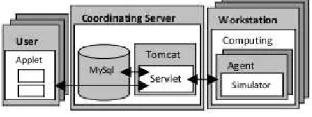
Fig. 2.1.System components and communication
formats and protocols.
AliCE, developed in National University of Singapore, attempted to become a grid development system instead of just being collection of grid tools. Similarly to Globus, AliCE core layer has components for resource management, discovery, and allocation, data management, monitoring and accounting, communication and security infrastructure. On top comes extensions layer consisting distributed shared memory programming templates, runtime support infra-structure, and advanced data services. The running system has consumer, producer and resource broker entities. The consumer submits the application code to the grid, the resource broker directs the application to appropriate task farm manager, which initiates the application and creates a pool of tasks. Task references are returned to the resource broker, which schedules the tasks for execution on producers. The results are returned to the consumer. Communication infrastructure supports the migration of codes, data and results via ”Space”– a special form of shared memory. Communication is carried out with objects. Objects and code are serialized and packed into jar archive fail – obviously in order to reduce the amount of transferred data. AliCE is based on Java Jini technology [21] and JavaSpaces [22]. Java Native Interface (JNI) is used to invoke non-Java code. The authors have used the system in several projects like [23], but it seems that activity around AliCE has lost its momentum at present. Technology itself is still promising. Only drawback in our point of view is that Jini technology is based on Remote Method Invocation (RMI)– although elegant programming solution for distributed computing, were one program can remotely invoke methods physically residing in other machine, however, firewall traversal can be problematic as dedicated communication ports are needed. Strict security policy might not allow that.
Condor is another project providing support to high-throughput computing, allowing users to take advantage of idle machines that they would not otherwise have access to. Condor is suitable for executing long running jobs that require no user interaction. Application source code must be recompiled with special libraries. Condor is useful to do task allocation and load balancing; it does not provide task decomposition however.
The rest of the paper is organized as follows: the overall concept of web-based infrastructure is described in section 2. In section 3 the priorities concept is explained. Task partitioning and task allocation are handled in sections 4 and 5. Section 6 considers the circuit model security. Section 7 presents workflow with distributed computing. Experimental results are presented in section 8 and conclusions are given in section 9.
2. Distributed environment. Our Web-based infrastructure is built on Java Applet/Servlet technology [24] and popular platform independent open source relational database MySQL [25]. The communication flow between system components and implementation details can be seen in Fig. 2.1. Servlet is a Java application that runs in a Web server or special application server and provides server side processing like different cal-culations, database access, e-commerce transactions, etc. Servlets are designed to handle HTTP requests and are the standard Java replacement for a variety of other methods, including CGI scripts, Active Server Pages (ASPs) and proprietary C/C++ plug-ins for specific Web servers (ISAPI). Because servlets are written in Java, they are portable between servers and operating systems. The servlet programming interface (Java Servlet API) is a standard part of the Java EE (Enterprise Edition of Java), the industry standard for enterprise Java computing. Tomcat [26] is open source servlet container (application server software) which is one way to run Java Servlets. Tomcat is developed by the Apache Software Foundation (ASF) and implements the Java Servlet and the JavaServer Pages (JSP) specifications from Sun Microsystems, and provides a pure Java HTTP web server environment to run a Java code.
2.1. Data management. The data handling takes place on coordinator node. The problem is that web-based HTTP communication is stateless and the session is valid for short time only, but the simulation process may run much longer. Therefore, the users must be identified; their tasks and results must be stored for later access.
The data module has three layers: presentation (user interface), business-logic (database queries, data processing) and physical database. First two layers are implemented in Java. The user is accessing database only via presentation layer, which consists of several functions to run middle layer queries. The database access is implemented according to Data Access Object (DAO) design practice. The data access objects manage access to relational databases. Each table in a relational database corresponds one Java class. The database table attributes map to Java class properties. For each property, there exist ”set” and ”get” methods. Additionally, DAO class has methods to insert, update and query the records in the database tables. For example, for table ”Tasks”, we will have at least properties like ”taskId”, ”userId” and ”status”; methods could be like ”getTaskId”, ”setStatus”, ”insertTask”, ”getCompletedTask”, etc. The standard Java mechanism for accessing databases is using Java Database Connectivity (JDBC) API. For convenience purposes, we have captured basic DB connection code into single DB access class and every specific DAO class, like ”TasksDAO” class, extends that class i.e. basic connection methods are inhereted and used inside the class.
Alternatively, it could be possible to use the popular Hibernate [27] and Spring [28] frameworks to simplify objects to relational DB mapping (ORM). For large and mission critical projects also Java EE technology like Enterprise JavaBeans is available [29]. However, for simple data persistency in current situation, the proposed solution is adequate and was faster to implement. Setting up and closing DB connections is time consuming operation, therefore we have used Tomcat’s native connection pooling to speed up DB transactions.
2.2. Communication. The use of applet/servlet approach implies that the general communication is based on HTTP protocol. The tools on different computers and on different computing platforms (UNIX, Linux, Windows) can easily exchange data as serialized Java objects. Data passing between components is implemented following Transfer Object (TO) design practice. A transfer object is a lightweight version of DAO object, it has only properties and ”get” and ”set” methods. Information is sent as data bundle as opposed to single strings.
HTTP protocol allows us also easy firewall traversal as we can use default web server port and Java servlet extensions on web servers as sort of proxies in order to reach intranet resources. There is no need for opening extra ports in the firewall on the user side as it is the case in TCP/IP socket based communication or when relying on Java RMI (which would be major restriction). Communication can be secured via SSL encryption by appropriate modifications in Tomcat configuration file, when necessary.
2.3. Tool encapsulation. Our simulator is implemented in C language, it has no graphical interface and network communication abilities. In order to integrate it into web based environment, it is necessary to implement additional software (Agent) layer. The simulator will be invoked from Java program (Agent), which allows to adapt the input data, convert the tool-specific data, retrieve the simulation results (log files, test vectors, etc.), map the control information to the embedded tool, transfer the status information (warning and error messages) to be submitted to the user, etc. The technically simplest way is to encapsulate the simulator as an entire program. Generally, integration of other work tools is possible similar way. Tool has to be able to run as a batch job. Also embedding of a library (e.g. C, C++ routines) via the Java Native Interface (JNI) is possible and also direct integration of Java-classes and applications (for Java software).
2.4. Graphical user interface. User interface (GUI) is based on Java Applet, which can be integrated into HTML page when needed. Java applets are very versatile in features and easy to develop. For rapid prototyping we have used NetBeans IDE [30], which supports visualized GUI development with drag and drop operations. Final tweaks to generated code still had to be done manually.
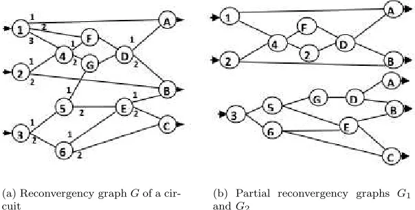
(a) Reconvergency graphGof a cir-cuit
(b) Partial reconvergency graphs G1
andG2
Fig. 4.1.Reconvergency graphs
the Applet. The user can contact Applet owner about authenticity of certificate, when neccessary. The Java Runtime Environment (JRE) is required to run the GUI Applet.
3. Priorities. One important prerequisite for collaborative computing is that performance of each par-ticipant is enhanced overall; nobody should experience unfair lack of the computing power, especially these participants who previously have donated the most of their resources. This implies we have to introduce a priority system based on each participant credit. The credit for host computer is calculated:
Credit=Credit+M ode·HostP erf·CompT ime·LoadF raction, (3.1)
where Mode equals ”1” when computer is donating and ”-1” when consuming;HostPerf referes to performance index of the computer, it is calculated initially after executing sample calibration task;CompTime is the time host computer has devoted to the current task; LoadFraction is number between 0 and 1, inclusively. Credit rating of the host increases while other participants are consuming its processor time, at the same time ratings of the quests will decrease the same amount. Credit numbers can go negative, it shows who is contributing and who is not. Participant with higher credit rating will have higher priority.
4. Task partitioning. Generally, there are several ways to parallelize the fault simulation: the algorithm can be parallelized, the circuit model can be partitioned into separate components and simulated in parallel, the fault set can be partitioned and simulated in parallel or the test pattern data can be partitioned. In this paper, we rely on model parallelism and test set parallelism, faults being included already in our simulation model.
Our method of fault simulation based on the parallel exact critical path tracing, together with the detailed method of model partitioning can be found in [31]. The simulation model is created by a special topological analysis of the circuit. Each reconvergent subnetwork of the circuit produces a sequence of computation formulas, and the nested reconvergent subnetworks produce nested computation formulas. The whole set of formulas created in the process of the topological analysis of the circuit composes the simulation model. This model allows carrying out fast efficient fault simulation of the circuit where the number of repeated computations is minimized. In [31] it is shown how to divide the process of fault simulation driven by the simulation model into a number of parallel sub-processes. For each sub-process, a partial simulation model is constructed. The creation of such a set of independent simulation models gives us the opportunity to use a distributed environment to achieve higher speed of fault analysis.
Fig. 4.2.Memory distribution between processing units
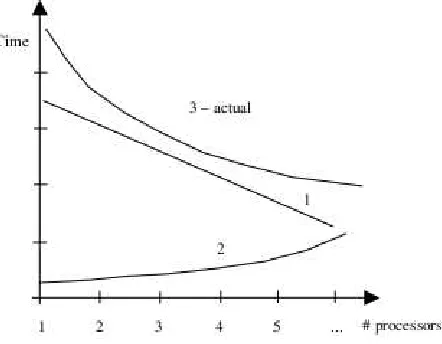
Fig. 4.3.Components of the simulation time cost
Fig. 4.1(b) shows a possible solution of dividing the reconvergency graph in Fig. 4.1(a) into two partially overlapped reconvergency graphs which allow creating two simulation models to be processed independently in parallel preserving all the advantages of parallel fault simulation by critical path tracing.
Fig. 4.2 illustrates the model partitioning. On the left, one processor case is depicted– all imaginary pieces one to five, are simulated subsequently. On the right, a multiprocessor case is depicted. We see the same model pieces distributed along processors. Largest model piece determines the actual simulation time, i.e. the time the user will have to wait. Also maximum reduction in memory requirement is determined by largest model piece (”1” in our example). Because of the overlapping, total amount of the memory used by simulation system will increase, but on a single computer required memory amount will decrease. It would be possible to find the optimal selection of partitions to minimize the sizes of overlapped areas. We have used randomized technique here. First we select nodes randomly into partitions, thereafter we count the number of the overlapping nodes. Then we generate a new partitioning and evaluate the number of overlapping nodes again. On each iteration, we keep the best solution. The number of iterations is a function of the number of primary inputs of the circuits. On the Fig. 4.3, there is abstractly shown how actual simulation time is influenced by nonlinearity of component 2– time increases due to calculation model pieces overlapping. Component 1 would be the ideal simulation time.
Let’s assume we have the system depicted in Fig. 2.1. There is one central Coordinating Server, several users and several simulation Agents. The work of Agents is controlled by a Coordinator instance running on the Server as a Servlet. Initially, idle simulation Agents are polling the Coordinating Server. Each Agent announces its allowable load threshold, its current load and current performance index. Performance indexes are determined by host profiling i.e. Agents execute a small sample task and measure the completion time. Thereafter, Agents prepare their profiling messages for the Coordinator. These messages include also time stamps, so the Coordinator can measure the transfer time and determine network latency indexes for different Agents (it is assumed that clocks of the hosts are synchronized). The Coordinator collects the information initially for some predetermined time, obtained coefficients are applied later– faster machines will get larger tasks respectively.
Let’s assume now that tasks are already submitted to the Coordinator. The scheduler takes the task with highest credit rating and selects an Agent with least load index in the list, given that agent’s load is smaller than allowed threshold. Thereafter, the scheduler takes the task with next highest credit rating and searches for next Agent satisfying the threshold condition above. This repetitive process continues until there are no tasks in the list. The Agent selection idea in this intuitive scheduling strategy corresponds to Best-fit algorithm described in [33] and used for memory allocation problem.
When a higher-priority task is submitted to scheduler, and there is no idle Agent available in the system, then the scheduler has to suspend or reallocate some of the current tasks if expected completion time of the priority task is greater than migration time of the current task. The candidate task for migration is the one who has the lowest priority and longest execution time. Migration means that Agent notifies the Coordinator and sends intermediate result of simulator tool to the Coordinator and thereafter the Agent terminates the simulation task. The scheduler finds new target candidate for the task under migration– it will be the Agent with the lowest credit rating and with the best performance rating.
The task must be also migrated when the load on the host increases above allowable threshold, i.e. if the local computing activity increases, as our goal was that participants in collaboration may not suffer. Exception is the case when such task belongs to the host owner. The load threshold is adjustable by each participant. Further information on load balancing can be found for example in [34,35,15].
6. Circuit model security. In this paper, we assume that the server host is trusted– circuit models must be uploaded first. Other hosts of participants can be less trusted, because to a certain extent, we can overcome the model security problem automatically by partitioning the model itself– partial model is not very valuable for potential malicious agent. We may even enforce that model pieces are scheduled to the same processors during repetitive executions of the same circuit model, disabling the potential collection activity. However, identifying the right pieces of model must be handled. It is possible to compute the hash value of the model piece and save it to database. When later within limited time frame same hash value is computed for some model piece, then this task is scheduled to the same processing unit. Less limiting strategy is to ensure that not all the model pieces will be scheduled to the same processing unit. Malicious collector still will have no complete puzzle. Let us note that it is much harder to assemble the meaningful full model from pieces than just to recognize the same model piece. Computation of hash values could be performed in parallel with separate execution threads on multiprocessor computer.
Table 8.1
Distributed simulation results.
Circuit B17 B18 B21 B22 Max model partitions 13 8 12 13
Max model build, s 0.24 1.83 0.32 0.37 Max subtask simul,s 214 1534 146 195 Subtask simul dev, % 21.0 24.4 15.7 5.5 Model size reduction 4.1 2.8 2.5 2.6 Speedup by model part. 3.2 6.4 2.5 2.9 Speedup by test part. 10.3 7.9 8.7 10
The simulator first constructs simulation model taking into account of the size limit of the subtask. While reaching the limit, it saves the breakpoint information into local file system. The simulation Agent then reads the breakpoint information and passes it to the Server where it will be stored for other simulation agents. When the next idle Agent is polling, then it will receive the circuit file along parameters and breakpoint information. The Agent starts a new copy of simulator tool on the other computer. The simulator first constructs the simulation model again, but this time it is not starting from beginning, but restores from the breakpoint up to the point when task size limit will be reached. New break point information will be again saved to local file system and later passed to the Server database by the Agent. The simulator Agents then wait until their subtasks will be completed and report results back to the Coordinator.
The process repeats until there are no simulation sub tasks left. Note that simulators have been started subsequently, but thereafter they run concurrently. Total starting delay is small compared to runtime. Finishing order of simulation sub-tasks is not pre-determined as simulation speed depends on the piece of the circuit model– some pieces are more complicated to simulate and need more time.
When all simulators are finished, then the Coordinator assembles sub results into final result and stores in the database. Results are passed to user when requested.
8. Experimental results. In experiments we measured communication overhead, memory reduction by circuit partitioning, simulation speedup and scalability with current task partitioning when number of processing units increases. Simulation was carried out on UltraSPARC IV+ 1500Mhz servers. Tomcat servlet engine and MySQL database were running on two core AMD Athlon 64 6000+ 3 GHz processor with 2 Gb memory. User applet was also running on the similar Athlon machine. Experiments show, that on the user computer circuit file loading takes about second for the over 3 Mb size circuit files depending on computer’s performance. File transfer to the database and user notification takes about 6 seconds. Thereafter, simulation agent receives circuit file from the Coordinator 3-4 seconds later. Total communication delay was 12-15 seconds in case of distributed web-based solution. The total communication overhead was about 1% compared to single processor solution in the case of largest circuits. The overhead depends on the size of the circuit and the number of test vectors simulated.
Simulation results for sample circuits [36] are presented in Table 8.1. 100K test patterns were applied to each circuit. We can see that model build time for subtask (circuit slice) is very small (0,1% for b18 circuit) compared to simulation time.
Final simulation time is dominated by the longest subtask simulation time. We see that there is some deviation from ideal mean time. This implies that model partitioning could be still improved– model slices could be more balanced in size. This would lead to more equal and shorter simulation times and user would get final result faster. However, the possibilities of balancing the partitioning of the model depend essentially on the circuit structure.
The last rows of Table 8.1 present simulation speed-up for the simulation distributed on several processors compared to single processor local simulation. Scalability in case of model partitioning is degrading due to model pieces overlapping. For the purpose of fair comparison, the speedup results in rows 6 and 7 are calculated for the same number of partitions (first row in Table 8.1) for both types of partitioning.
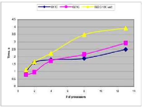
Fig. 8.1.Simulation of 100K vectors
Fig. 8.2.Total model build time
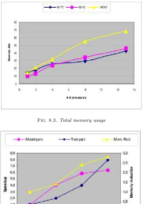
are used. Figure 8.4 illustrates results for largest (104580 logic gates) B18 circuit. Model partitioning speedup is quite close to test partitioning speedup. Initially, up to 6 processors model partitioning has an advantage compared to test partitioning. On the same figure, also a rather linear reduction in memory requirements is depicted.
9. Conclusion. We have presented how distributed computing paradigm can be used collaboratively in the field of digital fault simulation. In contrast to existing solutions, we have developed a novel Internet based loosely coupled system, which allows seamlessly aggregate computers of dislocated working groups into one powerful simulation application. We have introduced a credit based priority management method, addressed task scheduling and task partitioning problems, handled model security. Our primary goal during task parti-tioning has been the decrease of circuit simulation memory requirement. Generally, there are three ways to achieve this goal: parallelizing circuit model, dividing test set and partitioning the fault set. In case of our solution, simulation model, derived from circuit model, contains already fault information. Therefore, we are partitioning only simulation model and test set. In contrast to previous parallel simulation solutions we have introduced a circuit partitioning method that is suitable to be used in systems with communication delays like the Internet based distributed simulation environment, as our partitioning method will produce model slices with no interdependences.
Fig. 8.3.Total memory usage
Fig. 8.4.Circuit B18 experimental results
case of the circuit B17, for example. Model partitioning is also useful in sense that it offers basic circuit model security since entire model needs to be handed over to central server only. The server however can be well secured.
In experiments, the total communication delay for end user was approximately 12-15 seconds in average compared to local single processor solution. The communication overhead depends on the size of the circuit and the number of test vectors simulated. In practice, circuits and vector sets are much larger - the overhead would be consequently smaller. The proposed collaborative computing approach allows to solve larger fault simulation problems which otherwise would be difficult to achieve due to memory and time constraints with conventional simulation approach. Combining model partitioning with test partitioning allows achieving a better scalability. Model partitioning algorithm could be possibly improved in the future to support finer granularity. However, combined with test set partitioning, it is already sufficient for moderately sized collaborative consortium, since in reality there is usually more than single circuit model in use at given time, consequently total number of tasks to be scheduled may be larger and appropriate for total number of computers available. In the future also tradeoff estimation between model partitioning and test set partitioning could be introduced. Design pattern proposed in current paper can be easily used for other distributed applications, only task partitioning is specific.
REFERENCES
Proc. 28th ACM/IEEE Design Automation Conf., San Fransisco, CA, 1991.
[8] S. Ghosh,NODIFS: A noval, distributed circuit partitioning based algorithm for fault simulation of combinational and sequen-tial digital designs on loosely coupled parallel processors, LEMS, Division of Engineering, Brown University, Providence, RI, Tech. Rep., 1991.
[9] MOSCITO, http://www.eas.iis.fhg.de/solutions/moscito
[10] A. Schneider et. al.Internet-based Collaborative Test Generation with MOSCITO, in Proc. DATE02, Paris, France, March 4-8, 2002, pp.221–226.
[11] E. Ivask, J. Raik, R. Ubar, A. Schneider,WEB-Based Environment: Remote Use of Digital Electronics Test Tools, In Virtual Enterprises and Collaborative Networks, Kluwer Academic Publishers, 2004, pp. 435–442.
[12] BOINC, http://boinc.berkeley.edu/
[13] Ian Foster,Globus Toolkit Version 4: Software for Service-Oriented Systems, Journal of Computer Science and Technol-ogy,vol. 21, no.4, Jul. 2006, pp. 513–520.
[14] Y.M. Teo and X. B. Wang,AliCE: A Scalable Runtime Infrastructure for High Performance Grid Computing, in Proc. IFIP Int. Conf. Network and Parallel Computing, Springer-Verlag Lecture notes in Computer Science, Wuhan, China, October 2004.
[15] Condor, http://www.cs.wisc.edu/condor/
[16] D. Booth, H. Haas, F. McCabe et. al., Web Services Architecture, W3C Working Group Note, 2004. http://www.w3.org/TR/ws-arch/
[17] Simple Object Access Protocol (SOAP), http://www.w3.org/TR/soap/ [18] TeraGrid, http://www.teragrid.org/about/
[19] Open Science Grid, http://www.opensciencegrid.org/
[20] Large Hadron Collider (LHC) Computing Grid, http://public.web.cern.ch/public/en/lhc/Computing-en.html [21] Java Jini Technology, http://www.jini.org/wiki/
[22] JavaSpaces, http://www.jini.org/wiki/JavaSpaces Specification
[23] Y.M. Teo, S.C. Low, S.C.Tay, J.P. Gozali,Distributed Geo-rectification of Satellite Images using Grid Computing, In International Parallel and Distributed Processing Symposium, IEEE Computer Society, Washington, 2003.
[24] Java Servlet Technology, http://java.sun.com/products/servlet/overview.html [25] Open source database MySQL, http://www.mysql.com/why-mysql/
[26] Apache Tomcat, http://tomcat.apache.org/
[27] C. Bauer and G. King,Hibernate in Action, Manning Publications, 2004 [28] C. Walls,Spring in Action, Third Edition. Manning Publications, 2011.
[29] D. Panda, R. Rahman and D. Lane,EJB 3 in Action. Manning Publications, First Edition, 2007. [30] NetBeans IDE, http://netbeans.org/features/
[31] Devadze, R. Ubar, J. Raik, A. Jutman,Parallel Exact Critical Path Tracing Fault Simulation with Reduced Memory Requirements, DTIS09
[32] K. Hwang and Z. Xu,Scalable Parallel Computing: Technology, Architecture, Programming, McGraw-Hill, San Francisco, 1998.
[33] D. E. Knuth.Fundamental algorithms. Vol 1. Second edition. Addison-Wesly, 1973
[34] D.L Eager, E. D. Lazowska, Zahorjan.Adaptive load sharing in homogenious distributed systems, IEEE Transactions on Software Engineering, SE-12(5:662–675), May 1986
[35] N. G. Shivaratri, P. Krueger, M. Singhal,Load distributing for locally distributed systems. IEEE Computer 25 (12), December 1992.
[36] Example circuits, http://www.cad.polito.it/tools/itc99.html
Edited by: Dana Petcu and Alex Galis Received: March 1, 2011