ENG470 Honours Engineering Thesis (2017)
Photovoltaic Module and System Fault Analysis
Perth, Western Australia
A thesis project submitted to Murdoch University School of
Engineering and Information Technology to fulfil the requirements
for the degree of Honour Bachelor of Engineering in the discipline of
Instrumentation and Control Engineering and Renewable Energy
Engineering.
Author:
Salim Al Senani
Author’s Declaration
I declare that this thesis is my own account of my research and contains as its signficant content work which has not previously been submitted for a degree at any tertiary education institution.
Name: ……….
iii
Abstract
v
Acknowledgements
Firstly, I would like to acknowledge my thesis supervisor Dr. Martina Calais for her support throughout my degree, guidance, and her valuable time spent in order to assist me throughout this project. I would like also to thank the academic staff at Murdoch University those who had supported me through my entire honour degree programme and my thesis project specially
Professor Parisa Arabzadeh Bahri. Associate Professor Graeme Cole. Dr. David Parlevliet.
Mr Simon Glenister.
ix
Table of Contents
Abstract ... iii
Acknowledgements ... v
List of Figures ... xiii
List of Tables ... xv
List of Abbreviations ... xvi
List of Definitions ... xvii
1. Chapter 1 - Introduction ... 1
1.1 Background ... 1
1.1.1 Previous Work on The Original Version of the PVFRP ... 7
1.2 Description of the Project ... 8
1.3 Aim of the Project ... 9
1.4 Significance of the Project ... 9
1.5 Project Thesis Outline ... 9
2. Chapter 2 - Literature Review ... 10
2.1 Introduction ... 10
2.2 Previous Data Collections Groups on PV System Faults and Issues ... 11
2.2.1 Group 1: Expert Data Acquisition ... 11
2.2.2 Group 2: Voluntary Reporting ... 19
2.3 Developed Operational Faults in PV Systems ... 21
x
2.3.2 Inverter ... 27
2.3.3 Installation... 27
2.3.4 Other Failures... 28
2.4 Climate Zone in Australia ... 29
3. Chapter 3 - Methodology ... 31
3.1 Survey Methodology ... 31
3.1.1 Introduction ... 31
3.1.2 The Original Version of the PV Module and System Fault Reporting Portal ... 32
3.1.3 The Revised Version of The PV Module and System Fault Reporting Portal .. 35
3.2 Thesis Methodology ... 36
4. Chapter 4 - The Result and Evaluation of the Original Version of PVFRP ... 39
4.1 Introduction ... 39
4.2 General Findings ... 39
4.3 PV Module Section ... 42
4.3.1 Module Failure Types ... 42
4.3.2 Module Certification and/or Labelling Issues... 43
4.4 Inverters ... 44
4.5 Other Equipment ... 46
4.6 Installation Issues ... 47
5. Chapter 5 - The Result and Evaluation of the Revised Version of PVFRP ... 50
xi
5.2 General Findings ... 50
5.3 PV Module Section ... 54
5.3.1 Module Failure Types ... 54
5.3.2 Module Certification and/or Labelling Issues... 55
5.4 Inverters ... 56
5.5 Other Equipment ... 57
5.6 Installation Issues ... 58
6. Chapter 6 - Conclusion and Future Work ... 61
6.1 Conclusion ... 61
6.2 Future Work ... 62
7. Appendix ... 64
7.1 Description and General Details ... 64
7.2 PV Module Associated Faults ... 69
7.2.1 Glass Breakage Problem ... 70
7.2.2 Other Module Problems ... 72
7.2.3 Module Certification Issues ... 73
7.3 Inverter Associated Faults ... 74
7.3.1 Inverter Partial Failure ... 75
7.3.2 Other Inverter Problems ... 77
7.4 Other Equipment ... 79
xii
7.5 General Issues ... 83
7.5 The Survey Completion ... 85
xiii
List of Figures
Figure 1: The top 10 leading countries with cumulative installed a solar photovoltaic capacity
at the end of 2016 ... 3
Figure 2: Evolution of PV Installations (GW-DC) ... 4
Figure 3: PVFRP Survey Faults by Type ... 8
Figure 4: Result of Bypass Diode Testing for 1272 180 Wp PV Modules of a Single Type (Köntges et al. 2014) ... 15
Figure 5: Junction Box Failures ... 26
Figure 6:The Key Climate Groups Based on a Modified Köppen Classification System . ... 29
Figure 7: The Original Version of PVFRP Methodology ... 34
Figure 8: Thesis Methodology ... 38
Figure 9: Respondents by Types ... 39
Figure 10: PV Systems by Locations ... 40
Figure 11: Systems by Size ... 41
Figure 12: Systems by Type ... 41
Figure 13: Distribution of Different Fault Reports ... 42
Figure 14:Module Failure Types ... 43
Figure 15 Inverter Failure Types ... 45
Figure 16: Installation Issues Types ... 48
Figure 17: Respondents by Types ... 51
Figure 18: PV Systems by Locations ... 52
Figure 19: Systems by Size ... 53
Figure 20: System by Types ... 53
Figure 21: Distribution of Different Fault Reports ... 54
xiv
Figure 23 Inverter Failure Types ... 57
Figure 24: Installation Issues Types ... 59
Figure 25: PVFRP Survey - First Page ... 65
Figure 26: Revised Version of PVFRP Survey - Overview ... 66
Figure 27: PVFRP Survey - Personal Details and System Description ... 67
Figure 28: PVFRP Survey - System Description ... 68
Figure 29: PVFRP Survey- Fault Sections ... 69
Figure 30: PVFRP Survey - Module problems ... 70
Figure 31: PVFRP Survey - Glass Breakage Problem Period ... 71
Figure 32: PVFRP Survey - Glass Breakage versus System performance (%) ... 71
Figure 33: PVFRP Survey - Glass Breakage Problem Duration ... 72
Figure 34: PVFRP Survey - Identify Other Module Problems ... 73
Figure 35: PVFRP Survey - Module Certification Issue ... 74
Figure 36: PVFRP Survey - Module Certification Issues List ... 74
Figure 37: PVFRP Survey - Type of Inverter Problem ... 75
Figure 38: PVFRP Survey - Inverter Problem versus Performance ... 75
Figure 39: PVFRP Survey - Inverter Problem versus Performance (%) ... 76
Figure 40: PVFRP Survey - Inverter Problem Duration ... 77
Figure 41: PVFRP Survey - Identify Another Inverter Problem ... 78
Figure 42: PVFRP Survey - Choice of Report... 79
Figure 43: PVFRP Survey - Other Equipment Issue ... 80
Figure 44: PVFRP Survey - Other Equipment Issues Duration and Performance (%) ... 80
Figure 45: PVFRP Survey - Choice of Report After Attend Other Equipment Section... 81
Figure 46: PVFRP Survey - Installation Issue ... 82
xv
Figure 48: PVFRP Survey - General Issue ... 84
Figure 49: PVFRP Survey - Additional Reporting ... 84
Figure 50: PVFRP Survey - Additional Reporting Details ... 85
Figure 51: PVFRP Survey - Submit the Survey ... 85
List of Tables
Table 1: Certification Issues of PV Modules ... 44Table 2: Inverter Failure Types ... 45
Table 3: Other Equipment Issues ... 46
Table 4: Installation Issues Types ... 47
Table 5: Certification Issues of PV Modules ... 56
Table 6: Inverter Failure Types ... 57
xvi
List of Abbreviations
APVI Australian PV Institute
ARENA Australian Renewable Energy Agency
CEC Clean Energy Council
EVA Ethylene vinyl acetate
IEA PVPS International Energy Agency Photovoltaic Power Systems Programme
IEC International Electro technical Commission IITB Indian Institute of Technology Bombay.
NCPRE National Centre for Photovoltaic Research and Education
NISE National Institute of Solar Energy
PID Potential induced degradation
PV Photovoltaic
PVFRP Photovoltaic Module and System Fault Reporting Portal
WP Watt peak capacity, or nominal power, or the nameplate capacity
xvii
List of Definitions
In this research, several terms with the following definitions or short explanations are used.
All India Survey of Photovoltaic Module Degradation in India performed by the National Centre for Photovoltaic Research and Education (NCPRE) twice:
1. The first time in 2013 (Dubey et al. 2014). 2. Repeated in 2014 (Chattopadhyay et al. 2015).
The primary objectives of these two surveys were to assess the effect of climatic zones on the PV modules while considering the age of the PV systems.
Cell cracks are splits or cracks in the silicon wafer of the PV cells that regularly cannot be observed by the naked eye.
International Energy Agency Photovoltaic Power Systems Programme (IEA PVPS ) Task 13 is an international programme and partners of this programme were from 18 different countries. This programme focuses on developing the reliability of photovoltaic systems as well as the subsystems by gathering, analysing, publishing the data on their technical performance as well as failures and providing a basis for their assessment has a group of studies investigating include the following two published reports:
1. (Köntges et al. 2014) “Review of Failures of Photovoltaic Modules”.
2. (Köntges et al. 2017) “Assessment of Photovoltaic Module Failures in the Field”.
xviii
Power loss determination (definition) is done in different ways. The participants in the surveys usually estimate the power loss with respect to the nameplate power rating. This method is considered as one of the market’s accepted methods which are usually used for the manufacturer’s warranty purpose. Sometimes the initial power of Photovoltaic modules is available. In this situation, one can clarify the power loss relative to the initial measurement (the scientific approach).
Project Participants of Photovoltaic Module and System Fault Reporting Portal (PVFRP) which funded by the Australian Renewable Energy Agency (ARENA) are the Clean Energy Council (CEC), the Australian PV Institute (APVI), UNSW, and Ekistica.
PV specialists (experts) are manufactures, inspectors, auditors, and technical staff from research organisation.
PV non-specialists are installers, distributors, system owners and end users of PV system.
Quick connector is an essential element for the reliable power generation as well as the safety of the system. It is used to connect solar modules to each other, to extension cables, combiner boxes, to fuse boxes, and to the inverter
Unscheduled maintenance is maintenance due to a failure that develops during the operation of the PV system
Nominal service lifeand thetechnical lifetimeof PV module are terms used to describe the estimated period of operation of a PV module which is expected to be between 20 to 25 years.
1
1.
Chapter 1 - Introduction
1.1
Background
With the depletion of fossil fuel-based energy resources, globally, there is an urgent need to find alternative resources. The investments and subsequent studies in the field of renewable energy such as solar, thermal and wind started during the oil crises in the 1970s (Laird and Stefes 2009), but the high cost associated with the renewable energy technologies thwarted the widescale realisation of these technologies. The advent of more cost-effective technologies coupled with sustained higher oil prices in the last decade, for example, fuelled a rapid growth in this field. Governments in different countries support renewable energy in the form of tax breaks or subsidies, which in turn further reduce the retail price of renewable energy products such as solar panels. Renewable energy sources are easily available almost everywhere on this planet, environmentally safe, and highly sustainable. However, investment in renewable energy increasingly faces some challenges, which include the initial high cost (installation plus the components’ costs), a utility of power and its round-the-clock availability. Standalone systems need storage facilities, which makes them very expensive systems. The other challenge is the fluctuation of the generated power, for example, when the sky is fully cloudy, there will not be any power produced by the solar panels, and wind turbine will not produce power in the absence of sufficient wind. Moreover, there is an added uncertainty associated with these systems as no one can accurately predict the climatic condition which affects the power generation (PVPS 2016).
Despite these challenges, the future depends on developing reliable alternative energy sources and solar has the greatest potential.
2
especially in China, America and India. This contributes to the total cost reduction of PV installation and increases the total solar capacity in the world. By the end of 2016, around 75 gigawatts (GW) of PV capacity was installed world widely. The 25 International Energy Agency Photovoltaic Power Systems (IEA PVPS) countries installed a total of 265 GW of cumulative PV installations and other countries installed at least 35.7 additional GW(Fig2x). Therefore, the global total installed PV solar capacity was at least 303 GW (Jäger-Waldau 2017).
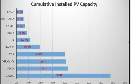
Figure 1 shows that the top 10 leading countries with cumulative installed solar photovoltaic capacity at the end of 2016: China (78,0 GW) is the top country, followed by Japan (42,8 GW), followed by Germany (41,2 GW) and then the USA (40,3 GW).
3
At the end of 2016, the 25 International Energy Agency Photovoltaic Power Systems Programmes (IEA PVPS) countries represented 265 GW of cumulative PV installations together, mostly grid-connected. Additional countries that are not part of the PVPS programme represent at least additional 35,7 GW, mostly in Europe; the UK with 11,6 GW, The Czech Republic with 2,1 GW (stable in 2016), Greece with 2,6 GW (stable in 2016), Romania with 1,3 GW and Bulgaria with 1 GW (stable in 2016). Following these countries, India has installed more than 9 GW and Taiwan more than 1 GW. Many other countries have installed PV systems but none have reached the GW scale. While other countries around the world have reached various PV installation levels, the total of these remains hard to quantify with certainty. At present, it appears that 298,6 GW represents the minimum installed by end 2016 with a firm level of certainty. Remaining installations account for some additional 4,5 GW installed in the rest of world (non-reporting countries, and off-grid installations) that could bring the overall
4
installed capacity to around 303,1 GW in total. Today, PV drive at least 0.1% of total international electricity generation (Jäger-Waldau 2017).
Despite the growth and the development of high quality, reliable solar energy, a high number of low-cost and low-quality PV modules has been entering the Australia market since 2008. There are process approval procedures, installation guidelines and standards which are made to protect the quality of the services and products. Despite this, there are PV installations and system components that are suboptimal. Consequently, these issues could lead to production lost or additional cost due to maintenance and subsequently could also long-term degradation lead to safety issues and fire hazards. For these reasons, different studies were attained in relation to the PV system reliability and fault analysis, for example, the Photovoltaic (PV) Module and System Fault Reporting Portal (PVFRP).
PVFRP is an online survey questionnaire (operating since 2014) designed to gather localised failure information of PV systems for different climate zones in Australia. This questionnaire is an activity run by the School of Engineering and Information Technology at Murdoch
5
University. PVFRP has been established as part of the project ‘Data Collation & Analysis for Development of a Climate-based PV Module Rating Scheme’. PVFRP was funded by the Australian Renewable Energy Agency (ARENA). This survey is supported by the Clean Energy Council (CEC), the Australian PV Institute (APVI), UNSW, and Ekistica (Project Participants). This project contributed to international PV Module Quality Assurance Task Force and International Energy Agency Photovoltaic Power Systems Programme (IEA PVPS ) Task 13. IEA PVPS Task 13 is explained in section 2.2.2. PVFRP can be accessed through Clean Energy Council (CEC) and the Australian PV Institute (APVI) webpages. PVFRP is intended to collect information from PV non-specialists (e.g. end users of PV systems, installers, and distributors) and PV specialists (e.g. inspectors, auditors, technical staff from research organisations, and manufacturers). The PVFRP is mainly aimed at gathering data about which section of a PV system has a fault, and further details about the defective equipment which mainly based on visual inspection only. The PVFRP is also aimed at gathering data from warranty returns (data) form module manufacturers. The survey covers five main sections: Module, Installation, Inverter, Other Equipment and General Issues. However, the respondent can add any additional comments before completing the survey. The obtained data will help with identifying issues with PV systems and assist in avoiding these in the future, enhancing solar system design, solar production, and components selection. The original version of PVFRP had operated from April 2014 until October 2017. The original version of the PVFRP, in operation for 41 months, is generally simple to access for respondents around the world. However, during the operation of the original version of PVFRP, it came apparent that there are issues and shortcomings include:
6
of the survey even though if the user needs to report only a failure under one section only as can be seen in Figure 7.
Many respondents did not provide the location of installation of PV system and essential system descriptions (e.g. the PV array capacity (kW), and postcode) because of these details are not compulsory. Consequently, it makes hard to analyse the data in relation to location or temperature zone.
For these reasons, a revised version was considered in order to improve this specific web-based survey. These changes are essential to satisfy the needs of respondents by simplifying their experience of the PVFRP and make the survey shorter. These changes are aimed to make it easier for the respondent to attempt the PVFRP questionnaire; however, the content of the survey questions has kept the same as explained in the next section (2.3).
There was a process that needs to be followed to approve the revised version by the Murdoch University Human Research Ethics Committee, and the Project Participants mentioned earlier.
The steps of this approval process involve:
The revision of the original survey and the development of the new survey. Approval from the Project Participants.
Refinement based on feedback.
Approval by the Murdoch University Human Research Ethics Committee. Documentation and assistance with launching the new survey.
7
details about the data collection of both versions are described in section 3.2. This thesis project is related to assess collected data from both versions of the PVFRP.
1.1.1
Previous Work on The Original Version of the PVFRP
The following brief description summarises two theses and two reports that illustrate the primary findings from Website (PVFRP):
1. A report by Zaman et al. (2014) illustrates the major findings from the PVFRP up to 2014. They compared results of the PVFRP with similar studies. The report also shows background information about the PVFRP project, its aims and development.
2. The thesis by Mahajan (2014) analysed and compared thePVFRP data with All Indian Survey (2013). All Indian Survey (2013) is described in section 2.2.1. Mahajan analysed the data in different climate zones including environmental conditions on the operation, and reliability of the PV systems and the paper states that failures in inverters dominate the reported failures in the PVFRP.
3. A report by Zaman, Parlevliet, and Calais ( 2014) illustrates the main findings from the PVFRP up to February 2015.They analysed PVFRP data, and the findings are filtered and expressed graphically and/or through tables which can be used for publishing or statistical purposes.
8
Overall, the results from these four papers show that the module faults, inverter faults and installation faults are considered the highest number of the reported faults compared to other reported failures and can be seen in Figure 3.
Figure 3: PVFRP Survey Faults by Type (Zaman, Parlevliet, and Calais 2015)
1.2
Description of the Project
9
1.3
Aim of the Project
The overall aim of this thesis project is to investigate the different failure types that are developed in PV systems (during the operation). Some of those failures could start developing before installation (through manufacturing processes or transportation).
The main purpose of the thesis project is to analyses the system faults obtained mainly from an electronic survey which is called the PV module and System Fault Reporting Portal (PVFRP). An essential aim of this project is also to contribute to the development and improvement of the PVFRP, and compare the revised version findings versus the original version findings. Another significant main aim of this project is to compare the findings from the PVFRP with literature review findings of similar reports, electronic websites, surveys, and other scientific papers. In addition, the thesis focuses on assessing the survey results of the PV system according to climate zones or system different locations. This is only possible if a certain amount of survey responders were collected.
1.4
Significance of the Project
There is an interest among stakeholders, include PV system organisations, research institutes, and consumers to provide a study of the developed faults in the PV systems in order to improve the future designs for such systems. There will be a review of current literature in the following chapter. This research aims to design a study that highlights the most common operational faults in PV systems in Australia.
1.5
Project Thesis Outline
This thesis is structured into six chapters. The contents of each chapter are described as follows:
10
Chapter 2 provides the literature review on the thesis topic.
Chapter 3 describes the method of data collections in the original and revised versions of PVFRP as well as thesis methodology.
Chapter 4 provides the evaluation of the original version of PVFRP. It is also discussed compare the main finding with those obtained by other authors. Chapter 5 provides the evaluation of the revised version of PVFRP. It is also
discussed compare the main finding with those obtained by other authors. Chapter 6 provide the conclusion and suggest some recommendations for future
work which can be done in order to improve the PVFRP.
2.
Chapter 2 - Literature Review
2.1
Introduction
11
performance of PV system, PV system components need to be examined. Fortunately, there are some maintained PV solar systems which have been in the field for more than 20 years. Those systems allowed (other) researchers to obtain a limited evaluation of the PV systems performance during the operation of the PV system. Many of these studies include identification of failure mechanisms, estimation of the system lifetime and predict the degradation rate. Clearly, study of the faults that are developed during the PV operation will assist to improve the future design (Kurtz, Granata, and Quintana 2009).
This chapter summarises the literature in the following two sections: The first section (2.2) groups the literature into two different groups. The second section (2.3) presents the detailed findings from the studies. The third section (2.4) describes the Australian climate zones based on a modified Köppen classification system.
2.2
Previous Data Collections Groups on PV System Faults and Issues
In this section, the previous studies are categorised into three groups: Group 1 includes surveys or studies where the information acquisition is conducted by specialists or experts, Group 2 includes surveys or studies where data collection is done through individual voluntary reporting which includes non-specialists, and Group 3 is based on other studies which do not fall under the previous two groups.
2.2.1
Group 1: Expert Data Acquisition
12
these studies is that they can provide technical details and provide a comprehensive description of the mechanisms of PV systems or modules flaws.
An example of this group of studies is the All India Survey of Photovoltaic Module Degradation which was performed twice in India in 2013 (Dubey et al. 2014) and in 2014 (Chattopadhyay et al. 2015) in PV systems in operation for 3 to 30 years. The main objectives of these studies are to assess the effect of climatic zones on the PV modules while considering the age of the PV systems. In these surveys, specialists went into the field and reviewed the state of PV systems. The gathered information, which involved both visual inspection and methods which identify electrical parameters of the PV systems. In fact, experts used a portable IV curve tracer and an infra-red camera (being used few times) in the 2013 survey. On the other hand, in the 2014 survey, different characterisation tools were brought to the field in order to obtain further detailed inspection of the PV modules. As they reached the site, initially dust samples were collected from the top of a number of modules in order to be analysed later for module soiling studies in the laboratory. Then spraying water was used to clean the module surfaces. Before the current-voltage (I-V) characterization was obtained, these modules surfaces were wiped dry (since the module performance could be affected by the water film on the module surface).
During the day, the following tests were performed: Visual inspection, insulation resistance test, interconnect failure test, illuminated I-V, and infrared (IR) thermography.
13
The surveys were carried out by the National Centre for Photovoltaic Research and Education (NCPRE) at the National Institute of Solar Energy (NISE) and the Indian Institute of Technology Bombay (IITB).
The first (2013) survey found that the corrosion tended to correlate with hot and humid zones, whereas discoloured modules were regularly found in hot and dry climates (Dubey et al. 2014, Köntges et al. 2017).
The second survey correlated data obtained between September and December in 2014.1080 modules with various photovoltaic technologies were inspected from 45 areas over six climatic zones of India.
The second survey (2014) indicated the following:
1) The degradation develops faster in many modules in PV system in the first five years of operation and the causes could be associated with any of the following:
a) High temperatures in India. b) Poor installation practices.
c) Poor or inappropriate quality of modules.
2) The ‘Hot’ climatic zones of India – ‘Hot & Dry’, ‘Warm & Humid’ and ‘Composite’, where most of the installations are likely to take place, present a challenging environment for PV modules. Failures encountered in Hot & Dry’, ‘Warm & Humid’ and ‘Composite’ zones include interconnect breakage, higher annual degradation rates, discolouration, delamination, greater incidence of hot cells, and higher metal corrosion (Chattopadhyay et al. 2015).
14
4) PV modules installed in heavily soiled sites have a higher degradation rate than those modules that are regularly cleaned.
5) Scratches on the front glass, backsheet, and frame are more often found in small PV systems own by local people. These failures developed as a result of inappropriate handling during installation.
6) Module installed in small systems (size less than 100 kW) are degraded at a much higher rate than those modules installed in a large system of size more than 100 kW (~ 1%/year). According to Chattopadhyay et al. (2015), the performance of PV systems seems to rely upon both installation and the PV system components quality.
Another example of this group is associated with PVRessQ! It is a research activity (field survey), which is mainly aimed to establish a practical maintenance approach for PV systems based on an evaluation of the inspected roof-top PV systems. It is also aimed to assist the design of reliable, sustainable, and safe quality PV systems in future. PVPRessQ! was performed by Kato (2012) in Japan. The study involved field visits and status checks of the roof-top PV systems as well as a collection of users reports on the inspected PV systems utilised for this study. Visual inspection, an infrared camera (IR), I-V measuremnents were utilised in this survey. These PV modules have been repeatedly inspected over five years (2006-2011). The study found the following:
The condition of PV system installed by large commercial PV utilities and research organisations are much better than small PV systems which are maintain by local owners. The reason is that large commercial PV utilities are occasionally inspected, and maintained their PV systems for warranty purposes.
Hot spots caused by disconnected interconnection, soldering degradation, overheated bypass diodes.
15
Extremely hot spots were identified by an infrared camera.
Some bypass diodes did not perform at all (I-V curves were measured with and without partial shade).
The results of testing bypass diodes in 1272 modules of a single type (crystalline PV modules) obtained within PVRessQ! can be seen in Figure 4. The study found that a total of 47% (around half) of the modules had faulty bypass diodes, which did not work at all. The testing has been performed over car parks in a PV solar system at the National Institute of Advanced Industrial Science and Technology in Japan (Kato 2011, Köntges et al. 2014).
Figure 4: Result of Bypass Diode Testing for 1272 180 Wp PV Modules of a Single Type (Köntges et al.
2014)
16
They found safety issues include the following (Calais, Ruscoe, and Glenister 2011):
Voltage rating of some switching devices does not match the voltage of PV Array. Exposd live contactes.
AC and DC wiring inadequately segregated. Incorrect wiring of polarised DC circuit breaker. Inadequate cable protection.
Inappropriate or incorrect labelling. Inadequate or missing documentation.
Another example of this group is associated with a visual inspection depict in (Köntges et al. 2014) “Review of Failures of Photovoltaic Modules”. (Köntges et al. 2014) is one of the groups of studies performed by the International Energy Agency Photovoltaic Power Systems (IEA PVPS) Programme’s Task 131. The visual inspection in accordance with the International Electro
technical Commission (IEC) PV standards which present in (Köntges et al. 2014) was performed as follows:
Initially an international approach, also known as the “Documentation of visual failures in the field”, collected visual inspection data which had been introduced and utilised. Visual inspection of PV modules was executed twice before and after the module had been exposed
1 IEA PVPS Task 13 is an international programme and partners of this programme were from 18
17
to electrical, environmental, or mechanical stress testing in the laboratory. The problems reported include the following: delamination, bubbling, burnt diodes, and loose contacts within the junction box.
19
2.2.2
Group 2: Voluntary Reporting
The data collected by voluntary reporting is typically provided by non-experts such as owners or end users of the PV systems. The gathered information in this group is usually based on visual inspection only, but may also incorporate infrared or IV tests in a few circumstances (which is provided by experts).
The main advantage of voluntary reporting data is that it is possible to get higher number of respondents from a wide geographic locale. Nevertheless, the collected information requires further validation or filtration. Examples of this group of studies include the previous work on the PV Module and System Fault Reporting Portal (PVFRP), (which is explained early in section 1.1) and the survey, which is presented in (Köntges et al. 2017).
20
This research has obtained the following findings:
Hot and dry climates as well as moderates climate record the highest degradation rate caused by bypass diodes defects.
The degradation rate caused by cell cracks is higher in the cold and snow climatic zones.
The discolouring of encapsulating fault is found in three climatic zones: the hot and humid, hot and dry, and in the moderate climate zone.
Additionally, a data collection tool was designed, which can be downloaded from the IEA PVPS Task 13 website. Visual data collection from the field is reported via IEA PVPS Task 13 in (Köntges et al. 2017). A total of 1211 PV module dataset from seven countries have been gathered and evaluated. A large portion of the reported PV modules is installed in Europe. The cold & snow climate, and moderate climate record the highest percentage of the database with 74% and 24% respectively. In the hot & dry climate, there is only 2 % PV module dataset, and in hot & humid climate, there is no data available.
The visual inspection of the PV modules was done for PV installations which were in operation for more than a year and the total distribution of the fault types over the period between installation and inspection for PV modules is classified into two periods: The first seven years and the first three years after installation. Then the collected data was analysed as follows:
21
years (395 modules inspected): snail tracks, and defect frames are the dominant fault types. Consequently, it seems that snail tracks appear to show up in the initial three years after installation, whereas the defect frame develops over a longer period. It is observed that there is a notable increment of faults due to the moisture ingress and defect frame during the operation of the PV system. Moreover, moisture ingress usually occurs because of other faults, for example, as a consequence of defect frame and glass breakage. Köntges et al. (2017) noted that the ageing of the PV modules is also a critical factor.
The second study illustrates the total distribution of the fault types for cadmium telluride (CdTe) and copper indium gallium diselenide (CIGS) modules. In the first three years (150 modules inspected), is only one fault type developed mainly delamination (5%). The total distribution of this fault type rises dramatically (more than three times) for seven years after installation (505 modules inspected). Delamination (17%) dominates the failure types in CdTe, followed by defective frames (6%).
2.3
Developed Operational Faults in PV Systems
22
specific percentage, which is normally specified between 80% and 70% of the initial power rating. Power loss determination is done in different ways. The participants in the surveys usually estimate the power loss with respect to the nameplate power rating. This method is considered as one of the market’s accepted methods which are usually used for the manufacturer’s warranty purpose. Sometimes the initial power of Photovoltaic modules is available. In this situation, one can clarify the power loss relative to the initial measurement (the scientific approach). The different common failures are described in the following subsections.
2.3.1
Modules
There are several common faults of PV modules which were found in the field such as degradation, back sheet adhesion loss, delamination, ethylene vinyl acetate (EVA) discolouration, frame breakage, cell cracks, interconnect ribbons, burn marks, snail tracks, and defective bypass diodes.
2.3.1.1
Degradation
23
handling of the modules during transportation because improper handling can develop cell cracks and subsequently long-term degradation.
2.3.1.2
Glass Breakage
Glass breakage of frameless PV modules in the field is often a result of poor clamp geometry design or excessively-tightened screws. Glass breakage causes a drop in the performance because of electrical circuit corrosion which is developed as a result of the penetration of water vapour and oxygen into the PV module. Hot spots in PV modules may lead to glass breakage because of the extreme heat produced at a specific spot in the PV module. Hot spots develop when the operating current of the module exceeds the reduced short-circuit current of the shaded cells within the PV module (Molenbroek, Waddington et al. 1991). Most of the issues which are developed as a result of glass breakage are considered electrical safety issues. The reason behind this is that the protection of the modules’ insulation can never again be guaranteed (Köntges et al. 2014).
2.3.1.3
Cell Cracks
During many types of failure analyses or studies in PV system, it is noted that cell crack faults are regularly reported during the first two years after installation in 2014. Cell cracking could develop through the manufacturing process, or while transportation, or during operation of PV.
Cell cracks that are related to the cell production, wafer slicing, stringing and the embedding procedure (Köntges et al. 2014):
24
One type of crack is called a cross crack. During the production, cross cracks are developed because of needles pressing on the wafer substrate.
Cracks beginning from the edge of the cell can develop as a result of moving the cell against a hard item.
Intrinsic manufacturing process variation during manufacture process of the module, for example, the stringing process is a potential source of developing cell cracks.
Cell cracks can develop also while reloading, transport and packaging of the modules is a great source for cell cracks.
At the installation of PV modules such as if somebody steps on the PV module or the module falls, cell cracks may develop.
When cell cracks are present in a PV module, there is the possibility for further degradation: short cell cracks can develop into wider or longer cracks during the operation of the PV module. The reasons behind this are mechanical stress (snow or wind) and thermo mechanical stress on the PV modules because of changes in temperature as a result of passing clouds and climate variations.
2.3.1.4
Defective Bypass Diode
25
2.3.1.5
Quick Connector
Quick connector is an essential element for the reliable power generation as well as the safety of the system. It is used to connect solar modules to each other, to extension cables, combiner boxes, to fuse boxes, and to the inverter. A study of causes of fire in 75 PV systems states that the opportunity of the quick connector developing the fire is potentially high, but some PV module and inverters faults could have also led to the fire.
2.3.1.6
Junction Box
Following are examples of junction box failures in the field (Köntges et al. 2014):
Bad wiring leads to internal arcing in the junction box as can be seen in Figure 5. Arcing can create fire.
Poor fixing of the back sheet to the junction box. Opened or poor design junction boxes.
Moisture ingress which could produce corrosion of the connections.
26
.
2.3.1.7
Corrosion
Corrosion can occur as a result of delamination, but some corrosion develops without delamination.
The review also proves that the appropriate combination of the backsheet film and an encapsulant could reduce the PV module failures. However, the studies also stated that there are no common rules that could generally be applied for all PV modules (Köntges et al. 2014).
27
2.3.2
Inverter
Failure in inverters dominate all the reported faults in the PV Module and System Fault Reporting Portal (PVFRP) up to 2014 and various other surveys. Fault in inverter issued usually lead to a total or partial reduction in the performance of PV system (Mahajan 2014, Zaman et al. 2014). The cost of rectifying the fault in a PV system depends on the type of the fault. For example, an inverter fault could be very costly (UMR 2017).
2.3.3
Installation
28
2.3.4
Other Failures
2.3.4.1
Lightning
Depending on the location on the earth or temperature zones, there is a possibility that lightning strike can occur, for example, in tropical and subtropical regions, lightning strikes occur from 30 to 70 times yearly (Häberlin 2012). The PV modules are not designed to handle a direct hit by a lightning strike. The induced faults caused by a direct hit by a lightning strike are usually a mechanically broken PV module and open-circuit bypass diodes damaged through induced voltages and currents (Köntges et al. 2017). PV systems are not only affected by direct lightning strikes on the PV system itself. The effect of nearby lightning strikes, for example, a lightning strike in a nearby area or next to a building is more common. However, the cost of improving the design in order to prevent damage from nearby strikes is far lower compared to the effort required to protect against the damage from direct strikes. Therefore, all PV systems designs should protect against damage from any nearby lightning strikes. Nearby lightning strikes can damage the bypass diodes in a PV system. All the failure types caused by lightning strike could lead to hot spots as subsequent technical or safety faults (Häberlin 2012).
29
This developed due to a rapid change in the lighting current’s electromagnetic field which can lead to damages in the back and front contacts and with that increased series resistance as well as semiconductor material defects. The experiments also showed that under the same conditions, framed modules suffer less damage than laminates. Lightning-current-induced damage is related to module wiring. Lightning current induces more critical damage when the module or cell is operating under open circuit condition (Häberlin 2012).
2.4
Climate Zone in Australia
Figure 6:The Key Climate Groups Based on a Modified Köppen Classification System (METEOROLOGY 2014)..
The Köppen-Geiger system used globally for analysis and define the operational faults in the PV systems with respect to climate zones (Köntges et al. 2017).
30
be seen in Figure 6. The six climate groups are: Equatorial, Tropical, Subtropical, Dessert, Grassland, and Temperate climatic zones.
31
3.
Chapter 3 - Methodology
3.1
Survey Methodology
3.1.1
IntroductionThis section describes the methods of data collections obtained in two versions of the PV Module and System Fault Reporting Portal (PVFRP): original and revised versions. Background information about the PVFRP and a summary of the previous work obtained on this survey is described in section 1.1.
The processes of data collection of original can be seen in Figure 7 while screenshots of the questions of the revised version of PVFRP and shown and described in Appendix. Both versions of the PVFRP have common features: The PVFRP starts with providing the following information: the project background, disclaimer, survey participants, rights of participants, use of the information, privacy policy, and the safety instructions. The user must declare that he or she read and understood the safety instructions, for example, in the revised version, the declaration icon can be seen in Figure 25 (Error! Reference source not found.).
32
In the Other equipment and Installation sections, the user is offered a list of failure types which could be experienced, but multiple failure types at one time can be chosen as applicable and the survey does not return to these lists.
In the General Issues section, the respondent allows adding any failure type which cannot be reported under other four sections.
The user is able to exit the survey at any stage from the icon located on the top right side if he or she would like to for any reason.
The respondent is also able to go back to previous sections or previous stages in order to edit the reported data by clicking on the icon located at the bottom left side. For example, in the revised version these icons can be seen in Figures 26 to 51 in Appendix.
3.1.2
The Original Version of the PV Module and System Fault
Reporting Portal
The original version was operated from April 2014 until October 2017. The structure of the original version and how the data was collected through the survey are shown in Figure 7
and is explained below.
Initially, the user has to go to the introduction section and declare that he or she read and understood the safety instructions.
After that, the respondent must specify whether or not there are any faults that need to be reported. If there is no failure, the user exits the survey. Otherwise, he or she will proceed
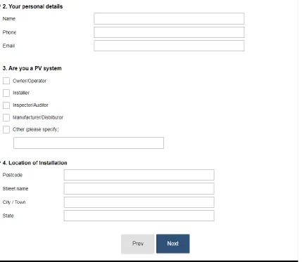
to further stages. Next, the user has the opportunity to provide personal details, installation details, and
system description. At this stage, the user may also specify if he or she is an end user or a
33
After that, the respondent has to go through all the five sections in the following order: Module, Inverter, Other Equipment, Installation and General Issues. In the Module section, the respondent may report any failures associated with the module. The user has to provide further details on each reported failure as shown in Figure 7 and summarised in Note 3 (Page 35). Then the user is offered a chance to go back and report any other failures related to the module. When all the PV modules failures are added, the respondent has the opportunity to report module certification and/or labelling issues encountered. If there is no module certification and/or labelling issues to report, then the user has to go through the other four sections. The user is also able to go back to add new failures or edit previous entries.
After completing all the required details of all five sections, the user could add further information such as photographs, and a means of communication (an email or phone number) if the respondent did not do that previously.
34
Figure 7: The Original Version of PVFRP Methodology
Notes:
Note 1: In the Module and Inverter sections, only one failure at a time can be reported. Note 2: For the Certification and/ or Labelling issues, Other Equipment, Installation, and General Issue sections, the user can report multiple failures at a time.
Note 3: The respondent provides further detail on:
the type of problem;
how many of the selected components had this problem;
if the system performance has reduced because of this problem and a quantification of the reduction (%);
35
if the issue has been resolved or not, by whom and how it was resolved, and how long the problem lasted before it was fixed.
3.1.3
The Revised Version of The PV Module and System Fault
Reporting Portal
The structure of the revised version and how the data is collected is explained below and screenshots of the questions of the revised version of PVFRP and shown and described in
Error! Reference source not found..
Initially, the user has to go to the introduction section and declare that he or she read and understood the safety instructions as shown in Figure 25 and Figure 26 in Error! Reference source not found..
After that, the user has to provide personal details, installation details, and system description.The user is encouraged to provide a means of communication; however, it not compulsory to provide a means of communication. Providing postcode is made compulsory in the revised version as can be seen in Figure 27 and Figure 28 (Error! Reference source not found.).
In this stage, the user may specify if he or she is an end user of PV system or a specialist of PV system.
Next, the respondent is asked to choose any one of five different sections: Module, Inverter, Other Equipment, Installation and General Issues section ( Figure 29 in Error! Reference source not found.).
36
Error! Reference source not found. and can be seen in Figure 29 and Figure 36 and Figure 42 and Figure 45
If the user chooses the PV Module section, he or she will be first able to report any failures associated with the module and provide further details of each reported failure. Then the respondent is offered an opportunity to choose any module certification and/or labelling issues encountered.
Then the user is also able to go back to add new failures or edit previous entries.
After completing all the required details of all reported failures, the user could add further information such as photographs, and a means of communication (an email or phone number) if the respondent did not supply that previously.
Finally, the user will be able to submit the survey.
With, the revised version of PVFRP is more efficient because providing postcode is made compulsory, and the user is more encouraged to offer a means of communication in order to clarify any of the details the user has provided. Therefore, the data could be analysed for different climate zones or locations if a sufficient number of responses are received. The user could consume less time using the revised version of this survey due to the following two changes:
Providing information such as country and street number (installation details), and organisation (personal information) was removed from the revised version of this survey,
The user has a chance to select the section that fits the failure that needs to be reported, and he or she can skip unnecessary parts.
37
3.2
Thesis Methodology
In this section, the methods used to complete the project objectives are outlined. An overview of the methodology used for this thesis project is shown in the block diagram in Figure 8. This thesis project is aimed to evaluate the information about the failure associated with the PV systems specifically in Australia, potential causes which accelerate those failures to occur or develop further. In order to address this, the following procedures were obtained:
Background research about the PVFRP and failures in PV systems was obtained. Data from both versions of PVFRP was downloaded and filtered
1. International entries removed.
2. Entries with no useful details were removed.
3. Entries with insufficient or misguided descriptions were removed.
The literature review findings in this field of study were summarised.
The methodologies used and findings of (Köntges et al. 2017), (Köntges et al. 2014), and (Zaman, Parlevliet, and Calais 2015) contribute to the design of this thesis.
Then the data in each of the five sections (: Module, Inverter, Other Equipment, Installation, and General Issues) was analysed and compared with the findings from the literature.
38
39
4.
Chapter 4 - The Result and Evaluation of the Original Version of
PVFRP
4.1
Introduction
In the following subsections, the data after 41 months of operation of the original version of the PVFRP is evaluated, presented and compared with the findings from the literature review.
4.2
General Findings
The composition of the original version of PVFRP is presented in Figures 9 to 13 in order to check the representativeness of the data with respect to the most essential PV system characteristics.
During the operation of the original version of the survey (41 months), a total of 124 respondents have reported issues associated with PV system components and installation in Australia. Figure 9 demonstrates the type of respondents reported using this online questionnaire. The majority of failures have been reported by the owner/operator (57 users) and 20 installers. For this reason, the data had been filtered, validated. Inconclusive entries were verified through follow up where a means of communication had been obtained.
Figure 9: Respondents by Types Owner/Operator,
57
Installer, 20
Inspector/Auditor, 5
Manufacturer/Distributor, 2
Industry Association, 2
Solar Farm Operator and builder, 1 Repairer/business owner, 1
designer, 1
student, 1
consumer advocate, 1
40
Figure 10 shows the geographical distribution of the respondents. While one report had been recorded from Australian Capital Territory, Three from South Australia, most of the other States recorded between eight to thirteen reports. However, there had not been any reports from the Northern Territory and Tasmania.
Figure 10: PV Systems by Locations
More than the half the respondents (76 out of 124) did not provide the postcode (entry was not compulsory in the original version of the PVFRP).
41
Figure 11: PV Systems by Size
Figure 12: PV Systems by Type
Figure 13 indicates the number of entries for each of the different sections.
0 to 1 kW, 3
1.1 to 3 kW, 20
3.1 to 5 kW, 22 5.1 to 10 kW, 7
Larger than 10 kW, 9
Unanswered, 63
Grid connected with batteries, 3 Standalone/Off-grid,
6 Grid connected
without batteries, 70
42
Figure 13: Distribution of Different Fault Reports
4.3
PV Module Section
4.3.1
Module Failure Types
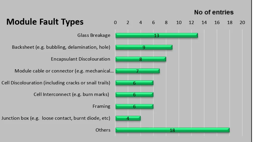
The repoted failure types vary broadly, and are fairly evenly distributed over the different types (84 entries). Glass breakage (13 entries), and backsheet issues (9 entries) were found to be slightly more common as can be seen in Figure 14 and Error! Reference source not found.. Glass breakage issue discussed in section 2.3.1.2.
Entry for Module,
85 Entry for Inverter, 90
Entry for other equipment, 74
Entry for Installations,
134
Entry module certification, 19
43
Figure 14:Module Failure Types
The other failures found within the PV module reported failures included: Water ingress encapsulant discolouration issues, and loose connection in the junction box which can create a spark that could cause subsequent arcing and/or fire. The problems reported in the module section are similar to those failures found during a visual inspection (Kontges et al., 2014) and the IEA survey (Köntges et al. 2017). For example, delamination, bubbling, burnt diodes, and loose contacts within junction box are found in all these three studies. In general, the PV module failures reported up to October 2017through the PVFRP are similar to those found in other papers which analysed the development of operational failure in PV
4.3.2
Module Certification and/or Labelling Issues
There are 19 entries with the certification and/or labelling of PV modules which can be seen in Table 1. The system with non-certified components used in modules, and modules that are not correctly labelled are found to be the top three issues
13 9 8 7 6 6 6 4 18
0 2 4 6 8 10 12 14 16 18 20
Glass Breakage
Backsheet (e.g. bubbling, delamination, hole)
Encapsulant Discolouration
Module cable or connector (e.g. mechanical…
Cell Discolouration (including cracks or snail trails)
Cell Interconnect (e.g. burn marks)
Framing
Junction box (e.g. loose contact, burnt diode, etc)
Others
44
Table 1: Certification Issues of PV Modules
Failure Types
No of Failures Reported Poor quality modules are being sold as
top quality products 1
Non-certified components used in
modules 4
Modules are not CEC approved 2
Modules are not correctly labelled 4 Modules have lower power ratings
than the nameplate ratings 1
Modules do not have manufacturer's
warranty 3
Have but not identify
4 Total
19
4.4
Inverters
45
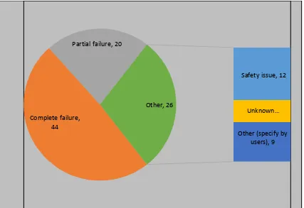
Figure 15 Inverter Failure Types
Table 2: Inverter Failure Types
Failure Types
No of Entries
Safety issue 12
Complete failure 44
Partial failure 20
Unknown 5
Others 19
Total 90
The other failures found within the PV inverter reported failures included: Safety issues, and unknown failure and other inverter issues. Respondents also commented on inverter safety and performance failures. Three of the inverter reported failures only affected system performance and did not make major failure in the PV system. These three failures are:
Overheating because of leaf develop in the heat-sink,
Safety issue, 12
Complete failure, 44
Partial failure, 20
Unknown…
46
The inverter is turning off because of grid frequency variation outside its operating range,
Faults with inverter control programming,
There are fewer studies that concentrate on the failures in relation to inverters compared to those studies obtained associated with failures in modules. The findings within the inverter section confirm the general trend in the literature that inverter is important category of PV system failures (Kurtz, Granata, and Quintana 2009). Therefore, there is an urgent need to identify and eliminate unreliable inverters.
4.5
Other Equipment
Other than failures in modules and inverters, failures in other PV systemcomponents can lead to safety fault or a reduction in PV system performance. There are 74 entries in Other Equipment section (Table 3) which include: 16 failures with the PV array isolator, 14 failures with rooftop isolators, 13 failures with the mounting structure, 9 failures with the main DC cable, 7 failures with the battery and 6 failures with the optimiser.
Failures in the battery are also recognised in the “All India Survey of Photovoltaic Module Degradation” in 2014 (Chattopadhyay et al. 2015).
Table 3: Other Equipment Issues
Other Equipment Issues Total
Framing/mounting structure 13
Rooftop isolator 14
PV array isolator 16
Battery 7
Optimiser 6
Main DC cable 9
Other 9
47
4.6
Installation Issues
Even though installation has be done based on Australian standards, there are reported failures associated with improper installation.
Table 4: Installation Issues Types
Installation issues Total
Inadequate cable protection 17
Water ingress into component enclosures 11
Inappropriate array location 10
Use of standard multicore TPS cable for DC 10
Incorrect rating of components (please specify which component, i.e. cable, isolator,
fuse etc) 10
Insufficient array fixing 9
PV system not allowing roof self-cleaning i.e. build-up of leaves etc. 8
DC and AC wiring inadequately segregated 8
Inadequate sealing of roof penetrations (i.e. roof leaking) 7
Inappropriate location for inverter (i.e. poor access, poor ventilation, exposed to direct
sunlight, etc) 6
Inadequate earthing of module frames 7
Missing or inadequate documentation 6
Incorrect wiring of polarised DC circuit breaker 5
Exposed live conductor 4
Insufficient ventilation limiting airflow around modules 4
Incorrect or inappropriate labelling 4
Incorrect functional earthing 3
Parallel strings with different number of modules connected in series to the same
MPPT or charge controller 3
Corrosion of equipment due to contact between dissimilar metals 2
Total 134
There are 134 entries to the original version of PVFRP associated with installation in PV systems and components which dominate all the reported failures to this particular survey. An inadequate cable protection and water ingress into component enclosures are two major problems identified (Even though installation has be done based on Australian standards, there are reported failures associated with improper installation.
48
Figure 16: Installation Issues Types
Some safety problems were also reported such as incorrect wiring of polarised DC circuit breakers, inadequate earthing of module frames, inadequate sealing of roof penetrations, water ingress into component enclosures, exposed live conductor, missing or inadequate documentation, incorrect wiring of polarised DC circuit breaker and incorrect rating of components (e.g. isolators, fuses, and cable).
49
documentation, inappropriate or incorrect labelling, an inadequate or incorrect rating of the component, and use of standard multi-core TPS cable for DC.
50
5.
Chapter 5 - The Result and Evaluation of the Revised Version of
PVFRP
5.1 Introduction
In the following subsections, the data after two months of operation of the revised version of the PVFRP is evaluated, presented and compared with the findings from the literature review.
5.2
General Findings
The composition of the revised version of PVFRP is presented in Figures 17 to 21 in order to check the representativeness of the data with respect to the most essential PV system characteristics.
51
Figure 17: Respondents by Types
52
Figure 18: PV Systems by Locations
The sizes of systems reported vary broadly, with most of the reports lodged for systems of 1.1kW to 5kW (28 systems) as can be seen in Figure 19. Most of the PV systems reported are grid-connected PV systems without batteries (21out of 38). There are also 7 PV systems are grid connected with batteries Figure 20.
10
5
4
3
2 2
1
11
0 2 4 6 8 10 12
WA QLD VIC NSW SA ACT Tasmania Unanswered
53
Figure 19: Systems by Size
Figure 20: System by Types
Figure 21 illustrates the number of entries for each of the different sections.
Grid connected with batteries, 7
Standalone/Off-grid, 0
Grid connected without batteries,
21
54
Figure 21: Distribution of Different Fault Reports
5.3
PV Module Section
5.3.1
Module Failure Types
The repoted failure types vary broadly (26 entries). Glass breakage (5entries) was found to be slightly more common as can be seen in Figure 22 and
55
Figure 22: Module Failure Types
The other failures found within the PV module reported failures included: Framing issues, encapsulant discolouration issues, and cell interconnect. The problems reported in the Module section are similar to those failures found during a visual inspection (Kontges et al., 2014) and the IEA survey (Köntges et al. 2017). For example, delamination, bubbling, burnt diodes, and loose contacts within junction box are found in all these four studies. Cell discolouration issues including cracks or snail trails were not reported in the revised version. In general, the PV module failures reported through the revised version of PVFRP are similar to those found in the original version of the PVFRP.
5.3.2
Module Certification and/or Labelling Issues
There are 11 entries with the certification and/or labelling of PV modules which can be seen in 5 4 4 4 3 2 2 2
0 1 2 3 4 5 6
Glass Breakage
Framing
Encapsulant Discolouration
Cell Interconnect (e.g. burn marks)
Junction box (e.g. loose contact, burnt diode, etc)
Backsheet (e.g. bubbling, delamination, hole)
Module cable or connector (e.g. mechanical damage, overheating)
Others
56
Table 5. The modules that are not CEC approved, and modules that do not have manufacturer's warranty are found to be the top three issues.
Table 5: Certification Issues of PV Modules
Failure Types
No of Failures Reported
Non-certified components used in modules 1
Modules are not CEC approved 3
Modules are not correctly labelled 1
Modules do not have manufacturer's warranty 2
have but not identify 4
total 11
5.4
Inverters
There are 24 entries associated with failures in inverters (
57
Figure 23 Inverter Failure Types
Table 6: Inverter Failure Types
Failure Types
No of Entries
Complete failure 9
Partial failure 6
Other (specify by users) 6
Safety issue 2
Unknown 1
Total 24
5.5
Other Equipment
There are 23 entries in Other Equipment section (Error! Reference source not found.) w hich include: 5 failures with rooftop isolators, 4 failures with the framing/mounting structure, 4 failures with the main DC cable, 3 failures with the PV array isolator, 3 failures in the battery, and 2 failures with the optimiser. Failures in the the battery are also recognised in the “All India Survey of Photovoltaic Module Degradation” in 2014 (Chattopadhyay et al. 2015) and revised version of PVFRP. In general, the findings within
Complete failure, 9
Partial failure, 6
Other (specify by users), 6
Safety …