10
CONTEMPORARY
ORDINARY LEVEL PHYSICS
LABOLATORY PRACTICAL GUIDE
INTRODUCTION
This book has tried to cuter many areas in ordinary level physics where the practical demonstration is of most important. The experiments in this book comprises the topics of mechanics, light, and electricity, The book also highlighted all the possible sources of errors in every experiment. Most of the topics and experiments explained in this book are in accordance of ordinary level physics secondary school syllabus
TABLE OF CONTENTS
CHAPTER ONE
MECHANICS page Acceleration due to gravity with simple pendulum……… 5-18 Acceleration due to gravity with spiral spring…... 18-35 Principle of moments………. 36-43 Density of materials……….. 41-44 Oscillating bodies……….. 45
CHAPTER TWO
LIGHT
Glass block……….. 47-53 Triangular glass prism……….. 53-58 Refractive index of liquids………... 59-60 Plane mirrors………... 61-68 Radius of curvature……… 70-71
CHAPTER ONE
CHAPTER ONE
BASIC EXPERIMENTS IN MECHANICS
EXPERIMENTS INVOLVING DETERMINATION OF ACCELERATION DUE TO
GRAVITY
SIMPLE PENDULUM EXPERIMENTS EXPERIMENT NO 1
The aim of this experiment is to determine the acceleration due to gravity using a simple
pendulum. You’re provided with a thread, pendulum bob, metre rule, cork, retort stand and a stop watch or stop clock. Hang the pendulum bob on one end of 100-cm length of thread and clamp the other end firmly on the retort clamp using cork. The clamp should be fixed at the edge of the laboratory bench as shown in side and front view diagrams below.
Retort stand inextensible string L Bob
A D
Pull the pendulum bob aside at a small angle so that it swings with small amplitude. Find the time t for 50
oscillations as it swing from point A via C to D. Repeat this procedure with the lengths of thread of 80cm,
60cm, 40cm and 20cm.
Tabulate your results including the column of period T (second) and T2
Length L (m) Time t for 50 osc(s) Period T(s) T2(s2)
1.0 0.8 0.6 0.4 0.2
(a) Plot the graph of lengths L(m) of the thread against T2 (b) Find the slope of the graph
(c) Using the relationship T= 2
g L
Find the value of acceleration due to gravity g
(d) State all possible sources of errors in this experiment and state the precautionary measures that are to be taken in order to reduce the effect of those errors
SOURCEES OF ERRORS IN THE EXPERIMENT Environmental sources
Wind resistance to the oscillating motion of a pendulum bob
Measurement sources
Errors in measurement of length which may include parallax and zero error of the measuring devices Error in timing device like stop watches (errors in starting and stopping a stop watch)
Large angle of displacement of the bob which may disturb to and fro movement of the bob
Graphing error
Uses of blunt pencil in drawing graph Too much estimation when drawing graph
PRECAUTIONARY MEASURES IN REDUCING THE EFFECTS OF ERRORS
-Conduct the experiment in a part of the laboratory free from drought -Zero error of the metre rule should do be treated
-Angle of displacement of the bob should be kept as small as possible -Sharp pencil should be used in drawing graph
-Choose far point when calculating gradient
-Repetition in taking data and uses of average data should be done -Avoid unnecessary estimation of data or truncation
EXPERIMENT NO 2
The aim of this experiment is to determine the acceleration due to gravity using a simple pendulum. You’re provided with a thread, pendulum bob, metre rule, cork, retort stand and a stop watch or stop clock. Hang the pendulum bob on one end of 100-cm length of thread and clamp the other end firmly on the retort clamp using cork. The clamp should be fixed at the edge of the laboratory bench as shown in side and front view diagrams below.
clamp
Retort stand inextensible string
L Bob
Pull the pendulum bob aside at a small angle so that it swings with small amplitude. Find the time t for 50 oscillations as it swing from point A via C to D
Repeat this procedure with the lengths of thread of 80cm, 60cm, 40cm and 20cm Tabulate your results including the column of period T (second) and T2
Length L (m) Time t for 50 osc(s) Period T(s) T2(s2)
1.0 0.8 0.6 0.4 0.2
(a) Plot a graph of T2 against lengths of the thread L(m) (b) Find the slope of the graph
(c) Using the relationship T= 2
g L
Find the value of acceleration due to gravity g
EXPERIMENT NO 3
The aim of this experiment is to find the acceleration due to gravity g and the ratio Q defined in part (d) by using a simple pendulum
Suspend the pendulum bob with its upper part of the string fixed on a retort clamp as shown in fig.1 below. Make a knot Nat a distance of L =10cm from the bob B. While X is the distance between the point of suspension S to a knot N on the string
Set X=60cm and pull the bob aside at a small angle so that it can start swinging vertically
X
N
L=10cm
(b) Repeat the above procedure for the values of X= 50, 40, 30, 20 and 10cm and record all the time t for each respective oscillations and calculate the period T. tabulate your results as shown below
A TABLE OF RESULTS
Length X (m) Time t for 20 osc(s) Period T (s) T2(s2)
0.6 0.5 0.4 0.3 0.2 0.1
(c) (í) plot a graph ofT2 against X (íí) find a slope S of the graph
(ííí) from the graph read and record the value of T2 when X =0
(e) Evaluate Q where Q=
S T2
(f) Find the acceleration due to gravity g given that g =
S
2
4
(g) State all possible sources of errors in this experiment and state the precautionary measures that are to be taken in order to reduce the effect of those errors
SOURCEES OF ERRORS Environmental sources
Wind resistance to the oscillating motion of a pendulum bob
Measurement sources
Errors in measurement of length which may include parallax and zero error of the measuring devices
Error in timing device like stop watches (errors in starting and stopping a stop watch) Large angle of displacement of the bob which may disturb to and fro movement of the bob
Graphing error
Too much estimation when drawing graph
Taking very close points when calculating slopes from graph
PRECAUTIONARY MEASURES IN REDUCING THE EFFECTS OF ERRORS
-Conduct the experiment in a part of the laboratory free from drought -Zero error of the metre rule should do be treated
-Angle of displacement of the bob should be kept as small as possible -Sharp pencil should be used in drawing graph
-Choose far point when calculating gradient
EXPERIMENT NO 4
You’re required to determine the height of the laboratory bench and the acceleration due to gravity g.
Proceed as follows;
(a) Tie one end of the pendulum bob to the pendulum bob and fix the other end of the thread to the edge of the bench with a small nail keeping the height from floor to the pendulum bob as h = 5cm As shown in fig 1 below
Laboratory bench
Inextensible string
Bob h
Floor
(b)Displace the pendulum through a small angle to one end and set it to oscillate with small amplitude. Record the time for 30 oscillations hence determine the period T for one complete oscillation
Increase the height h above the floor by 5cm interval such that you obtain four other values of h and repeat the procedure in (b) above
(c) (i) Tabulate your results
(ii) Plot the graph of T2 (y- axis) against h (x- axis)
(iii) Determine the slope of the graph and find the acceleration due to gravity g using the relation
g H g
h T
2 2
2 4 4
(d) State all possible sources of errors in this experiment and state the precautionary measures that are to be taken in order to reduce the effect of those errors
SOURCEES OF ERRORS Environmental sources
Wind resistance to the oscillating motion of a pendulum bob
Measurement sources
Errors in measurement of length which may include parallax and zero error of the measuring devices
Error in timing device like stop watches (errors in starting and stopping a stop watch)
Large angle of displacement of the bob which may disturb to and fro movement of the bob
Graphing error
Uses of blunt pencil in drawing graph
Too much estimation when drawing graph
Taking very close points when calculating slopes from graph
PRECAUTIONARY MEASURES IN REDUCING THE EFFECTS OF ERRORS
-Conduct the experiment in a part of the laboratory free from drought
-Zero error of the metre rule should do be treated
-Angle of displacement of the bob should be kept as small as possible -Sharp pencil should be used in drawing graph
-Choose far point when calculating gradient
EXPERIMENT NO 5
The aim of this experiment is to determine the acceleration due to gravity gat your school and the constant TC for a ruler provided
Set up the apparatus as shown in the fig below; Clamp (vice)
Lr
Bench metre rule
Inextensible string Bob L
(a) By using a bench clamp fix a metre ruler on one leg of a bench as shown in the fig above. The flat part of the metre ruler projection should rest horizontally so that the length Lr = 80cm. by means of a thin inextensible string suspend the pendulum bob so that the length of the string L = 80cm. displace the bob through a small angle and set it to oscillate along the direction of the ruler with small amplitude. Record the time t for 30 oscillations made hence find the period T for one oscillation and find the value T2
(b) Without altering the value of Lr ( keep it 80cm) repeat the procedure in (a) above for the values of string length L = 70, 60, 50, 40, 30 and 20cm
(c) Tabulate your results in a table below
Length of string L
(m)
Time t for 20 osc (s)
Period T(s) T2(s2) 0.8
(d) (i) Plot the graph of T2 against length of pendulum L
(ii) From your graph determine the acceleration due to gravity g at your school and also find the value
of the constant Tc given that Tc
g L T2 3949
(e) State all possible sources of errors in this experiment and state the precautionary measures that are to be taken in order to reduce the effect of those errors
SOURCEES OF ERRORS Environmental sources
Wind resistance to the oscillating motion of a pendulum bob
Measurement sources
Errors in measurement of length which may include parallax and zero error of the measuring devices
Error in timing device like stop watches (errors in starting and stopping a stop watch) Large angle of displacement of the bob which may disturb to and fro movement of the bob
Graphing error
Uses of blunt pencil in drawing graph Too much estimation when drawing graph
Taking very close points when calculating slopes from graph
PRECAUTIONARY MEASURES IN REDUCING THE EFFECTS OF ERRORS
-Conduct the experiment in a part of the laboratory free from drought -Zero error of the metre rule should do be treated
-Angle of displacement of the bob should be kept as small as possible -Sharp pencil should be used in drawing graph
-Choose far point when calculating gradient
EXPERIMENT NO 6
The aim of this experiment is to find the ratio P defined in part (d) by using a simple pendulum Suspend the pendulum bob with its upper part of the string fixed on a retort clamp as shown in fig.1 below. Make a knot Nat a distance of L =10cm from the bob B. While X is the distance between the point of suspension S to a knot N on the string
Set X=60cm and pull the bob aside at a small angle so that it can start swinging vertically
X
N
L=10cm
(a) Record the time t for 30 oscillations of the pendulum bob
(b) Repeat the above procedure for the values of X= 50, 40, 30, 20 and 10cm and record all the time t for each respective oscillations and calculate the period T. tabulate results for X, t, T and T2
(d) Determine the value of the slope and Y-intercept of the graph
(c) Compute the ratio
S ercept Y
P int
(d) State all possible sources of errors in this experiment and state the precautionary measures that are to be taken in order to reduce the effect of those errors
SOURCEES OF ERRORS Environmental sources
Wind resistance to the oscillating motion of a pendulum bob
Measurement sources
Errors in measurement of length which may include parallax and zero error of the measuring devices
Error in timing device like stop watches (errors in starting and stopping a stop watch) Large angle of displacement of the bob which may disturb to and fro movement of the bob
Graphing error
Uses of blunt pencil in drawing graph Too much estimation when drawing graph
Taking very close points when calculating slopes from graph
PRECAUTIONARY MEASURES IN REDUCING THE EFFECTS OF ERRORS
-Conduct the experiment in a part of the laboratory free from drought -Zero error of the metre rule should do be treated
-Angle of displacement of the bob should be kept as small as possible -Sharp pencil should be used in drawing graph
-Choose far point when calculating gradient
DETERMINATION OF ACCELERATION DUE TO GRAVITY A SPIRAL SPRING
BY USING
EXPERIMENT NO 7
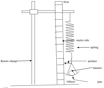
The aim of this experiment is to determine the acceleration due to gravity g Proceed as follows
0cm
Spiral spring
A metre rule Pointer
100cm
(a) Set up the apparatus as shown in the fig note that the metre rule has its zero mark at the top. Record the pointer reading Xo. Put on the scale a mass of 50g and record the new pointer reading X on the metre rule. Calculate the extension S = X – Xo corresponding to the added mass repeat the procedure for a series of masses in steps of 50g until you obtain five more reading. Tabulate your results for m, X and S
(b) With mass m1 of 200g on the scale pan pull the spring through a small distance and release it. Record the time for 10 oscillations and determine the period T1. Repeat this procedure for another mass m2 of 300g and find its periodic time T2
(d) Calculate the acceleration due to gravity g given that 2 1 2 2
1 2 2
4
T T
m m G g
(e) State any sources of errors and precautions to be taken
EXPERUMENT NO 8
The aim of this experiment is to determine the acceleration due to gravity g and the constant H. Set up the apparatus as shown in the fig below whereby a spiral spring is tied to the clamp of a retort stand with an inextensible cotton string. A wooden block of mass 150g is hanged on the lower part of the spring. Measure the height h from the floor to the point of attachment of the block
Retort stand
Cotton thread
Spiral spring
Bench wooden block
h floor
(a) Pull the block downward and release it so that it can swing with vertical oscillations. This is a simple harmonic motion. Measure the time t for 20 complete oscillations and hence determine the corresponding period T for the motion then calculate the value of T2
(c) Tabulate the values of m, t, T and T2
(d) (i) Plot a graph of h against T2
(ii) Determine the slope of your graph
(iii) If h and T are related through the equation
2 2
4
gT H
h Find the value of g and H
(e)State all possible sources of errors in this experiment and state the precautionary measures that are to be taken in order to reduce the effect of those errors
SOURCEES OF ERRORS Environmental sources
Wind resistance to the to the motion of the spiral spring
Measurement sources
Errors due to due to poor setting of the experiment(setting of pointer) Errors due to the uses of exhausted spring
Errors in measurement of length which may include parallax and zero error of the measuring devices
Error in timing device like stop watches (errors in starting and stopping a stop watch)
Graphing error
Uses of blunt pencil in drawing graph Too much estimation when drawing graph
Taking very close points when calculating slopes from graph
PRECAUTIONARY MEASURES IN REDUCING THE EFFECTS OF ERRORS
-Conduct the experiment in a part of the laboratory free from drought -Zero error of the metre rule should do be treated
-Sharp pencil should be used in drawing graph -Choose far point when calculating gradient
-Repetition in taking data and uses of average data should be done -Avoid unnecessary estimation of data or truncation
EXPERIMENT NO 9
The aim of this experiment is to find the acceleration of the weights Proceed as follows;
Spiral spring
brick
Bench cellotaped pointer
metre rule
Clamp one end of the spring on a retort stand and attach the hunger to the lower end. Arrange the retort stand such that the spring is over the end the end of the bench and the bottom of the hunger is about 5cm below the edge of the bench. Make sure that the retort stand is firm by putting a brick on the base. Use cellotape to fix the pin onto the bottom of the hungers that it forms a horizontal pointer. Use the second retort stand to fit a metre rule vertically in such a way that the zero mark is on top and the pointer is horizontal across the scale
Note the position Po of the pointer on the scale. Add a 50g mass to the hunger and note the new pointer reading P. set the spring and added mass into vertical oscillations with small amplitudes. Find the periodic time T by timing a suitable number of vertical oscillations. Repeat the same procedure with added masses of 70g, 90g, 110g, and 150g.
Tabulate your results and plot a graph of extension X of the spring against the square of the periodic time (T2)
(b) What does G represent?
(c) Mention any two sources of errors and precautions taken
E
XPERIMENT ON EXTENSION AND
H
OOKE
’
S LAW
EXPERIMENT NO 1
The aim of this experiment is to verify the Hooke’s law and to find the value of the rubber band constant
Proceed as follows;
Set up the apparatus as shown in the fig below. A rectangular wooden graduated metre rule is clamped uprightly using a retort stand. A rubber band is tied to a second retort stand with a pointer and a hanger on the lower parts of the rubber band. The two clamps are to be placed near each other so that the pointer should lie horizontally and perpendicular to the graduated metre rule. Read the length as indicated by the pointer Lo
(a) Load a mass of 100g on the hanger and record the length as indicated by the pointer. Find the extension
(b) Keep on loading the hanger with 100g weight until the total mass became 500g and in each time calculate the extension caused by loading up to 200g, 300g, 400g and 500g.
(c) Unload the masses on the hanger by removing 100g consecutively from the hanger while calculating the extension in each time
0cm Metre ruler
Pointer Rubber band
A hanger and weight
(d)Tabulate the result as shown in a table below
Mass(g) Weight(N) Loading
extension(m)
Unloading extension(m)
Average extension (m)
(d) (i) Plot the graph of weight against average extension (ii) From the graph deduce its slope
(iii) What is the significant meaning of the slope deducted in in above
(iv) State the law which relate the weight and the corresponding extension as indicated by the graph drawn in
SOURCEES OF ERRORS Environmental sources
Wind resistance to the to the motion of the spiral spring
Measurement sources
Errors due to due to poor setting of the experiment(setting of pointer) Errors due to the uses of exhausted spring
Errors in measurement of length which may include parallax and zero error of the measuring devices
Error in timing device like stop watches (errors in starting and stopping a stop watch)
Graphing error
Uses of blunt pencil in drawing graph Too much estimation when drawing graph
Taking very close points when calculating slopes from graph
PRECAUTIONARY MEASURES IN REDUCING THE EFFECTS OF ERRORS
-Sharp pencil should be used in drawing graph -Choose far point when calculating gradient
-Repetition in taking data and uses of average data should be done -Avoid unnecessary estimation of data or truncation
-proper setting of the experiment - uses of spring which are strong
EXPERIMENT 2
The aim of this experiment is to determine the mass of given object B and the constant of the spring provided
(i) Set up the apparatus as shown in the fig below with a zero mark of a metre rule at the top of the rule and record the scale reading by the pointer So
Clamp 0cm
Metre rule
Pointer
Retort stand
Pan
100cm
(ii) place the object B and standard weight(mass) W equal to 20g in the pan and record the new pointer reading S1. Calculate the extension e = S1- So in cm
(a) Record your result in tabular form as shown below Table of results
Mass(kg) Force F(N) Pointer reading
S1(cm)
Extension e = S1-So (cm) 0
0.02 0.04 0.05 0.06 0.08 0.10
(b) Plot the graph of Force F (N) (vertical axis) against extension e (horizontal axis) (c) Use you graph to evaluate
(h) mass of B
EXPERIMENT NO 3
In this experiment you’re required to the unknown mass labeled Mo using a spiral spring. Your provided with the following apparatus;
A metre rule, retort stand with two clamps, a spring, pointer, scale pan, and masses. Arrange your apparatus as shown in the following diagram
0cm
metre rule spring
Retort clamp pointer masses
100cm pan Proceed as follows;
(a) Read and record the initial position of the pointer So while there is no any mass in the scale pan. Add onto the scale pan a mass of 50g and note the new position S of the pointer.
(b) Calculate the extension e = S – So.
(c) Repeat the same procedure for the rest of the masses and tabulate your results as shown in the table below.
So = ……….cm
Mass M (gm) S(cm) e = S – So (cm)
(d) (i) plot a graph of mass M(vertical axis) against extension e (horizontal axis) (ii) obtain the slope S of your graph
(iii) what does the slope represent?
SOURCEES OF ERRORS Environmental sources
Wind resistance to the to the motion of the spiral spring
Measurement sources
Errors due to due to poor setting of the experiment(setting of pointer) Errors due to the uses of exhausted spring
Errors in measurement of length which may include parallax and zero error of the measuring devices
Error in timing device like stop watches (errors in starting and stopping a stop watch)
Graphing error
Uses of blunt pencil in drawing graph Too much estimation when drawing graph
Taking very close points when calculating slopes from graph
PRECAUTIONARY MEASURES IN REDUCING THE EFFECTS OF ERRORS
-Conduct the experiment in a part of the laboratory free from drought -Zero error of the metre rule should do be treated
-Sharp pencil should be used in drawing graph -Choose far point when calculating gradient
-Repetition in taking data and uses of average data should be done -Avoid unnecessary estimation of data or truncation
EXPERIMENT NO 4
In this experiment your are required to determine the mass of unknown object X Clamp
metre rule
spiral Spring
Pointer
Pa
Assemble the pieces of apparatus as shown in the fig above, with zero mark scale of the rule at the lower most end.
Record the reading of the position of the pointer on scale of metre rule when the pan is empty as So Put 20g to the pan and record pointer reading S.
Find the extension e= S – So,cm,
Repeat the procedure for the mass of 40g, 60g, 80g, and 100g. Put object X on the pan and record its pointer reading
(a) Summarize your results in a table as follows;
Mass on the pan(g) 20 40 60 80 100 X
Pointer reading(cm) Extension, e = S – So(cm)
(b) Plot the graph of mass against extension (c) Find the slope P of your graph
(d) Find mass X
(f) Comment on Q and X SOURCEES OF ERRORS Environmental sources
Wind resistance to the to the motion of the spiral spring
Measurement sources
Errors due to due to poor setting of the experiment(setting of pointer) Errors due to the uses of exhausted spring
Errors in measurement of length which may include parallax and zero error of the measuring devices
Error in timing device like stop watches (errors in starting and stopping a stop watch)
Graphing error
Uses of blunt pencil in drawing graph Too much estimation when drawing graph
Taking very close points when calculating slopes from graph
PRECAUTIONARY MEASURES IN REDUCING THE EFFECTS OF ERRORS
-Conduct the experiment in a part of the laboratory free from drought -Zero error of the metre rule should do be treated
-Sharp pencil should be used in drawing graph -Choose far point when calculating gradient
-Repetition in taking data and uses of average data should be done -Avoid unnecessary estimation of data or truncation
EXPERIMENT NO 5
The aim of this experiment is to determine the spring constant, K of the helical spring provided (a) Set up the apparatus as shown in the fig above without the 200g mass, where
0cm
Helical spring Metre rule
A X B retort stand 0cm
2oog
100cm
(i) Points of suspension P and Q are 40cm apart,
Loops 1 and 2 are a at 5cm and 45cm marks respectively,
(ii) The pointer is attached to the lower end of the helical spring using plasticine, (iii) A short string connects the lower end of the spring to loop 2
(iv) Loop 1 is attached to P with a long string and
(v) The half metre rule AB is horizontal such that the edges A and B are at equal height from the bench. This is achieved by adjusting the length of the string suspended fro P
(b) Measure the height of the pointer from the bench. Record it as Yo
(c) (i) Suspend 200g mass provided, at loop 3. Use a short string.
(ii) Adjust loop 3 so that the 200g mass hangs at the 40cm mark i.e., X = 35cm
(iv) Record the distance, X between the loop 1 and 3 and measure the corresponding height, Y of the pointer from the bench. Hence determine Y – Yo.
(v) repeat the steps c) (ii),(iii) and (iv) for values of X = 30, 25, 20, 15, and 10cm. and record the corresponding values of Y and Y – Yo.
(d) Plot a graph of Y – Yo (y axis) against X
(e) (i) determine the slope S of the graph and hence (ii) Calculate the value of K given that
) (s PQ
M K
Where M = 200g and PQ = 40cm
EXPERIMENTS ON YOUNG`S MODULUS
EXPERIMENT NO 1
The aim of ths experiment is to determine the Young`s modulus of the material of the metre rule provided
Bench clamp L
So Metre rule S Weighing pan retort
Fig1
Clamp the metre rule firmly with a distance L of about 90cm. overhanging from the bench. The free end is such that it acts as a pointer along the metre rule clamped in the vertical position. Note the scale reading, So, on the vertical metre rule when the horizontal metre rule is not loaded.
B b
d
fig 2
Fasten the weighing pan at the free end of the horizontal metre rule with a piece of strong thread. Add on t o the weighing pan a mass of 20g and record the scale reading So on the vertical metre rule. Calculate the depression, D = S – So, corresponding to the added mass. Keeping the length L constant, add a series of masses from say 20g to 150g in steps of 10g or 20g with each added mass, record S and calculate D
(seefig1)
(a) Use vernier calipers to measure the breadth b and thickness d of the horizontal metre rule (See fig 2)
(b) Plot the graph of depression D against the added masses m (c) From your graph determine the slope
(d) Calculate the Young`s modulus Y of the material of the rule using the formula
slope bd
gL Y 3
3
4
EXPERIMENT NO 2
The aim of this experiment is to determine the Young`s modulus of a given metre rule Proceed as follows;
Use a vernier calipers to measure the breadth and thickness of the metre rule provided
Table G clamp
100cm
50g
h ho
take a metre rule and fix itat its 10cm mark by means of a G clamp. Record the height ho above the ground. Take a 50g weight (L) provided and suspend it on the metre rule at 90cm mark using a string. Note the new height h above the ground. Repeat the above procedure by suspending the weights of 100g,
150g, 200g, 250g and 300g from the same position, each recording the new height h (a) Record your reading in a suitable table and include the column for (ho - h)
(b) Plot a graph of L(load) vertical axis against (ho - h) horizontal axis (c) From your graph find the slope G.
(d) Determine the Young`s modulus Y of the wooden metre rule given that
3
4
t Gb
Where
is the distance of point of the weight from the clamp, b is the breadth of he metre rule and t is the thickness of the wooden metre ruleEXPERIMENT NO 3
The aim of this experiment is to determine the Young`s modulus of a given metre rule Proceed as follows
Table G clamp
100cm 50g
d do
(a) Take a metre-rule (L) whose weight is provided and fix it at its 10cm mark by means of a G- clamp. Record the height (do) above the ground of the 50cm mark of the rule. Take the 50g
weight provided and suspend it on the metre rule at 50cm mark using a string. Note the length
of the rule between the position of the clamp and the position 50g- weight. Note also the new height (d )of the 50cm mark above the ground.(see the fig above)(b) change the position of the 50g-weight to 60cm,70cm, 80cm, 90cm and 100cm respectively and repeat the measurements as in (a) above each new position.
(c) Recrd your readings in a suitable table and include columns for X = do – d and 3
(d) Plot a graph of 3 (vertical axis) against X = do – d(horizontal axis) (e) Determine the slope of the graph
(f) Calculate the Young`s modulus (E) using the relation :
IE W X
3
3
12 .d3 b I
: b = width of the rule
D = thickness of the rule (Should be measured using the venire calipers provided)
EXPERIMENTS ON THE PRINCIPLE OF MOMENTS
EXPERIMENT NO 1
The aim of this experiment is to determine the mass of a given dry cell, size “AA” Your provided with a dry cell, a knife edge, two weights 50g and 20g and a metre rule Proceed as follows;
(a) Locate and note the centre of gravity C of the metre rule by balancing on the knife edge
(b) Suspend the 50g mass on one side of the metre rule and 20g together with a dry cell on the other side of the metre rule adjusting their position until the metre rule balances horizontally as shown in the fi below
C
a b
50g X g 20g
(c) By fixing a = 5cm from Find its corresponding length, b from C
(d) Repeat and tabulate your results using a = 10cm, 15cm, 20cm and 25cm. (e) Draw a graph of “a” against “b” and calculate the slope G
(f) Calculate X from equation
50 20 X G
EXPERIMENT 2
The aim of this experiment is to verify the principle of moments for parallel forces Proceed as follows;
(a) Find the centre of mass of a metre rule by placing it on the knife edge. Find the balancing point and put a mark on the point using a piece of chalk (or pencil).
a b
knife edge
W1 W2 Wooden block
(b) Suspend 100gf = W2 on the 10cm length on the right from the centre of the mass G of the metre rule. Suspend the 50gf = W1 on the left hand side of G and adjust the position of W1 until the metre rule balances in a horizontal position. Read and record the length “a” and “b” in the fig above
(c) Repeat the process in (b) above with W2 on the length 12.5cm,15.0cm,17.5cm, 20.0cm, 22.5cm
and 25cm. each time record the corresponding lengths “a” in the table below.
W1(gf) W2(gf) a(cm) b(cm) W1.a(gf-cm) W2.b(gf-cm)
50 100 10.0
12.5 15.0 17.5 20.0 22.5 25.0
(d) (i) complete the table above
(iii) State the principle of moment for parallel forces (iv) Comment on the relationship in (ii) and (iii) above
EXPERIMENT NO 3
The aim of this experiment is to determine the density of wood. Your provided with wooden bar, a knife and a 100g weight
Proceed as follows;
(a) Locate the centre of gravity C of the wooden bar by balancing freely about the knife edge (b) Suspend the 100g mass on the wooden bar as shown in the fig below; 10cm from C adjust the
position of the knife edge to get a balance.
A C B
1 100g
(c) Record the distance of the centre of gravity C from the knife edge as Y and distance between the knife edge and 100g mass as X.
(d) Repeat procedures (b) and (c) above by increasing the distance of the 100g mass to 20cm, 30cm, 40cm, 50cm and 60cm respectively from the centre of gravity C. tabulate your results.
Calculate the mass (M) of the wooden bar given that gradient
M G 100
(f) Measure the length
, width w and thickness t of the wooden bar and hence calculate the density of wood given thatDensity of wood,
wt M
EXPERIMENT NO 4
The aim of this experiment is to determine the relative density of a solid provide. Proceed as follows;
Y X = 100 – Y
0cm 100cm d
Knife edge metre rule
Mo solid
(a) Set up the apparatus as shown in the fig above. Balance the metre rule, graduated face upwards, on the knife edge when the solid is suspended in air at a distance dcm from the zero end of the rule measure the distance Ycm of the knife edge from the 0 end or Xcm from the 100cm end of the rule
Repeat for FOUR other values of d less than 50cm
(b) Repeat these observations with the same solid immersed in water
(c) Plot graphs with X-Y as ordinate and Y-d as abscissa. The two graphs of both sets of
observations should be drawn in th same sheet (page) of the graph paper and to the same scale (d) Find the gradient of each graph
HINT; do not forget to measure the mass of the wooden metre rule (Mr) by using a beam balance
EXPERIMENT NO 5
The aim of this experiment is to determine the weight of a body and its relative density by the principle of moment;
Proceed as follows;
Set up the apparatus as shown in the fig below
Clamp metre rule L2
L1 iron nail mg
Retort stand X g
bench
Suspend a metre rule clamped at 50cm mark.
Balance the metre rule by adjusting U- shaped upper wire so that the rule balances horizontally. Hang the unknown mass and volume of water in a weighed container at a 20cm mark. Hang the mass of 100g from other end of a metre rule and adjust the distance of this mass so that the rule balances again.
By the principle of moments determine the mass of water and its containing vessel. Repeat this procedures using methylated spirit of the same volume, in a weighed container.
(a) Measure the length of L1 and L2 when a vessel contains water L1 = ……. and L2 = …….
(c) Using the principle of moments find the mass of water and that of methylated spirit. (d) Calculate the relative density of methylated spirit
EXPERIMENT ON DENSITIES
EXPERIMENT NO 1
scale …
Liquid container ……….
….,.. ho
liquid
lead shot
test tube
Your provided with a test-tube with millimeter scale extending over its entire length. Put sufficient lead shots into the test tube to ensure that it just floats vertically in liquid, L, contained in a tall beaker. Keeping the floating test-tube away from the side of the beaker, read and record the height ho of the test- tube that is submerged as shown in fig above
Drop 4 clips into the test-tube and record the new height, h of the test-test that is submerged. Record five more heights by having 8, 12, 16, 20 and 24 clips respectively dropped into the test-tube. For each new height, h , calculate (h-ho). Tabulate N, h and (h-ho) where N is the number of clips dropped into the test-tube.
(a) Plot a graph of N against (h-ho). (b) Determine the slope G of your graph
(c) Measure and record the external diameter D of the test-test. (d) Find the value of 4 2
D G
, where is the average mass in grammes of a clip.
EXPERIMENT NO 2
(a) Given the following apparatus a vernier calipers , micrometer screw gauge, a weighing balance (beam balance) and 20 coins (two hundred shilling each)
(b) Measure the diameter d of one two hundred shilling by using a vernier calipers(in centimetre) (c) Measure the thickness t of one hundred shilling by using a micro meter screw gauge (in centimetre)
d
t
(d) Measure the mass of 2 coins provided by placing them on a beam balance and record the reading in gram
(e) Keep on adding coins onto the balance to 5, 8, 11, 14, 17, and finally 20 coins in each time record the mass of each respective numbers of coins on the balance
(f) Tabulate your results as shown below;
Numbers of coins n Mass coins (in grams)
2 5 8 11 14 17 20
(g) (i)Plot a graph of masses of coins (vertical axis) against numbers of coins (horizontal axis) (ii) Determine the slope S of the graph
(iii) Find the density of D of the material of the coin (in gram per centimetre) given that
2 . . 4 d t S D
(a) If one coin is immersed in an eureka can full of water , what mass of water will overflow (Assume water has a density of 1g/cm3 and π = 3.14)
EXPERIMENT NO 3
Proceed as follows
Fix the eureka can (or overflow can) on a block of wood and place one beaker under the spout of the can . pour water into the can until it overflows through the spout to the beaker until the last drop.
Take measure a 100g mass W1 and hang it on the lower end of the spring balance by using a thin inextensible cotton thread. Place an empty measuring cylinder on the spout of the can. Lower the 100g onto water until it is totally immersed in a can as shown in the fig below
Spring balance
Spout
Eureka can 100g mass
Water
Allow the overflowing water to run out via the spout to the measuring cylinder until the last drop. Read and record the new reading on the spring balance W2 and also record the volume of water collected in a measuring cylinder V
Repeat this procedure for the masses of 200g, 300g, 400g and 100g and tabulate your result as shown below
Mass W1(g) Mass W2 (g) Upthrust
N W W U
100
2 1
volume (cm3) Displaced weight of water = α x v 1000
Where α is the density of water and V is the volume of water displaced ( α = 1g/cm3 ) (a) Plot a graph of upthrust U versus displaced weight of water
(b) Find the slope of the graph
EXPERIMENT ON OSCILLATING BODIES
EXPERIMENT NO 1
The aim of this experiment is to investigate the relationship concerning the periodic time of bifilar pendulum
Proceed as follows;
50cm (appx) clamp
Retort stand
Half metre rule X
(b) Suspend the half metre rule by using threads of about 80cm each from the top of clamps which should be about 50cm apart as shown in fig above (which is not drawn to scale). The lower ends of the threads are looped to the rule at equal distances from the mid-point of the rule. Record the separation X between the loops Set the pendulum (the rule) swinging horizontally by displacing the ends of the rule in the opposite direction through a small angle. Determine the time t
different observations of t corresponding to X are obtained. Record your observations neatly. Also record the values of periodic time T (time for one oscillation) , log 10T and log 10X
(c) Assuming that
Tα X
n,
we haveT = k X
nwhere k is a constant and n is a fraction. Taking logarithms we obtainlog
10T = n log
10X + log
10k
with the origin at (0,0)
(d) Plot a graph of
log
10T
(vertical axis) against
log
10X
(horizontal axis) and hence determine
the values of n an k each correct to one decimal place
CHAPTER 2
L
IGHTEXPERIMENT S INVOLVING GLASS BLOCK
EXPERIMENT NO 1
The aim of this experiment is to determine the refractive index of the glass block provided. Proceed as follows;
Place a white sheet paper on the drawing board. On top of this white paper place the glass block with one of its largest faces top most. Mark its outline ABCD on the paper with a sharp pencil. Remove the block and draw a line that cuts AB normally at E and G (call it FEG)
F
H P1
P2
i
0A E B O
r0
D G I C
P3 P4
Draw a line HE making an angle of incidence
i
0 = 200 with EGF at O. Put the glass block in its original position and stick the first pin P1 and second pin P2 along the line HE of anglei
0 = 200 . The third and the fourth pins P3 and P4 respectively, should be stuck on the opposite side of the block such that they appear in a straight line with P1 and P2 when viewed through the side AB of the glass block. Remove the glass block and trace the straight path taken by the ray IP3P4. Join E and I using a ruleMeasure the angle of refraction r0 and the calculate the value of the values sin
i
0and sin
r0(a) Repeat the procedures above for an angle of incidence
i
0= 40
0, 50
0, 60
0and
80
0and in all cases
calculate the value of respective
sini
0and sin
r0A table of results
Angle of incidence
i
0 Angle of refraction r0 sini
0sin
r0200 400 500 600 800
(c) (i) Draw the graph of sin
i
0(y-axis) against sin
r0 (x-axis) (ii) Find the slope of the graph(iii) What is the physical meaning of the slope obtained in (c) (ii) above
(d) State all possible sources of errors in this experiment and state the precautionary measures that are to be taken in order to reduce the effect of those errors
EXPERIMENT NO 2
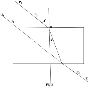
The aim of this experiment is to determine the refractive index of the glass block provided. Proceed as follows;
Place the given glass block in the middle of the drawing paper o n the drawing board. Draw lines along the upper and lower edge of the block and extend the line you have drawn. Represent the end of these lines segment as SS1 and TT1. Draw the normal NN1 to the parallel lines SS1 and TT1 as shown in the fig below
N
S O S1
N1 fig1
Draw five evenly spaced lines from O to represent the incident rays at different angles of incidence (100, 200, 300, 400 and 500from the normal). Replace the glass block carefully between SS1and TT1.
Stick two pins P1 and P2 as shown in the fig 2 as far apart as possible along one of the line drawn to represent an incident ray. Locate an emergent ray by looking through the block and stick pins P3 and
P4 exactly in line with images I1 and I2of pins P1 and P2. Draw the emergent ray and repeat the procedure for all of the incident rays you have drawn. Finally draw in the corresponding refracted rays.
NOTE: the drawing paper should be handled in together with other answer sheets.
P1
I1 P2
I2 I
0
r
P3
P4
Fig 2
(a) Record the angles of incidence I and the measured corresponding angles of refraction r in a table. Your table of results should include the values of sinI and sinr.
(b) Plot a graph of sin I (vertical axis) against sin r (horizontal axis) (c) Determine the slope of the graph
(e) State all possible sources of errors in this experiment and state the precautionary measures that are to be taken in order to reduce the effect of those error
EXPERIMENT NO 3
The aim of this experiment is to determine the critical angle C of the glass block. Proceed as follows; Place a white sheet on the drawing board. On top of this white paper place the glass block with one of its largest faces top most. Mark its outline ABCD on the paper with a sharp pencil. Remove the block and draw a line that cuts AB normally at E and G(call it FEG)
(a) Measure angle 0= 300with protector. This is the angle of incidence.( angle between AE and HE) F
H P1
P2
A 0 E B
r0
D G I C P3
P4
Put the glass block in its original position and stick the first pin P1 and second pin P2 along the line of angle 0 = 300 . The third and the fourth pins P3 and P4 respectively, should be stuck on the opposite side of the block such that they appear in a straight line with P1 and P2 when viewed through the side AB of the glass block. Remove the glass block and trace the straight path taken by the ray IP3P4. Join E and I
using a rule
Measure the angle of refraction r0 and the calculate the value of the values cos 0 and
sin
r0Using a fresh page repeat the same procedure (as (a) above) for values of 0 = 400, 500, 600, 700, and
800. Tabulate the values of 0, r0, sin r0, and cos 0
(d) Calculate the value of C, where S = sin C0
(e) State all possible sources of errors in this experiment and state the precautionary measures that are to be taken in order to reduce the effect of those errors
EXPERIMENT NO 4
Your provided with a rectangular glass block, a drawing board, four optical pins and a white sheet of paper.
Proceed as follows;
P1 N P2 i0
A O B
r o
N1 d1
D Q C P3
d 2
R Z P4
(a) Place a rectangular glass block on the drawing paper fixed on the board. Using a sharp pencil
trace the outline of the block ABCD. Remove the block and draw a normal NON1 at a point o on
AB near A.
Draw a line making an angle of incidence i0of 600and erect two pins P1 and P2 on this line at a suitable distance apart. Replace the glass block and erect two more pins P3 and P4 at the positions which appear to be in a straight line with the other two pins as seen through the block from side DC.
Remove the block and draw the complete path of the ray (see fig). Measure the angle of refraction r0
(b) (i) produce the direction of the incident ray from O to Z as shown by the dotted line in fig above (ii) Measure the perpendicular distance between the line OZ (direction of the incident ray) and the emergent ray QS at three positions Q, R and S call them d1, d2 and d3 respectively. Find the mean d of the three measurements where
3
3 2
1
d
d
d
d
(c) Repeat the procedures in (a) and (b) for angle of incidence 500, 400and 300 in each case make your drawings on a fresh part of the drawing paper.
(d) Tabulate your results as shown below Incident
angle i0
Refracted angle r0
i – r0 Sin (i-r) Cosr
r r i
cos
sin d 1
cm d 2 cm d 3 cm d cm 600 500 400 300
(i)P lot a graph of d (vertical axis) against (horizontal axis) (ii) Determine the slope M of the graph
(iii) Measure the width W of the glass block (equal to AD). Give your answer in centimeters. (iv) How do results in (ii) and (iii) above compare
(v) What do you think is the aim of the experiment?
EXPERIMENT NO 5
Your provided with a rectangular glass block, a drawing board, four optical pins and a white sheet of paper.
Proceed as follows;
Place a white sheet paper on the drawing board. On top of this white paper place the glass block with one of its largest faces top most. Mark its outline ABCD on the paper with a sharp pencil. Remove the block and draw a line that cuts AB normally at E and G (call it FEG)
H F P1
P2
i
0A E B
0
r0
D G I C
P3 D
P4
(a) Produce the direction of the incident ray as shown by the dotted line in fig above and measure the perpendicular distance D between the incident ray and the emergent ray
(b) Repeat the procedures above for an angle of incidence
i
0=
40
0, 50
0, 60
0and
70
0and in all cases
draw the outline of the block in a same paper and calculate the value of respective
sin(i
0-
r0)and cos
r0(c) Record your results in a table below
Angle i Angle r D (cm) Dcos r(cm) sin
(
i
0- r
0)300 400 500 600 700
(d) Plot a graph of Dcos r(vertical axis) against sin
(i
0-
r0) (horizontal axis) (e) Find the slope S of the graph.(f) What is the significant of the slope obtained in (e) above
HAND IN YOUR DIAGRAMS (DRAWINGS) TOGETHER WITH THE OTHER ANSWER SHEETS
EXPERIMENTS INVOLVING TRIANGULAR GLASS PRISM
EXPERIMENT NO 1
A i E F P1 P2 B d
C e
P3
P4 D
a line AB such that the angle of incidence, i is 300. Push the two pins P1 and P2 into the paper along
AB as shown in fig above and thereafter replace the prism. Construct the emergent ray CD by pushing two more pins P3and P4 into the paper so that they appear to be in line with the images of
pins P1 and P2 when viewed through the prism. Again remove the prism. Join the pins marked P3and
P4 so that line CD results
Produce CD so as to meet ABEF at E. measure the angle of deviation d. construct a normal at C and hence measure angle e
Repeat this procedure for i = 300, 400, 500, 550and 650. Note that a separate diagram should be drawn for each value of i
Tabulate the values of i, e, d and (d-e)
(a) Plot a graph of d against i. from your graph, read and record D, the minimum value of d. (b) Plot a graph of (d- e) against i. from your graph read and record the intercept, I, on the i-axis
(c) Find the value of
I D I 2 1 sin 2 1 sin
HAND IN YOUR DIAGRAMS (DRAWINGS) TOGETHER WITH THE OTHER ANSWER SHEETS
EXPERIMENT NO 2
The aim of this experiment is to find the value of n A
D
P2 i P1 I E e0
P4 B C
Proceed as follows;
Place the prism on the paper and trace its outline with a sharp pencil. Remove the prism and draw a normal at a point I on AB and an incident ray making an angle i = 300with a normal as shown in the fig above. Return the prism and insert pins P1and P2to define this incident ray. View the pins through the
prism from the opposite face AC and insert pins P3 and P4 so that they appear in line with the images of
pins P1 and P2. Remove the prism. Join P4P3to give the emergent ray. Produce both the incident and
Repeat the experiment for angles of incidence 400, 500, 600, and 700using different parts of the paper in each case.
(a) Tabulate your results as follows
I 300 400 500 600 700
D E (D - e)
(b) Complete the table by Calculating the values of (D - e). (c) Plot a graph of (D - e) on the y- axis against i on the x- axis (d) Read from the graph the i- axis intercept and call it im
(e) Calculate the value of n given that
2 sin
2 5 . 37 sin
m m
i i
n
EXPERIMENT NO 3
The aim of this experiment is to determine the relative refractive index for the light passing from air to glass
Proceed as follows;
A
P R
i e
Q S
Place the triangular glass prism on the drawing paper fixed on the board. Using a sharp pencil trace the outline of the prim. Remove the prim, and draw the normal PQ on one side of the prism around the middle of side AB. Draw a line making an angle of incidence i of 300 and erect two pins on this line at a suitable distance apart. Replace the prism and erect two more pins at the position which appear to be in a straight line with the other two pins as seen through the prism. Draw a normal RQ at a point where the ray leaves the prism (see fig) and measure the angle of emergence, e
Repeat this procedure for angles of incidence of 400, 500, 600and 700 in each case make your drawings on a fresh part of the drawing paper. Each time ensure that the incidence is always through side AB
Record the refracting angle of the prism. A, which is given by the angle, RQS, by using one of your traces.
(a) Plot a graph of emergence angle, e (vertical axis) against the incidence angle i ,(horizontal l axis). Use the same scale on both axes and include the origin (0,0) in your graph.
(b) Draw a straight line making an angle of 450with either axis, and produce it to intersect your e against e graph. Read and record the coordinates of the point of intersection (a,b).
(c) Calculate the relative refractive index
2 sin
2 sin
A D A m
Where A is the refracting angle of the prism and Dm = (a+ b + A)
EXPERIMENT NO 4
In this experiment you will determine the refractive index, n, of glass. Proceed as follows;
Fix a white sheet of paper provided on a soft board. Place the triangular glass prism on the drawing paper fixed on the board. Using a sharp pencil trace its outline. Remove the prim,
i α d P1 B C P3
A P3
P4
(a) Draw a line AB such that i= 300and replace the prism. Sick two pins P1 and P2 along AB and by using two other pins P3 and P4, trace the path of light through the prism. Remove the prism. Measure and record the angle of emergence α and the angle of deviation, d.
(b) Repeate the procedures (a) for values of i= 350, 400,450,500, 550, 600and 650.
(c) Plot a graph of (d - α ) against i. read the intercept β on the i-axis
(d) Plot another graph of α against i. Using the same axes, draw the line α = i. find the values of α0 and i0 of α and I respectively. At the point of intersection of the two graphs
(e) Calculate Do from Do = (α 0 + i0 - β)
(f) Evaluate n from
n
Do 1
2 1 2
1 sin 2
sin
REFRACTIVE INDEX OF LIQUID
EXPERIMENT NO 1
The aim of this experiment is to measure the refractive index of of the given liquid .
Take the given tall beaker (with a pin lying on its bottom) and fill it with the given liquid A until it is full. Move the pin up and down on the sliding cork adjacent to the beaker until there is no parallax between it and the image of the first pin seen through the liquid.
Note the position of the observing eye as illustrated in fig below Eye
Liquid A
Image pin
Sliding cork
y glass rod
Pin
Then measure the depth of the liquid X and the height of the pin on the sliding cork Y (see the fig). Repeat the above procedure for about 8 to 10 different depths (x) of the liquid. Tabulate the values of x and y.
(a) Plot a graph of y (vertical axis) against x (horizontal axis). (b) Determine the slope S of the graph
(c) Calculate the refractive index n of the given liquid from the formula;
n n
EXPERIMENT NO 2
The aim of this experiment is to measure the refractive index of of the given liquid . Proceed as follows;
Metre rule retort stand
Eye
Pin on cork clamps
x
z
y liquid Pin
Place an optical pin at the bottom of a tall beaker filled with the liquid provided. Clamp the other optical pin attached to a cork so that it can be moved up and down easily. Place the strip of the plane mirror provided across the edge of the beaker in horizontal position. Ensure that the two pins are in the same vertical plane.(see fig)
Using the no parallax method, move the optical pin on cork up and down by using the clamp until the image of the pin in the mirror appears to coincide with the pin in the beaker. Measure x, y, z and calculate x – z. change the depth of the liquid, y, and repeat the procedure.
(a) Obtain at least six sets of readings (b) Plot a graph of y against x – z
(c) Calculate the refractive index n of the liquid by using the formula
slope
depth Apparent
depth al
EXPERIMENT USING PLANE MIRRORS
EXPERIMENT NO 1
Given the following apparatus
Soft board, white sheet of paper, protractor, two plane mirrors, five optical pins and mirrors holders Proceed as follows; T
y
I1
B I2 x
R O P1 P3 450
A P2 P4 C M S
On white sheet of paper provided draw two lines AB and BC such that the angle ABC is equal to 950 (the length of the lines AB and BC should be about equal to the lengths of the two plane mirrors provided). Draw a line QM making an angle of 450 with the line AB with point Q at about the middle of AB. Fix two pins P1 and P2 along QM. Place the other pins P3 and P4 in the line with the images I1and I2 of P1 and P2
as seen through the mirror BC.
Remove the mirrors and draw the lines P2P2 and P3P4 produced to meet at T.
Measure and record the angles QTR(y) and ABC(x). Repeat the above procedure with the angle ABC(x) equal 1000, 1050, and 1150.
(a) Plot a graph of y against x (b) From your graph determine
(i) The slope
(ii) The value of x when y is equal to zero (iii) The value of y when x is equal to zero
HAND IN YOUR DIAGRAMS (DRAWINGS) TOGETHER WITH THE OTHER ANSWER SHEETS
EXPERIMENT NO 2
Set up the experiment a shown in the diagram below using a plane mirror, soft board, three pins and white sheet of paper
M
U V
O N I
C B
A P
E
Fix a white sheet of paper on the soft board. Draw a line across the width at about the middle of the white sheet (MP). Draw line ONI perpendicular to MP.
Fix an optical pin O to make ON = U =3cm. by using plasticine or otherwise, fix plane mirror along portion of MP with O in front of the mirror. With convenient position of the eye, look into the mirror and fix optical pins A and B to be in line with image I of the pin O
Measure and record NI = V.
Repeat procedure for U = 6cm, 9cm and 12cm (a) Tabulate your results as follow;
U(cm) 3 6 9 12
V(cm)
(b) Plot a graph of U against V
(c) Calculate the slope M of the graph to the nearest whole number (d) State the relationship between U and V
EXPERIMENT NO 3
The aim of this experiment is to determine the relationship between the angle of rotation of the reflected ray from a plane mirror and the angle of rotation of the mirror.
Proceed as follows;
A1
A2 O
β
α
B2B1
Q
R T
P S U
Pin the drawing paper provided to the board and draw two straight lines A1B1 and A2B2 to enclose an
angle α = 100(see the fig ). Draw a line through O making an angle of 750 with A1B1. This represents the incident ray. Insert two pins P and Q on this line. Place the reflecting surface of the mirror labeled M along A1B1. Place pins Rand S to appear in line with the images of P and Q.
Draw the line QRS. Remove the pins Rand S. turn the mirror through an angle α so that its reflecting surface lies along A2B2. Sticks pins T and U to appear in line with the image P and Q. join the line OTU.
Record the angle α and β.
Repeat the experiment with angle α equal to 150, 200, 250, 300 and 350.