DATA COMMUNICATION
AND NETWORKING
CEN-222
LECTURE 2
2.2
Chapter 2
Network Models
A Network
■
A network is a combination of hardware and software
that sends data from one location to another. The
2.4
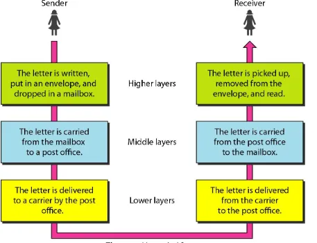
2-1 LAYERED TASKS
2.6
2-2 THE OSI MODEL
THE OSI MODEL
■
The upper OSI layers are almost always implemented in software;
lower layers are a combination of hardware and software, except for
the physical layer, which is mostly hardware.
■
The seven layers can be thought of as belonging to three
subgroups.
■
Layers 1, 2, and 3-physical, data link, and network-are the
network support layers; they deal with the physical aspects of
moving data from one device to another (such as electrical
specifications, physical connections, physical addressing, and
transport timing and reliability).
■
Layers 5, 6, and 7-session, presentation, and application-can
be thought of as the user support layers; they allow interoperability
among unrelated software systems.
■
Layer 4, the transport layer, links the two subgroups and
An Overview of the OSI Model
2-3 LAYERS IN THE OSI MODEL
In this section we briefly describe the functions of each
layer in the OSI model.
Physical Layer
Data Link Layer
Network Layer
Transport Layer
Session Layer
Presentation Layer
Application Layer
The physical layer
■
The physical layer of the OSI model defines
connector and interface specifications, as well as
the medium (cable) requirements.
2.10
The physical layer
■
Components of the physical layer include:
■• Cabling system components
■
• Adapters that connect media to physical interfaces
■• Connector design and pin assignments
■
• Hub, repeater, and patch panel specifications
■• Wireless system components
The physical layer
■ The physical layer is also concerned with the following,
❑ Physical characteristics of interfaces and medium.
■ The physical layer defines the characteristics of the interface between the
devices and the transmission medium. It also defines the type of transmission medium.
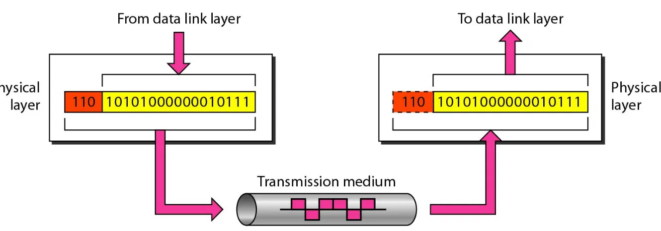
❑ Representation of bits.
■ The physical layer data consists of a stream of bits (sequence of 0s or 1s)
with no interpretation. To be transmitted, bits must be encoded into
signals--electrical or optical. The physical layer defines the type of encoding (how 0s and Is are changed to signals).
The physical layer
■
Data rate.
❑
The transmission rate-the number of bits sent each second-is also
defined by the physical layer. In other words, the physical layer
defines the duration of a bit, which is how long it lasts.
❑
Synchronization of bits.
■
The sender and receiver not only must use the same bit rate but
also must be synchronized at the bit level. In other words, the
sender and the receiver clocks must be synchronized.
❑
Line configuration.
■
The physical layer is concerned with the connection of devices to
the media. In a point-to-point configuration, two devices are
The physical layer
❑
Physical topology.
■
The physical topology defines how devices are connected to make a
network.
■
Transmission mode.
■
The physical layer also defines the direction of transmission
between two devices: simplex, half-duplex, or full-duplex.
Layer 2 – The Data Link Layer
Common networking components that function at layer 2 include:
■
Network interface cards
■
Ethernet and Token Ring switches
■Bridges
2.16
The Data Link Layer
■ Responsibilities of the data link layer include the following:
■ Framing.
■ The data link layer divides the stream of bits received from the network
layer into manageable data units called frames.
■ Physical addressing.
■ If frames are to be distributed to different systems on the network, the data
link layer adds a header to the frame to define the sender and/or receiver of the frame. If the frame is intended for a system outside the sender's
network, the receiver address is the address of the device that connects the network to the next one.
■ Flow control.
■ If the rate at which the data are absorbed by the receiver is less than the
The Data Link Layer
■
Error control.
■
The data link layer adds reliability to the physical layer by adding
mechanisms to detect and retransmit damaged or lost frames. It
also uses a mechanism to recognize duplicate frames. Error control
is normally achieved through a trailer added to the end of the
frame.
■
Access control.
■
When two or more devices are connected to the same link, data link
layer protocols are necessary to determine which device has control
over the link at any given time.
2.20
[image:20.720.84.588.101.454.2]Layer 3 – The Network Layer
■
Layer 3, the network layer of the OSI model, provides an
end-to-end logical addressing system so that a packet of
data can be routed across several layer 2 networks
(Ethernet). Note that network layer addresses can also
be referred to as logical addresses.
2.22
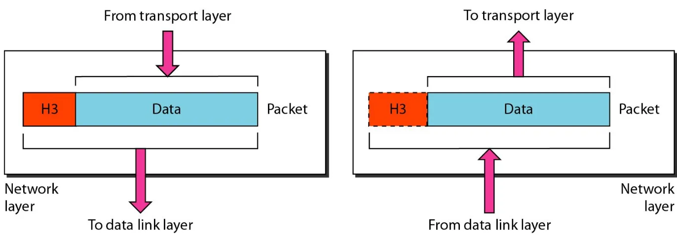
[image:22.720.15.701.147.391.2]The Network Layer
■
The network layer is responsible for the source-to-destination
delivery of a packet, possibly across multiple networks (links). The
network layer ensures that each packet gets from its point of origin
to its final destination.
■
If two systems are connected to the same link, there is usually no
2.24
[image:24.720.132.539.103.475.2]The Network Layer
■
Responsibilities of the network layer include the following:
■
Logical addressing.
■
The physical addressing implemented by the data link layer handles
the addressing problem locally. If a packet passes the network
boundary, we need another addressing system to help distinguish
the source and destination systems. The network layer adds a
header to the packet coming from the upper layer that, among
other things, includes the logical addresses of the sender and
receive.
■
Routing. When independent networks or links are connected to
Network Layer
■ Network layer is responsible for providing logical address known as IP
address. Router works on this layer. Main functions of this layer are
following:-■ Define IP address
■ Find routes based on IP address to reach its destination.
■ Data packets
■ Data packets are used to transport the user data across the network.
Protocols used by data packets are known as routed protocol. For example IP.
■ Route update packets
■ These packets are used to update the route information within
internetwork. Routers use these packets. Protocols that send route update packets are called routing protocols; for example RIP, RIPv2, EIGRP, and OSPF.
Transport layer
■
The transport layer is responsible for process-to-process delivery of
the entire message. A process is an application program running on
a host.
■
The transport layer, ensures that the whole message arrives intact
and in order, overseeing both error control and flow control at the
source-to-destination level.
2.28
Transport layer
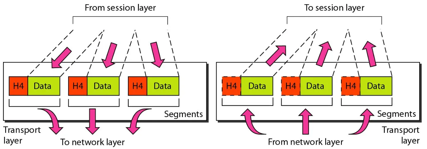
■ Responsibilities of the transport layer include the following:
■ Service-point addressing. Computers often run several programs at the
same time. For this reason, source-to-destination delivery means delivery not only from one computer to the next but also from a specific process
(running program) on one computer to a specific process (running program) on the other. The transport layer header must therefore include a type of address called a service-point address (or port address). The network layer gets each packet to the correct computer; the transport layer gets the
entire message to the correct process on that computer.
■ Segmentation and reassembly. A message is divided into transmittable
Transport layer
■ Connection control. The transport layer can be either connectionless or
connection oriented. A connectionless transport layer treats each segment as an independent packet and delivers it to the transport layer at the
destination machine. A connection oriented transport layer makes a
connection with the transport layer at the destination machine first before delivering the packets. After all the data are transferred, the connection is terminated.
■ Flow control. Like the data link layer, the transport layer is responsible for
flow control. However, flow control at this layer is performed end to end rather than across a single link.
■ Error control. Like the data link layer, the transport layer is responsible for
error control. However, error control at this layer is performed process-to process rather than across a single link. The sending transport layer makes sure that the entire message arrives at the receiving transport layer without error (damage, loss, or duplication). Error correction is usually achieved through retransmission.
Transport Layer
■ Connection management
■ Transport layer setup, maintain and tear down connections for session layer. Actual
mechanic of connection is controlled by transport layer. Transport layer use two protocols for connection management UDP and TCP.
■ UDP
■ UDP is a connection less protocol. Connection-less transmission is said to be
unreliable. Now, don't get worried about the term "unreliable" this doesn't mean that the data isn't going to get its destination; its only means that it isn't guaranteed to get its destination. Think of your options when you are sending a postcard, put it in the mailbox, and chances are good that it will get where it's supposed to go but there is no guarantee. There is always a chance of missing in the way. On the other hand, it's cheap.
■ TCP
■ TCP is a connection oriented protocol. Connection-oriented transmission is said to be
Transport Layer
■
Segmentation
■
Connection management
■
Reliable and unreliable data delivery
■
Flow control
■
Connection multiplexing
Session Layer
■
The services provided by the first three layers (physical,
data link, and network) are not sufficient for some
processes.
■
The session layer is the network dialog controller. It
establishes, maintains, and synchronizes the interaction
among communicating systems.
Session Layer
■ Specific responsibilities of the session layer include the following:
■ Dialog control. The session layer allows two systems to enter into a
dialog. It allows the communication between two processes to take place in either half duplex (one way at a time) or full-duplex (two ways at a time) mode.
■ Synchronization. The session layer allows a process to add checkpoints,
or synchronization points, to a stream of data. For example, if a system is sending a file of 2000 pages, it is advisable to insert checkpoints after every 100 pages to ensure that each 100-page unit is received and acknowledged independently. In this case, if a crash happens during the transmission of page 523, the only pages that need to be resent after system recovery are pages 501 to 523. Pages previous to 501 need not be resent. Figure 2.12 illustrates the relationship of the session layer to the transport and
presentation layers.
Presentation Layer
■ The presentation layer is concerned with the syntax and semantics of the
information exchanged between two systems.
▪ Specific responsibilities of the presentation layer include the following:
❑ Translation. The processes (running programs) in two systems are usually
exchanging information in the form of character strings, numbers, and so on. The information must be changed to bit streams before being
transmitted. Because different computers use different encoding systems, the presentation layer is responsible for interoperability between these different encoding methods. The presentation layer at the sender changes the information from its sender-dependent format into a common format. The presentation layer at the receiving machine changes the common format into its receiver-dependent format.
Presentation Layer
■
Encryption. To carry sensitive information, a system must be able
to ensure privacy. Encryption means that the sender transforms the
original information to another form and sends the resulting
message out over the network. Decryption reverses the original
process to transform the message back to its original form.
■
Compression. Data compression reduces the number of bits
contained in the information. Data compression becomes particularly
important in the transmission of multimedia such as text, audio, and
video.
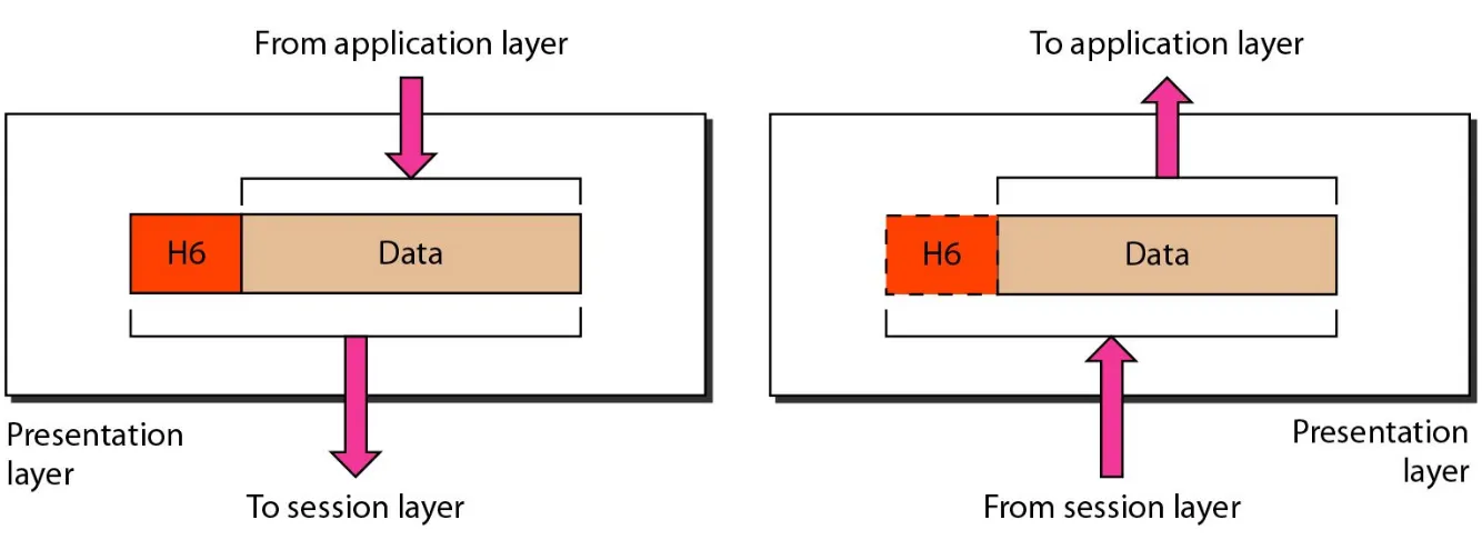
Presentation layer
■
Presentation layer prepares the data.
■
It takes data from application layer and marks it with formatting
code such as .doc, .jpg, .txt, etc. These file extensions make it
easy to realize that particular file is formatted with particular type of
application.
■
With formatting presentation layer also deals with compression and
encapsulation. It compresses (on sending computer) and
decompresses (on receiving computer) the data file.
Application layer
■ The application layer enables the user, whether human or software, to
access the network. It provides user interfaces and support for services such as electronic mail, remote file access and transfer, shared database management, and other types of distributed information services.
■ Network virtual terminal. A network virtual terminal is a software
version of a physical terminal, and it allows a user to log on to a remote host. To do so, the application creates a software emulation of a terminal at the remote host. The user's computer talks to the software terminal which, in turn, talks to the host, and vice versa.
■ File transfer, access, and management. This application allows a user
to access files in a remote host (to make changes or read data), to retrieve files from a remote computer for use in the local computer, and to manage or control files in a remote computer locally.
■ Mail services. This application provides the basis for e-mail forwarding and
storage.
■ Directory services. This application provides distributed database sources
and access for global information about various objects and services
2.40
Summary…Application Layer
■ Application layer provides platform to send and receive data over the network. All
applications and utilities that communicate with network fall in this layer. For examples
■ Browsers :- Mozilla Firefox, Internet Explorer, Google Chrome etc ■ Email clients: - Outlook Express, Mozilla Thunderbird etc.
■ FTP clients :- Filezilla, sFTP, vsFTP
■ FTP (File Transfer Protocol) — Used to transfer the files rapidly.
■ DNS (Domain Naming System) — Used to translate the name with IP address and vice versa.
■ DHCP (Dynamic Host Configuration Protocol) — Used to assign IP address and DNS information automatically to hosts.
■ Telnet— used to connect remote devices.
2.42
Data link layer
■ Main functions of data link layer are
■ Defining the Media Access Control (MAC) or hardware addresses ■ Defining the physical or hardware topology for connections
■ Defining how the network layer protocol is encapsulated in the data link layer frame ■ Providing both connectionless and connection-oriented services
■ Defines hardware (MAC) addresses as well as the communication process that occurs
within a media.
■ MAC Address
■ MAC address is a 48 bit long layer two address. It is also known as hardware
address. This address is burnt with device by manufacturing company.
■ The first six hexadecimal digits of a MAC address represent its manufacture company. ■ MAC addresses only need to be unique in a broadcast domain.
Physical Layer
■
Physical layer deals with communication media. This
layer receive frame from data link layer and convert
them in bits. It loads these bits on actual communication
media.
2-4 TCP/IP PROTOCOL SUITE
The layers in the
TCP/IP protocol suite
do not exactly
match those in the OSI model.TCP/IP is compared to
OSI, we can say that the TCP/IP protocol suite is made of
five layers:
physical
,
data link
,
network
,
transport
, and
application
.
Physical and Data Link Layers
Network Layer
2.46
2-5 ADDRESSING
Four levels of addresses are used in an internet employing
the TCP/IP protocols:
physical
,
logical
,
port
, and
specific
.
Physical Addresses
Logical Addresses
Port Addresses
Specific Addresses
2.48
Addresses in TCP/IP
■
Physical Addresses
■
The physical address, also known as the link address, is the address
of a node as defined by its LAN or WAN. It is included in the frame
used by the data link layer. It is the lowest-level address.
■
Logical Addresses
■
Logical addresses are necessary for universal communications that
are independent of underlying physical networks. The logical
addresses are designed for this purpose. A logical address in the
Internet is currently a 32-bit address that can uniquely define a host
connected to the Internet. No two publicly addressed and visible
Addresses in TCP/IP
■ Port Addresses
■ Computers are devices that can run multiple processes at the same time.
The end objective of Internet communication is a process communicating with another process. For example, computer A can communicate with
computer C by using TELNET. At the same time, computer A communicates with computer B by using the File Transfer Protocol (FTP). For these
processes to receive data simultaneously, we need a method to label the different processes. In other words, they need addresses. In the TCP/IP architecture, the label assigned to a process is called a port address.
■ Specific Addresses
■ Some applications have user-friendly addresses that are designed for that
specific address. Examples include the e-mail address (for example, faisalsiddiqui.bukc@bahria.edu.pk) and the Universal Resource Locator (URL) (for example, www.bahria.edu.pk).