17 Available online at www.ijiere.com
International Journal of Innovative and Emerging
Research in Engineering
e-ISSN: 2394 - 3343 p-ISSN: 2394 - 5494
DESIGN AND DEVELOPMENT OF VIBRATION
TEST-RIG TO STUDY BOLT PRELOAD DECAY IN
THREADED FASTENERS
Jahid P. Pinjar1
a, Abhay M.Kalje2
b1a ME (Mech-Design), N B Navale Sinhagad College of Engineering, Kegaon, Solapur, Solapur University, India.
2bAssociate Professor, N B Navale Sinhagad College of Engineering, Kegaon, Solapur, Solapur University, India.
ABSTRACT
A significant advantage of a bolted joint over other joint types, such as welded and riveted joints, is that they are capable of being dismantled. This feature however, can cause problems if it unintentionally occurs as a result of operational conditions. Such unintentional loosening, frequently called vibrational loosening. It is important for the Designer to be aware of the bolt loosening mechanisms which can operate in order to design reliable joints. This paper describes the dissertation work of design of vibration test rig which leads to the failure of fasteners by means of transverse vibration.
Keywords: Fasteners, Vibration, Loosening, Design
I. INTRODUCTION
It is widely believed that vibration causes bolt loosening. By far the most frequent cause of loosening is side sliding of the nut or bolt head relative to the joint, resulting in relative motion occurring in the threads. If this does not occur, then the bolts will not loosen, even if the joint is subjected to severe vibration. By a detailed analysis of the joint it is possible to determine the clamp force required to be provided by the bolts to prevent joint slip. Often fatigue failure is a result of the bolt self-loosening which reduces the clamp force acting on the joint. Joint slip then occurs which leads the bolt being subjected to bending loads and subsequently failing by fatigue. Pre-loaded bolts (or nuts) rotate loose, as soon as relative motion between the male and female threads takes place. This motion cancels the friction grip and originates an off torque which is proportional to the thread pitch and to the preload. The off torque rotates the screw loose, if the friction under the nut or bolt head bearing surface is overcome, by this torque. There are three common causes of the relative motion occurring in the threads,
1. Bending of parts which results in forces being induced at the friction surface.
2. If slip occurs, the head and threads will slip which can lead to loosening. Differential thermal effects caused as a result of either differences in temperature or differences in clamped materials.
3. Applied forces on the joint can lead to shifting of the joint surfaces leading to bolt loosening.
II. LITERATURE REVIEW
N.G. Pai and D.P. Hess[1] presents results of a study on failure of threaded fasteners by vibration induced loosening caused due to dynamic shear loads. Previous experimental work has revealed that fastener loosening occurs as a result of complete or localized slip at the thread and head contact surfaces. A three-dimensional finite element (FE) model is used to study details of four different loosening processes that are characterized by either complete or localized slip at the head and thread contacts. The FE model is found to be capable of adequately modelling factors that influence slip and predicting the different loosening processes. Primary factors that influence slip at fastener contacts are discussed. The results show that loosening can occur at relatively low shear loads due to the process of localized slip.
N.G. Pai and D.P. Hess [2] presents the experimental method in which they have developed the cantilever beam and nut bolt arrangement as a model to study the behaviour of the loosening effect under the action of the vibration by studying the effect of loosening in connection with the position of the fastener placement.
C.A. Cheatham, C.F. Acosta, D.P. Hess [3] presents results from an experimental investigation of loosening of threaded inserts. The tests are performed on a transverse test machine which provides transverse shear. Three different configurations are tested: insert with no secondary locking feature, insert with prevailing torque locking feature, and insert with thread adhesive locking feature. Both secondary locking features are found to provide improved resistance to loosening.
18 N.G. Pai and D.P. Hess [5] present a study on loosening of threaded fasteners subjected to dynamic shear loads. A fundamental analysis of loosening reveals that a fastener can loosen at lower loads than previously expected due to localized slip at the contact surfaces. Four different loosening processes of a screw under different conditions of slip at the head and thread contact regions are identified. Experimental results illustrating these loosening processes are presented. In addition, the minimum dynamic shear force required to initiate loosening is determined experimentally. F.M. Leon, N.G. Pai, D.P. Hess [6] presents the results from tests that investigate the effect of thread dimensional conformance of fasteners on yield and tensile strength. Test specimens include combinations of bolts and nuts within dimensional conformance as specified by ASME Standard B1.1-1992, as well as bolts with undersized pitch and major diameters and nuts with oversized pitch and minor diameters. Tensile tests were performed in accordance with ASTM F606-95b. Data from the tests show reduced yield and tensile strength for the fastener combinations with undersized pitch and major bolt diameters or oversized pitch and minor nut diameters, compared to fastener combinations within conformance. Variations in bolt pitch diameter were found to affect the yield and tensile strength by about an order of magnitude more than variations in bolt major diameter or nut pitch and minor diameters. The mean tensile strength for conforming product was found to be as much as 20% greater than the tensile strength for nonconforming product. Ingrid A. Rashquinha and Daniel P. Hess[7] shows the dynamics of threaded fastened assemblies represent a highly nonlinear constrained vibration problem that is nontrivial, but of considerable practical importance. In this paper, a dynamic model of a fastened assembly is developed which incorporates a dynamic fastener model with dynamic structural component models. Simulations from the model reveal that fastener placement in assemblies can be optimized to reduce vibration-induced loosening. This result is fundamentally significant since the current practice for placement and orientation of fasteners in assemblies is generally based on convenience or static load and strength considerations, and not dynamic considerations.
III. DESIGN OF PARTS OF VIBRATION TEST RIG.
Preloaded fasteners self-loosen when relative movement occurs between the mating threads and the fasteners bearing surface. Such relative movement will occurs when the transverse force acting on the joint is larger than the frictional resisting force generated by the bolts preload. Under repeated transverse movements this mechanism can completely loosen fasteners. Determination of forces and utilizing system of forces to determine the linkage dimensions of critical parts of drive. 3-D modelling of set-up will be done using Unigraphix Nx-8.0 and CAE of critical component and meshing using ANSYS Work-bench 14.5. The mechanism of this project is similar to Junker’s vibration test rig which modified to three frequency sets by means of a belt & pulley system which is coupled with a jockey & eccentric so that shaft rotates eccentrically and the plate is reciprocating with the help of spring. The detailed analysis & design procedure is explained as follows.
A. Selection of Motor.
The motor is three phase motor with a 0.5 Hp having speed of 1440 RPM.The torque produced by this motor is calculated as follows,
𝑇 =60 𝑃
2𝜋𝑁 ….. (1)
The calculated torque is T = 2.45 Nm= 2.45 x 10³ N.mm.
Considering 100 % overload T Design = 2T = 4.90 x 10³ N.mm.
B. Design of Motor shaft and Main Shaft.
There are two shaft one is motor shaft & other is main shaft[9]. The first design is of motor shaft. It is considered the shaft is subjected to both bending & twisting moment. From PSG design data book we have the Sut= 1100 N/mm2 and Syt = 880 N/mm2 .
The permissible shear stress is calculated as ,
𝜏 = 0.30 𝑆𝑦𝑡 = 264 𝑁/𝑚𝑚2 and 𝜏 = 0.18 𝑆𝑢𝑡 = 198 𝑁/𝑚𝑚2
Considering the minimum permissible shear stress of the above values as 198 N/mm2.
Now consider the shaft is under pure torsion hence we have to find the required diameter as follows, 𝑇𝐷𝑒𝑠𝑖𝑔𝑛=
𝜋
16 𝜏 𝑑
3….. (2)
19 “Fig 1.Free Body Diagram for design of Main shaft.”[9]
The eccentric load W is placed at a distance of 62 mm from A and 67 mm from B. Calculating for the reaction forces we have RB=25.76 N and RA=23.8 N.The maximum bending moment M occurs at point B 1725.92
N.mm . The equivalent torque is as follows,
𝑇𝐸= √𝑀2+ 𝑇𝐷𝑒𝑠𝑖𝑔𝑚2= 2.996 × 10³𝑁 𝑚𝑚 ≈ 3000 𝑁 𝑚𝑚 …..(3)
Now for shaft design, 𝑇𝐸 =
𝜋
16 𝜏 𝑑
3 …..(4)
3000 = 𝜋
16 𝜏 16
3 ….. (5)
𝜏 = 77.166 N/mm2 .
The above value is less than 198 N/mm2. Hence the designed diameter 16 mm shows safe design for torsion
load value.
The maximum bending moment M occurs at point C . Hence to calculate the diameter of main shaft we have to use the maximum normal stress theory. We have,
𝑀𝐸=
1
2(𝑀 + 𝑇𝐸) = 3.0375 × 10
3𝑁𝑚𝑚 ….(6)
Now check for bending stress, and assuming trial design for main shaft diameter, D=30 mm
𝑀𝐸=
𝜋
32𝜎𝑏 𝑚𝑎𝑥𝐷 3
𝜎𝑏 𝑚𝑎𝑥=1.146 N/mm2 ... Less than permissible shear stress value as 198 N/mm2. Hence design is safe.
The same diameter will act as a internal diameter for eccentric.
C. Design of Eccentric.
The design of eccentric is done in such a way that it will convert rotary motion of shaft into the reciprocating motion of the movable plate which result in the loosening of the fastener. The eccentric has outside diameter of 50 mm & internal diameter of 30 mm. Now we have to check for the safe design of the diameters as they are under torsional shear stress[9].
We have,
𝑇𝐸= 𝜋 16 𝜏
𝑑𝑜4−𝑑𝑖4
𝑑𝑜 ….. (7)
3000 = 𝜋
16 𝜏
504− 304
50
𝜏 = 0.1404 N/mm2 ... Less than permissible shear stress value as 198 N/mm2. Hence design of eccentric is safe.
IV.ANALYSISOFCOMPONENTS
The analysis procedure is as follows ,
1. Modelling of the geometry is being done in Unigraphics software. 2. The generated IGES file is exported to ANSYS workbench
3. The model is discretized into finite elements by triangular mesh elements. 4. Applying boundary conditions and loads.
5. Solve the problem.
6. Post processing the result to get nodal solution like equivalent stress.
The analysis is done for only the critical components. A. Analysis of Eccentric:
The analysis of the eccentric is as tabulated below.
W=49.6 N
20 Table 1. Analysis of Eccentric
GEOMETRY MESHING LOADING POST PROCESSING
RESULTS
As maximum induced stress (7.3N/mm2) < allowable stress (108 N/mm2) the Eccentric is safe under torsional failure
B. Analysis of Leaf Spring
The analysis of the leaf spring is as tabulated below. While loading condition the load is applied considering the eccentric loading as 49.6 N
Table 2. Analysis of Eccentric
GEOMETRY MESHING LOADING POST PROCESSING RESULTS
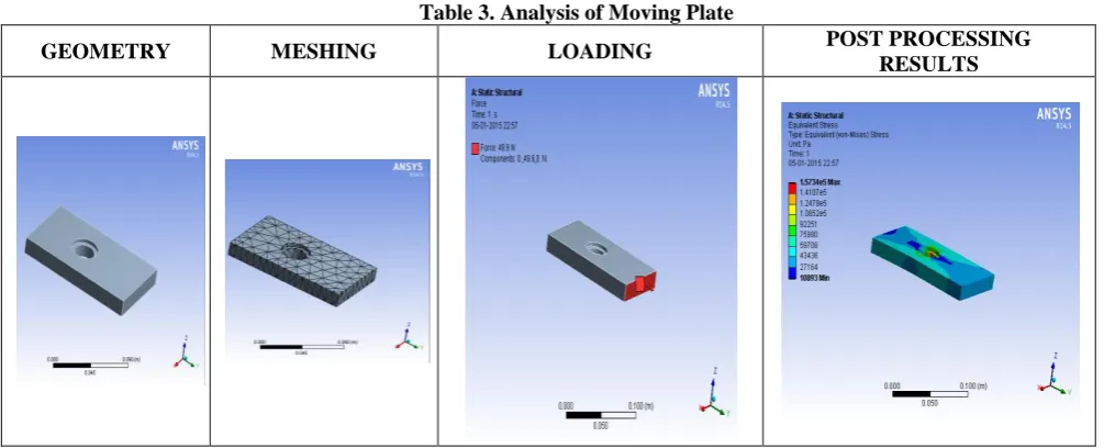
C. Analysis of Moving Plate
Table 3. Analysis of Moving Plate
GEOMETRY MESHING LOADING POST PROCESSING
RESULTS
21
V. CONCLUSIONS
From the above theoretical design & analysis of the components it is found that the design of the critical components is safe. Hence one can easily manufacture the components by considering the above dimensions.
REFERENCES
[1] N.G.Pai and D.P. Hess, “Three dimensional finite element analysis of threaded fastener loosening due to dynamic shear load”, Engineering Failure Analysis, Volume 9(2002) pp-383-402.
[2] N.G.Pai and D.P. Hess, “Influence on fastener placement on vibration induced loosening”, Journal of Sound and Vibration, Volume 268(2003) pp-617-626.
[3] C.A.Cheatham, C.F.Acosta,D.P.Hess “Test and analysis of secondary locking features in threaded inserts ”, Engineering Failure Analysis, Volume 16 (2009) pp 39-57.
[4] R.I.Zadokas and D.P.R.Kokatam, “Investigation of axial stiffness of bolt using a three dimensional finite element model” Journal of Sound and Vibration, Volume 246(2)(2001) pp-349-373.
[5] N.G.Pai and D.P. Hess, “Experimental study of loosening of threaded fasteners due to dynamic shear load”, Journal of Sound and Vibration, Volume 253(3)(2002) pp-585-602.
[6] F.M.Leon,N.G.Pai and D.P. Hess, “Three dimensional finite element analysis of threaded fastener loosening due to dynamic shear load”, Engineering Failure Analysis,Volume 8(2001) pp-49-56.
[7] I.A.Rashquinha and D.P. Hess, “Modelling nonliner dynamics of bolted assembelies”, Applied Mathematical Modelling,Volume 21(1997) pp-801-809.
[8] Satoshi Izumi,Takashi Yokoyama,Atsushi Iwasaki,Shinsuke Sakai “Three dimensional analysis of tightening and loosening mechanism of threadaed fastener”, Engineering Failure Analysis,Volume 12(2005) pp-604-615. [9] V.B.Bhandari, “Design Of machine elements”, Tata Mc Graw Hill ,2005.