Design, construction and performance evaluation of a reaper for
small farms (a case study: Iran)
Ebrahim Zareishahamat, Samsollah Abdollah Pour
*, Mohammadali Maysami
(Department of Biosystems Engineering, Faculty of Agriculture, University of Tabriz, Tabriz, Iran)
Abstract: Annually about 0.2 million ha of farms in Iran country are not harvested. The main reason of not harvested area is
the lack of a suitable machine for harvesting small and rough fields. To prevent damage caused by not harvested area, a machine with a 1 m length cutter bar and 4.85 kW engine that was suitable for small farms, having high reliability and maneuverability on rough terrain was designed, fabricated and evaluated. The results of machine performance evaluation showed that forward speed has a significant effect on field efficiency and crop losses. Increasing the machine forward speed caused decreasing the field efficiency and increasing crop losses. The forward speed of 0.5 m s-1 had the lowest crop losses
and was less exhausting and had the maximum energy saved compared to 1 and 1.5 m s-1. Therefore, the forward speed of
0.5 m s-1 had the best result. Results of cost analysis showed that the total cost of machine was 20 $ ha-1. The cost of manual
harvesting was 154 $ ha-1. The minimum justified ownership area for the machine was 1.3 ha which is appropriate for
agricultural systems with small farms.
Keywords: design for small farms, economic analysis, energy saved, forage barley, reaper-windrower
Citation: Zareishahamat, E., S. Abdollah Pour, M. Maysami. 2019. Design, construction and performance evaluation of a
reaper for small farms (a case study: Iran). Agricultural Engineering International: CIGR Journal, 21(3): 104–113.
1 Introduction
Due to droughts and lack of water resources, planting of forage crops with little water requirement is very promising. Barley is one of these products. There are three common methods of barley harvesting, namely: grain harvesting, dry forage harvesting and silage forage harvesting. If the purpose is barley forage harvesting at the early dough stage GS (A decimal code for the growth stages of cereals)-83 (Zadoks et al., 1974), the product will probably have the highest quality and quantity. The yield of barley with the highest amount of dry matter was 5,670 kg ha-1 and the best way to commercial use from barley is harvesting it as dry forage and at the pasty stage of grain (Ghanbari et al., 2007). The common method of dry forage harvesting is the use of a self-propelled or tractor-drawn mower. Existing mowers are expensive and
Received date: 2018-10-12 Accepted date: 2019-01-26
*Corresponding author: Samsollah Abdollahour, Associate
professor, Department of Biosystems Engineering, Faculty of Agriculture, University of Tabriz, Tabriz, Iran. postal number:5166616471. Tel: 984133392776. Fax: 984133356007. Email: [email protected]
have a high level of justified ownership area. The minimum ownership justification area for CLAAS and John Deere combine harvesters, self-propelled mower, MF 285 and MF 399 tractors are 215, 255, 42, 14.3 and 20 ha, respectively (Shiralinejad and Moghaddasi, 2010), but the most of the operation units in Iran are small and scattered and also, shared use of machinery is not common which causes many problems. Therefore, the use of recent machines for these units is not economical. Also, the maneuverability of these devices in small lands is very low.
Due to some reasons, the not harvested area of barley is about 11% of the cultivated area, equivalent to 0.2 million ha (Anonymous, 2009). The main reason of not harvested area is the lack of a suitable machine for harvesting small and rough fields. Therefore, it is necessary to design and construct a suitable machine for small and scattered farms in Iran.
Chavan et al. (2015) stated that using a manual operated reaper is more affordable comparing with traditional method. Laukik et al. (2014) concluded that the harvesting cost using a compact harvester is considerably low as compared to manual harvesting.
About 10%-11% of the cultivated land of wheat and barley are not harvested each year because of the distribution of farms land in Iran, which are often widespread, small and rough. Recent drought and the problems faced by farmers in supplying forage to livestock units will be considered the design and construction of an economical and efficient machine for working in small farms.
2 Materials and methods
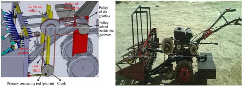
In the current study, the effective parameters in the design and construction of different parts of a forage barley reaper were considered. A reaper machine was constructed and then, it was evaluated to find out if it worked properly according to the parameters. The present machine was constructed in Hamedan city and was tested in Heyran village of Hamedan province of Iran.
2.1 Crank design mechanism
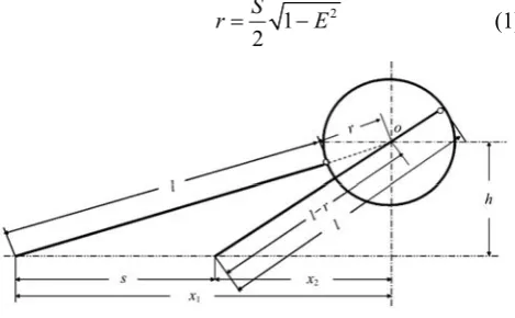
In the current research, a plane crank driving system was used because of its simplicity in construction, availability of components and affordability, comparing with other methods. In the designed machine, there must be employed an asymmetric crank system. In such a system the stroke of the knife bar ‘S’ is not equal to a double crank radius. Equation (1) shows the relation between radius ‘r’ of cranks (m), knife stroke ‘S’ (m) and eccentricity ‘E’ (dimensionless) of the system. ‘l’ is pitman length (m) and ‘h’ is crank height above the cutting plane (m) that show in the Figure 1 (Kariafojski and Karwowski, 1976).
2
1 2
S
r= −E (1)
Figure 1 Extreme pitman positions
2.2 Conveying unit
There are different methods for crop transfer. Vertical transfer has the minimum losses and reaped crop lies in a windrow which could be easily picked up by labors.
2.3 Engine selection
To select an appropriate engine for the machine, at first the power requirements of machine were calculated. The power requirements included the followings: 2.3.1 Power required to cutter bar mechanisms
Power required to cutter bar mechanisms was calculated by Equation (2) (Srivastava et al., 2006),
1 4
6 10
ave bu cut
F X f
P = × ×
× (2)
where, P1 = power for cutting (kW); Fave = average
cutting force (kN); Xbu = depth of material at initial
contact with knife (mm); fcut = cutting frequency (cuts
min-1),
fcut=Wi×V×n×60 (3)
where, Wi = cutting width (m); V= forward speed (m s-1); n = number of plant was 250 plants m-2.
2.3.2 Power required for conveying unit
This power was related to windrowing of cut crop, and this power is required to move the chains and lugs, rotate the axes and move the cut crop. The average weight of each barley stem at this stage was 4.5 g.
Cut area per time (m2 s-1) = cutting width (m) × forward speed (m s-1)
Number of cut stems per time (stems s-1) = number of cut stems per area (stems m-2) × cut area per time (m2 s-1)
Mass of cut crop per time (kg s-1) = number of cut stems per time (stems s-1) × mass of one stem (kg)
Power requirement for transforming in the cutting width (N.m s-1) = mass of cut crop per time (kg s-1) × g (m s-2)
The above calculated power was the power needed to move the cut crop in a unit of time. Some power was used for moving the lugs and rotational axes of the windrow mechanism in an idle mode. In order to ensure that the calculated power would be enough, a confidence coefficient of 2 was considered.
2.3.3 Power losses
P3=R×V (4) where, P3=power losses (kW); R=rolling resistance force (kN); V=forward speed (m s-1).
Rolling resistance force was calculated from Equation (5):
R=ρ×W (5) where, R=rolling resistance force (kN); ρ=coefficient of rolling resistance and W = weight of machine (was 2200 N). Soil texture of the tested farms was loamy and the tyre diameter was 0.4 m. Therefore, the rolling resistance coefficient was 0.33 (Macmillan, 2010).
2.3.4 Power required to moving the machine on it’s forward speed
This power was obtained from Equation (6),
P4=Ftraction×V (6)
where, Ftraction=net traction force (N); V=forward speed
(m s-1).
In order to calculate net traction force Equation (7) was used:
Ftraction=H– R (7)
where, Ftraction=net traction force (N); H=gross traction
force (N) and R=rolling resistance force (N).
The Equation (8) is also available for gross traction force:
H=A×C+W×tanφ (8)
where, H=gross traction force (N); A=contact area of tyre with soil (mm2); C=cohesion for semi harsh loam soils which is 0.25-0.3 and here was taken 0.27 (kg mm-2);
W=weight of machine (N) and φ=angle of internal friction for semi harsh loam soils which is 22°-26° that here was taken 24° (Bernacki et al., 1972). After calculating the gross traction force and rolling resistance from Equation (5) by placing in the relation (7), the net traction force was obtained.
2.3.5 Total power
The total power requirement for engine, therefore, was the sum of the above mentioned powers through the Equation (9):
1 2 3 4
e
p
p p p p
p
η
+ + +
= (9)
where, Pe was the total power requirement for the engine
(kW) and ɳp was the power transmission efficiency.
Transmission efficiency of gears is about 98% per pair of gears and the efficiency of V-belt drive ranges from 70%
to 96% (Budynas and Nisbett, 2011). So, an available engine that could supply this power was selected.
2.4 Transmission selection
In selecting of the power transmission, some parameter such as: type of available gearbox, input to output ratio, power range, physical constraints and prices should be considered. The diagram of power transmission system is shown in Figure 2.
Figure 2 Diagram of power transmission system
2.5 Relations between forward speeds, cutter bar
speed and chain conveyor
The operator has to walk behind the machine, so the forward speed should be enough comfort. The best speed for operator walking behind the machine in the field was achieved to be 1 m s-1. Cutting speed should be higher than the forward speed, if not stalks will be flattened and crushed accompanied by large resistive force. So, specified speed of the cutter bar shaft (in rpm) should be justified over the forward speed (Sharmin, 2014).
VC≥V (10)
The rotational speed of the driver pulley of the cutter bar was achieved through Equation (11) (Devani and Pandey, 1985).
30 C C
V N
S
⋅
= (11)
where, NC = rotational speed of driver pulley of cutter bar
(rpm); VC = cutting speed (m s-1); S=stroke length of the
cutter bar (m). In this research stroke length of the cutter bar was 76 mm. Therefore, assuming the above values, the amount of NC was obtained to be 592 rpm.
2.6 Lug speed (VL) and lug spacing
speed was given 1.5 times of the cutting speed to avoid possibility of clogging due to higher crop density or vegetative growth. Lug spacing has a relation with star wheel diameter and number of wings of the star wheel (Sharmin, 2014).
. o
W
π D
Lug spacing N
×
= (12)
where, Do =outer diameter of star wheel (m); NW=
number of wings (here 7).
In the star wheel there were seven wings and lug spacing was calculated as 94 mm. The lug should be placed in such a way that it can give motion to the star wheel without any slippage.
2.7 Effective parameters in star wheel design
Some parameters must be considered in star wheel design such as: crop varieties and speed of star wheel which was equal to VS.cosα and this should be greater than the forward velocity of the machine, so the star wheel could gather crops toward the cutter bar (Devani and Pandey, 1985).
cos 1.026 s
m
V α
V
×
= (13)
where, Vs =speed of star wheel m s-1; Vm =forward speed
m s-1 and α=angle of star wheel with horizon.
2.8 Calculation of the force required on the handles
In order to calculate the force required on the handles, the following relationship was obtained. The static balancing of the reaper was shown in Figure 3.
0 0
0 0
0 500 20 1050
x
y
R C
F F
F W R W R
M W W P
∑ = → ∑ =
∑ = → − = → =
∑ = → × = × + ×
where, WR = Weight of reaper (45 kg); WC = Counter
weight (65 kg); P=effort on handle.
Figure 3 Static balancing of the reaper
2.9 Performance evaluation
The performance evaluation of machine was done in 2017/2018, a randomized complete block design used to analyzing the effects of three levels of forward speed (0.5, 1 and 1.5 m s-1) with three replications on machine field efficiency and forage barley yield losses. Therefore, nine plots with a size of 20×25 square meters were selected. The farms were uniform and their soil was loam. The test was done in May 2018. Plant height, labor requirement, theoretical and effective field capacity, field efficiency, crop losses, net energy gain and fuel consumption during the field operation were recorded or calculated as following formulae (Mehetre et al., 2014):
2.9.1 Theoretical field capacity, effective field capacity and field efficiency
Theoretical field capacity, effective field capacity and field efficiency were obtained from below Equation:
10
i t
WV
C = (14)
where, Ct =theoretical field capacity (ha h-1); Wi =rated
width of cutter bar (m); V=forward speed (km h-1).
h a
A C
T
= (15)
where, Ca = effective field capacity (ha h-1); Ct =
theoretical field capacity (ha h-1); Ah =total area harvested
(ha); T=operating time (h); ɳ=field efficiency (%).
100
a
t C η
C
= × (16)
2.9.2 Net energy gain
Net energy gain = output energy (MJ ha-1) –
input energy (MJ ha-1) (17) In comparison with two speeds up, net energy gain is the difference between the input and output energy. Output energy was the energy gained because of the reduction in crop losses (High Heating Value based) and input energy is the energy related to fuel consumption. Energy equivalent of gasoline fuel was 47.8 (MJ L-1) (Yousefi et al., 2016). And energy equivalent of the forage barley obtained from calorimeter bomb in advanced nutrition lab was 25.28 MJ kg-1.
2.9.3 Crop losses
100
gt go
losses
H H
H
Y
−
= × (18)
where, Hlosses=Harvesting losses (%); Hgt=losses during
and after harvesting (kg m-1); Hgo=natural losses occur
before harvesting (kg m-1); Y=total yield (kg m-1). 2.9.4 Cost analysis
In order to analysis of machine operation costs, we need to know about cost details that are included two parts, fixed and variable cost item. Fixed costs consisted of depreciation, annual interest on investment, tax, insurance and shelter. Variable costs consisted of repair and maintenance costs, labor cost, fuel cost and lubrication cost. In order to calculating the depreciation cost, straight line depreciation was assumed and the following equation was used (Hunt, 2015).
p v
p
P S
D L
−
= (19)
where, D is depreciation ($ year-1); Pp is purchase price of
the reaper equal to 1111 $; Sv is salvage value equal to
444 $ and Lp is ownership period for 10 year.
‘I’ is annual interest on investment that calculated by following equation.
( )
2
p v
P S i
I = + × (20)
where, I is annual interest on investment ($ year-1) and ‘i’ is annual interest rate here 15%. Tax, insurance and shelter are not obligatory and necessary in Iran. Annual fixed cost was calculated as below equation. FAC is annual fixed cost ($ year-1).
FAC = Depreciation + Interest on investment +
Tax+ insurance + shelter (21) Repair and maintenance costs were used as recommended by ASAE standard (2000).
2 1
& [ ]
1000
RF p
t
R M =P ×RF× (22)
where, R&M is annual repair and maintenance cost ($ year-1); RF1 and RF2 are repair coefficient equal to 0.26 and 1.6, respectively (ASAE standard, 2000), and ‘t’ is annual use of machine (h year-1). The harvesting season is 30 days at year and 9 hours a day, so annually use of 270 hours were considered for this machine. Other variable costs were driver payment and fuel cost that were calculated by below Equations:
L=Plabor×N (23)
Ffuel=Pfuel×FC (24)
where, L is driver payment ($ h-1); Plabor is labor payment
($ h-1); N= Man-hours per hectare; F
fuel is fuel cost ($ h-1); Pfuel is fuel price ($ L-1); FC= fuel consumption (L h-1)
that before starting the harvesting operation in the test plot, the fuel tank of the machine was filled up to its full. The quantity of fuel required to fill the tank fully after harvesting the plot was measured to determine the quantity of fuel consumed for reaping the test plot. Oil cost was considered as 25% of fuel cost (Zami et al., 2014).
Annual operating cost is sum of fixed and variable cost that was calculated by following Equation
& h[ ]
fixed fuel
A
AC F R M L O F
Ca
= + + + + (25)
where, AC is annual operating cost ($ year-1); Ffuel is fuel
cost ($ h-1); Ffixed =fixed costs of machine ($ year-1); Ah is
annual area harvested (ha); Ca is effective field capacity of the reaper (ha h-1); R&M is repair and maintenance cost ($ year-1).
2.10 Break-even analysis
The break-even point, the area that a machine has to work per year in order to justify machined owning, was determined by the following Equation (Alizadeh et al., 2007):
fixed
a m
F B
V V
=
− (26)
where, B=Break–even point (ha year-1); Ffixed =fixed
costs of machine ($ year-1); Va =variable costs for manual
method ($ ha-1); V
m =variable costs for machinery method
($ ha-1).
3 Results and discussions
With interview by operators, it was found that the normal length of the conventional mower was 1.2 m which was somewhat more causing problems such as: power scarcity of the BCS mowers and breakage of the output gearbox shaft connected to the cutter bar. Therefore the length of cutting unit was considered to be 1 m and had 13 guards and 13 cutting blades attached to the main frame. The radius of the crank mechanism obtained from the Equation (1) was: E=h l-1, h=244 mm,
3.1 Conveying unit
The conveying unit had lug chain conveyor, sprocket, star wheel, row divider and guide spring. This reaper had three row dividers. It is similar to conveying unit constructed by Devani and Pandey (1985).
3.2 Engine selection
The results of calculation showed that total power required for the current machine was equal to 1.56 kW. Available diesel or gasoline engines in the Iranian market have a power range of 4.1 to 13.8 kW. Considering the required power, engine markets and economical cost, a Weima gasoline engine model WM 168FB with 4.8 kW at 3600 rpm was used. It is similar to power source used by Mehetre et al. (2014) that was 4.47 kW diesel engines.
3.3 Gearbox
There were two types of gearboxes available on the market. First one, were connected directly to the output shaft of engine. And the second, whose input shaft was powered by a pulley and belt. The price of the first type gearbox was more expensive and the installation of this gearbox on the engine needed a lot of technical
considerations. So, the second gearbox was selected. The gearbox had two forward and one reverse gears shown in Figure 4.
Figure 4 Gear box for power transmission to the wheel axel
3.4 Transforming power to the cutter bar
Power transmitted to the cutter bar through the input shaft of the gearbox. The rotation speed of the input shaft of the gearbox (at rated speed of engine) was 2000 rpm. The power was transmitted from the gearbox shaft through a pulley added beside the gearbox pulley with a bolt and a nut. Figure 5 showed the schematic of power transforming from engine to the cutter bar.
Figure 5 Schematic of power transmission from the engine to the cutter bar
3.5 Speed of star wheel
According to equation the speed of star wheel was calculated as follow,
1
1.026
cos cos18 0.95
1.07 m s 1
s s s
s
m m
V α V V
V
V V
−
=
× = × °= × ⇒ =
Taking Vs =1.1 m s-1.
The star wheel was driven by the vertical chain conveyor with lugs.
3.6 Force required on the handles
Required force to effort on handle was obtained
according to below:
0 400 200 1050
45 500 65 200 1050 22500 13000 1050
9500 9 kg 1050
M WR WC P
p p
p
∑ = → × = × + ×
× = × + ×
= +
= =
3.7 Machine specification
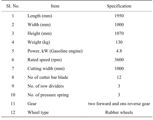
Several specifications of the constructed machine are shown in Table 1.
Table 1 The dimensional specifications of the reaper
SI. No. Item Specification 1 Length (mm) 1950 2 Width (mm) 1000 3 Height (mm) 1070 4 Weight (kg) 130 5 Power, kW (Gasoline engine) 4.8 6 Rated speed (rpm) 3600 7 Cutting width (mm) 1000 8 No of cutter bar blade 12 9 No. of row dividers 3 10 No. of pressure spring 3
11 Gear two forward and ons reverse gear 12 Wheel type Rubber wheels
Machine specification constructed in the current study was similar to machine specification designed by Devani and Pandey (1985), Rahman et al. (2004), El-Sharabasy (2006), Celik (2006), Dange and Thakare (2010), Murumkar et al. (2014), Laukik et al. (2014), and Chavan et al. (2015). The current machine had gasoline engine and was suitable for forage wheat and barley harvesting and that was the main difference between the current and previous constructed machine.
3.8 Performance evaluation of machine
The machine was used for harvesting forage barley at GS-83. The average value of some of the parameters including effective cut width, forward speed, total operation time, theoretical field capacity, effective field capacity, field efficiency, fuel consumption and cutting height above the ground were shown in Table 2.
Table 2 Performance evaluation of the reaper
Place Effective cut width (m)
Forward speed
(m s-1) Total operation time (min ha-1) capacity (ha hTheatrical field -1) capacity (ha hEffective field -1) efficiency Field Av.fuel consumption(L h-1) Cutting height (mm)
0.5 520 0.18 0.12 0.61 2
1 360 0.36 0.16 0.44 1.5
Rain-fed farm for Barley 1
1.5 310 0.54 0.19 0.35 2
50
Result of fuel consumption of the machine showed that the current machine consumed 1.5 L h-1 (at forward speed of 1 m s-1) that was more than Chinese and Bangladesh Rice Research Institute (BRRI) reapers that were 0.727 and 0.826L h-1, respectively (Zami et al., 2014). The cutting widths of Chinese and BRRI reapers were 1.2 m and both of them had a diesel engine and they were the reasons of difference between fuel consumption. Murumkar et al. (2014) showed that the actual field capacity of the self propelled vertical conveyor reaper was 0.3 ha h-1 with a field efficiency of 72%.
3.9 Effect of machine forward speed on field
efficiency and crop losses
The results of variance analysis for the effects of block and forward speed on the field efficiency are given in Table 3.
The results of variance analysis showed that the effect of block and forward speed had a significant effect on the field efficiency in 5% and 1% probability level, respectively. The Duncan’s multiple range tests for field efficiency showed that the difference between means at speed of 0.5 m s-1 with other speeds was significant, but
the difference between speed of 1 and 1.5 m s-1 was not significant. The results of variance analysis for the effects of forward speed on crop losses are given in Table 4.
Table 3 Variance analysis of effective factors on the field
efficiency
Source of variation Degree of freedom Sum of square Mean square Block 2 0. 018 0. 009* Forward speed 2 0.014 0. 07** Experimental error 4 0. 005 0.001
Total 8 0.016 Note: %SS values without symbol are not significant, ‘*’ significant at P<0.05
and ‘**’ significant at P<0.01.
Table 4 Variance analysis of effective factors on the crop
losses
Source of variation Degree of freedom Sum of square Mean Square Forward speed 2 11.05 5.27** Experimental error 6 2.66 0.44
Total 8 13.72 Note: %SS values without symbol are not significant, ‘*’ significant at P<0.05 and ‘**’ significant at P<0.01.
losses means at speed of 1.5 m s-1 with other speeds were significant, but the difference between speed of 0.5 and 1 m s-1 was not significant. The result of crop losses of current machine at the forward speed of is equal to 3.8%, while Sharmin (2014) showed that grain losses were 2.43%. Singh et al. (1988) found that grain losses for reaper were 4%. Devani and Pandey (1985) stated that the total harvesting losses for reaper was in the range of 4% to 6% of grain yield.
Amount of average field efficiency and crop losses at different forward speed are shown in Figure 6. This figure showed that by increasing in forward speed the field efficiency was decreased and crop losses was increased respectively. The linear regression model was Y = –0.29×(X) + 0.81 with R2=0.88 for field efficiency and Y
= 2.5×(X) + 1.94 with R2 =0.84 for crop losses. The ‘X’ assigns forward speed (m s-1).
Figure 6 Amount of average crop losses and field efficiency at different forward speed
3.10 Energy consumption of different forward speeds
The results of energy comparison between forward speeds showed that forward speed of 0.5 m s-1 had 0.33% crop losses less than that of 1 m s-1 equal to 26.4 kg ha-1 (the total yield was 8000 kg ha-1) so, this is equal to 672 MJ ha-1 (High Heat Value based), while in 0.5 m s-1 the machine was consuming 7.29 L ha-1 more gasoline fuel than that of 1 m s-1. This difference in gasoline consumption is equal to 348.5 MJ ha-1 so, the speed of 0.5 m s-1 saves 323.4 MJ ha-1 energy compared to 1 m s-1. The forward speed of 0.5 m s-1 saves 4746 MJ ha-1 energy than 1.5 m s-1 at the same way. According to the results of this research by decreasing the forward speed of the machine, the field efficiency was increased and the crop losses were decreased. The energy saved at this speed was more than the other speed. Moving at the speed of 0.5 m s- 1 was less exhausting and more ergonomic for the operators. Therefore, the forward speed of 0.5 m s-1
had the best results.
3.11 Cost analysis
The amount of total costs of the reaper including fixed costs and variable costs are shown in Table 5. The annual harvested area was 30 ha, so, the total cost was 20 $ ha-1, fixed cost was 6 $ ha-1 and variable cost was 14 $ ha-1, respectively.
Table 5 Total costs of the reaper
Cost items $ year-1
A) Fixed costs
1-Depreciation 66 2-Interest 115.5 3-Taxes, insurance and shelter 0
4-Total fixed cost 181.5 B)Variable cost
1-Fuel 89.1 2-Oil 22.27 3-Labor 297 4-Repair & maintenance 35.2
5-Total variable cost 443.5 Total cost of harvesting 625
sickles was 43.9 EGP ha-1 for wheat and 52.9 EGP ha-1 for rice. Therefore, the mower could save about 62% in the case of wheat crop and about 63% in the case of rice crop.
4 Conclusion
One of the most important reasons for non harvested area is the lack of a proper harvesting machine. The solution to this problem is to design and construction a reaper for harvesting barley at the forage stage. Alternative solutions to this problem were the use of manual labor, BCS harvesters and the use of combine harvesters. Difficulties in using the manual harvesting method: costly and tedious to operate. The problem of using BCS and combine harvester was also mismatch between the level of ownership of those machines and the level of ownership of the smallholder farmers. The level of ownership justified for the present machine was 1.1 hectares, and showed that the share of operating units below 2 hectares is about 50% of the total operating units, so the present machine is a suitable option for Iranian agricultural conditions.
Technical (fuel consumption, field efficiency and crop losses), economic (level of ownership justification) and energy (Net energy value) evaluation of constructed machine in the present study showed that this machine had special advantages and was suitable for low operation units in Iran.
References
Alizadeh, M. R., I. Bagheri, and M. H. Payman. 2007. Evaluation of a rice reaper used for rapeseed harvesting. American-Eurasian Journal of Agricultural & Environmental Science, 2(4): 388–397.
Anonymous. 2009. Results of sample survey design for wheat and barley in Iran. Deputy Director of Planning Affairs, Economic and International Office of Statistics and Information Technology of Iran's Agriculture Ministry.
ASAE Standards. 2000. Agricultural Machinery Management. Michigan State, USA: ASAE.
Bernacki, H., J. Haman, and G. Kanafojski. 1972. Agricultural machines, theory and construction, vol. 1. Washington DC: US Department of Agriculture and the National Science Foundation.
Budynas, R. G., and J. K. Nisbett, 2011. Shigley’s Mechanical Engineering Design. 9th ed. New York: McGraw-Hill.
Chavan, P. B., D. K. Patil, and D. S. Dhondge. 2015. Design and development of manually operated reaper. IOSR Journal of Mechanical and Civil Engineering, 12(3): 15–22.
Celik, A. 2006. Design and operating characteristics of a push type cutter bar mower. Canadian Biosystems Engineering, 48(2): 23–27.
Devani, R. S., and M. M. Pandey. 1985. Design development and evaluation of vertical conveyor reaper windrower. AMA Agricultural Mechanization in Asia, Africa and Latin America, 16(2): 41–52.
Dange, A. R., and S. K. Thakare. 2010. Development and performance evaluation of tractor front mounted pigeon pea stem cutter. Iranica Journal of Energy & Environment, 1(3): 200–204.
El-Danasory, M. M. 1987. Intensifying the use of mowers under Egyptian conditions. M.S. thesis, Egypt: Cairo University, Cairo.
El-Sahar, E. A. 1988. Design of harvester appropriate for Egyptian agriculture. M.S. thesis, Egypt: Ain Shams University, Cairo. El-Sharabasy, M. M. A. 2006. Construction and manufacture a
self-propelled machine suits for cutting some grain crops to minimize losses and maximize efficiency. Misr Journal of Agricultural Engineering, 23(3): 509–531.
Ghanbari, A., S. Mohaddeth, A. Feizi, R. M. Abazari, and H. Fazaeli. 2007. Economic evaluation of three methods of full forage production in livestock feed.In 6th Iranian Agriculture Economics, 67–75. Mashhad: Iranian Agricultural Economics Association.
Hanna, G. B., and A. E. Suliman. 1986. Appropriate harvesting equipment for small Egyptian farms. Misr Journal of Agricultural Engineering, 3(1): 58–72.
Hunt, D. 2015. Farm Power and Machinery Management. 11th ed. pp.326. Illinois: Waveland Press, Inc.
Kariafojski, C., and T. Karwowski. 1976. Agricultural machines, theory and construction, vol. 2. Washington DC: US Department of Agriculture and the National Science Foundation. Laukik, P. R., D. Vishal, J. Pratik, Gh. Vinit, and M. Vineet. 2014.
Design, development and fabrication of a compact harvester. International Journal for Scientific Research & Development, 2(10): 422–427.
Macmillan, R. H. 2010. The Mechanics of Tractor - Implement Performance Theory and Worked Examples. 2th ed. International development technology centre, University of Melbourne.
Mahrous, A. M. 1995. Improvement of reciprocating mower efficiency under different crops. M.S. thesis, Egypt: Zagazig University, Cairo.
7(1): 38–41.
Metwalli, M. M., S. M. Sharaf, F. I. Hindy, and I. A. El-Motalb. 1981. Economic performance of self propelled mower. Journal of Agricultural Research Tanta University, 7(1): 20–24.
Murumkar, R. P., U. R. Dongarwar, P. A. Borkar, P. S. Pisalkar, and D. S. Phad. 2014. Performance evaluation of self propelled vertical conveyor reaper. International Journal of Science, Environment and Technology, 3(5): 1701–1705. Rahman, M. M., M. M. Hossain, and A. K. M. S. Islam, 2004.
Modification and performance evaluation of self-propelled reaper. Journal of the Institution of Engineers, Bangladesh Agricultural Engineering Division, 31(1): 23–28.
Sharmin, A. B. 2014. Identification of the functional problems of reaper available in Bangladesh. M.S. thesis, Mymensingh: Bangladesh Agricultural University.
Shiralinejad, M., and R. Moghaddasi. 2010. Investigating the optimal farm level in economic justification of agricultural machinery ownership “a Case study in Shoushtar city”(in Farsi).In 6th National Conferences of Agricultural Machinery Engineering and Mechanization, 97–105. Tehran, Iran:
College of agriculture and natural resources, university of Tehran.
Singh, G., and D. Gee-Clough, and A. P. Chaudhary. 1988. Performance evaluation of mechanical reaper in Pakistan. Agricultural Mechanization in Asia, Africa and Latin America, 19(3): 47–52.
Srivastava, A. K., C. E. Goering, R. P. Rohrbach, and D. R. Buckmaster. 2006. Engineering Principles of Agricultural Machines.2nd ed. Michigan State, USA: ASABE.
Yousefi, M., A. M. Damghani, and M. Khoramivafa. 2016. Comparison greenhouse gas (GHG) emissions and global warming potential (GWP) effect of energy use in different wheat agroecosystems in Iran. Environmental Science and Pollution Research,23(8): 7390–7397.
Zadoks, J. C., T. T. Chang, and C. F. Konzak. 1974. A decimal code for the growth stages of cereals. Weed Research, 14(6): 415–421.