&KDOOHQJHV$5DGLFDOO\1HZ$UFKLWHFWXUHIRU1H[W
*HQHUDWLRQ0RELOH$G+RF1HWZRUNV
5DP5DPDQDWKDQ
,QWHUQHWZRUN5HVHDUFK'HSDUWPHQW %%17HFKQRORJLHV&DPEULGJH0$86$UDPDQDWK#EEQFRP
ABSTRACT
Despite decades of research and development, mobile ad hoc networks (MANETs) continue to lag behind wireline networks in terms of latency, capacity and robustness. We contend that a key reason for this is the way MANETs are thought about and architected today. We propose a radically new architecture that we believe will elevate MANETs to a performance plane on par with wireline networks. Our design concept for next generation MANETs is based on several revolutionary ideas – 1) a relay-oriented physical layer that selectively switches incoming packets “on-the-fly” without the intervention of the MAC or network layers, 2) a path-centric medium access mechanism that acquires the floor for not just the next, but several hops toward the destination, 3) cooperative transport of packets in stages using diversity combining. Our vision is to enable emerging and future very-low-latency, very-high-bandwidth applications to work seamlessly over large MANETs. Realizing our vision requires solving a number of challenging problems. We enumerate and briefly discuss these exciting new research areas.
Categories and Subject Descriptors
C.2.1. [Network Architecture and Design] : Wireless Communications – ad hoc networks
General Terms
Algorithms, Performance, Design
Keywords
Mobile, Wireless, Ad hoc networks, physical layer, medium access control, relay, multi-hop
1. INTRODUCTION
Mobile ad hoc networks have seen tremendous growth in their popularity over the past decade. Yet, their performance profile continues to lag behind that of wireline networks, and prevents them from being a first class citizen in the information infrastructure. A new breed of low-latency, high-bandwidth applications such as high-definition interactive video, real-time imaging, and advanced distributed virtual-reality applications such as telemedicine [1] is emerging. But no reasonable-sized ad hoc networking system today, real or simulated, can scalably provide
the critical combination of low latency, capacity and robustness needed to support these and future such applications.
We contend that a key reason for this deficiency is that all current-generation MANET1 systems – whether in concept,
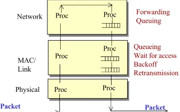
prototype, or product – share some basic architectural features that result in severe under-utilization of the performance potential. First, the operations are hop-centric in that processes are terminated and re-initiated at every hop. Each packet experiences a large amount of processing, queueing and contention at each hop, as shown in Figure 1. Specifically, the packet has to be
processed at three layers for header stripping etc., re-queued at the network and MAC layers, processed again for header insertion,
and re-contend for channel access, with the obligatory backoff and
retransmission. And this happens all over again at the next node,
and at every single node along the way to the destination.
Proc Proc
Proc Proc
Proc
Proc
Queueing Wait for access Backoff Retransmission
Physical MAC/ Link
Network ForwardingQueuing
Packet Packet
Figure 1: Today's ad hoc networking imposes a lot of delay at each relay node, making it a performance bottleneck as data rates increase.
This is like a subway train design that has passengers get off at every intermediate station enroute to their destination, go outside the station, get in line for a fresh ticket, wait all over again for the next train and board it! While the analogy is not completely valid, the point is that there is some obvious and significant redundancy that can be removed2.
This within-node and especially the re-contention delay has a drastic impact on performance, not only on path latency but also on effective capacity. With increasing size, and decreasing range resulting from the need to operate at higher frequencies where more bandwidth is available, path lengths in tens of hops is not inconceivable. This results in high end-to-end latency. At lower data rates, the latency is not an issue, but at higher data rates the
1We use the term MANET to cover any multi-hop wireless network in
which nodes relay packets for each other, including military packet radio networks, sensor networks, and rooftop/mesh networks
2This issue is far more critical for MANETs than for wireline networks
because the medium access time is orders of magnitude more expensive Permission to make digital or hard copies of all or part of this work for
personal or classroom use is granted without fee provided that copies are not made or distributed for profit or commercial advantage and that copies bear this notice and the full citation on the first page. To copy otherwise, or republish, to post on servers or to redistribute to lists, requires prior specific permission and/or a fee.
system becomes “latency-limited” [3]. For example, using equation (3) in [3], at 20 ms per hop latency, 50% utilization, and using 1.5 Megabyte file size, the “critical” bandwidth above which a 50-hop path is latency-limited is about 24 Mbps – a threshold we have just gone above in recent years as chipset rates went from 11 Mbps to 54 Mbps, and will continue to be above.
Second, the physical layer used in a MANET node is ill-suited for multi-hop or relay-based communications. We observe that in spite of all the research and development, we continue to use chipsets and modem designs that were conceived and optimized for single-wireless-hop networks (e.g. W-LANs or cellular networks). The current MANET physical layer is optimized for two primitives – to receive and to transmit, whereas in MANETs the most common operation, and one that is the essence of wireless multi-hop networking, is relaying. Since relaying is not a primitive operation, current designs are forced to construct a chain of receive-store-process-queue-forward-contend-transmit involving several layers. Rather than building complex protocols above a ill-suited physical layer, MANETs require a fresh approach to physical layer design, one designed for MANET operations from the ground up.
Third, current architectures fail to take advantage of the broadcastnature of MANETs, and instead, actually try to curb it by imposing rigid wireline-like thinking. For instance, when a node transmits a packet, it delegates a single neighboring node to retransmit the packet. All other neighboring nodes that receive the packet are made to discard it, representing a colossal waste of energy by the time the packet winds its way to its ultimate destination. Imagine if we could harness that energy to increase the signal quality and hence capacity of the end-to-end path. Whereas the broadcast channel naturally lends itself to such path diversity, most MANET routing protocols provide only single-path routes.
These and other architectural features underlying almost all of the research, thinking and development in ad hoc networks fundamentally limit the performance – chiefly the latency, capacity and robustness. The increasing ubiquity of MANETS in both military and civilian communications infrastructure is likely to create a demand for large MANETs with near-wireline performance. A notional performance requirement, and one that we use as a goal for ourselves is a network with 10,000 or more mobile ad hoc nodes, diameter (and hence path lengths) of 50-100 hops, transport capacity of 1 Gbps, end-to-end latency less than
10 ms, and wireline-like robustness. Such requirements are
applicable to future military networks of sensors, robots, soldiers, ground and airborne vehicles [2]. Further, an architecture that meets this goal will also be applicable to hybrid wired/mobile-wireless civilian networks where the total number of wired/mobile-wireless hops is large. Current MANET architecture has scope for incremental advances, not the order-of-magnitude gains we need to meet such challenging requirements. We need a new generation of MANETs with a radically new architecture.
2. OUR VISION FOR THE WAY
FORWARD
Our vision for the next generation MANET architecture has three key parts: a physical layer that is optimized for multi-hop wireless networking; access to the medium for the entire path; and cooperative transport of packets. We elaborate on each aspect below.
A key part of MANET control is determining which set of nodes relay the packet from the source to the destination (routing), and transporting along this chosen path (forwarding). Currently, both of these are done two layers above the physical layer. We put forth a radical thought – to move both functions (jointly called
relaying) to the physical layer where they are closest to packet
entry and exit. Relaying is thus an integral part of the physical layer – a third primitive on par with transmitting and receiving. Indeed, one should not even need to wait for the entire packet to be received before being re-transmitted. In the ideal case, a bit stream continuously rolls in and rolls out re-energized, without having to store, or re-contend. In other words, both unicast and global broadcast packets are switched at the physical layer itself3,
without the involvement of any of the higher layers. Cognizance of the network, particularly the origin and end-destinations of packets, is present at the physical layer.
As discussed earlier, current MANETs operate in a hop-centric manner, with the fundamental or atomic unit of operation being a hop or a link. In contrast, our vision is of path-centric
operations, in that the atomic unit of operation extends to multiple hops, and in the ideal extreme comprises the entire path. That is, end-to-end transport does not involve the termination and subsequent re-initiationof the access protocol procedures at every intermediate hop. In particular, medium access control is
path-oriented in that access to the channel at the source is for multiple
hops enroute to the destination and the packet does not have to re-contend at each intermediate hop.
A key part of our vision is the cooperative transport of packets. The idea behind cooperative transport is to opportunistically harness unused resources to increase the capacity of a path. The emerging concept of cooperative diversity
([4][5][6]) is a powerful method for doing this at the physical layer. In cooperative diversity, nodes simultaneously retransmit the same packet to be diversity-combined at receivers. The next generation MANET architecture should embrace and extend this concept, making it an integral part of MANET thinking and design. In essence, our vision is that a “band” of nodes between the source and the destination cooperatively guide an energy
conduit by re-energizing and combining to create a high-capacity,
highly robust pipe.
Executing the above vision would require a re-design of the transceiver, in particular making specialized chipsets for MANET nodes distinct from chipsets for single-hop communications. Such specialized chipsets would be optimized for MANET operations by including relaying as a first class citizen at the physical layer, and accommodating distributed waveform control for diversity. Just as specialized graphics chipsets revolutionized the graphics industry in terms of performance, we believe that MANET-specialized transceiver architecture and chipsets will significantly improve the performance of MANETs.
In what way will this new vision improve the performance? We believe that performance improvements will be significant at least in latency, capacity, path reliability, and energy. The dramatically reduced processing and elimination of re-contending at every hop will significantly reduce latency. Capacity will be
3This idea of switching “on-the-fly” is reminiscent of “cut-through” or
significantly increased by virtue of cooperative transport. It will also increase as a result of switching at the physical layer by eliminating the delay bottleneck, allowing path capacity to better approximate link capacity. Path diversity is a natural outcome of our architecture and, along with the use of cooperative transport significantly increases path robustness. Finally, energy consumption will be reduced due to the reduced processing and contention, and the use of cooperative diversity.
Most importantly, it will remove the architectural bottleneck that prevents the translation of ever-improving transceiver bit rates to network-wide or end-to-end performance. Elevating the performance profile of mobile networks to the same plane as wireline networks will enable MANETs to become part of the Internet infrastructure rather than being at the edge of it. This will help support a whole class of high-bandwidth, low-latency applications – including audio/video conferencing, real-time imagery and remote control, and telemedicine – to mobile/remote users with the same quality of service as users on the Internet.
Can this vision be achieved, and if so how? In the next section, we present a design concept that shows that the vision, while challenging, is not out of reach. It is one example of instantiating the general ideas outlined earlier, and by no means the only one. We emphasize that these are not full-fledged designs at this stage, only solution approaches that look promising. Challenges remain in developing these completely. Some of these are discussed in section 4.
3. A DESIGN CONCEPT
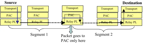
We begin with a quick overview of our architecture. The functional layering and control flow is illustrated in Figure 2. Our notional stack consists of three layers – a relay-oriented
physical layer (Relay PL), on top of which there is a path access
control (PAC), on top of which we directly have the transport
layer (session and application layers not shown for brevity). There is no network or routing layer – this functionality is captured at the (relay-oriented) physical layer. Paths are composed of
segments, forwarding is at the physical layer within a segment and
medium access is over an entire segment. We elaborate below. The relay-oriented physical layer not only receives and transmits packets but is also capable of automatically relaying, without having the packet leave the physical layer. The key idea is
to couple the receive chain of operations (acquisition,
demodulation, decoding, etc.) to the transmit chain of operations (coding, modulation, spreading etc.) and control the coupling so that the node can selectively relay the packets, as close to real-time as possible. Full duplex operation is provided using multiple frequencies. A transit control table at the physical layer uses information within and/or about the packet to decide whether or not a node should relay an incoming packet. The transit control table is populated by adapting a proactive routing protocol to run at the physical layer. We elaborate further in section 3.1.
Our concept of Path Access Control (PAC) is a multi-hop
floor acquisition mechanism that secures access for physical layer relaying over as many hops as possible toward the destination, ideally all the way to the destination. The basic idea is to extend conventional contention-based floor acquisition (using RTS-CTS) to be path-oriented. That is, floor acquisition control messages travel multiple hops along the path, switched at the physical layer, Specifically, and as shown in Figure 2, PAC acquires the floor in units of variable-length segments. Multiple concatenated segments
constitute a path. As depicted in the figure, a packet never exits
the physical layer throughout a segment. Thus, the PAC is only
invoked between segments, ideally only at the source. Packet error control only happens between segment endpoints, or one may let the transport layer take care of it. The segment length is determined by the particular PAC mechanism, for which we discuss a possible design in section 3.2.
Transport
Relay PL PAC
Transport
Relay PL PAC
Transport
Relay PL PAC
Transport
Relay PL PAC
6RXUFH 'HVWLQDWLRQ
Transport
Relay PL PAC
6HJPHQW 3DFNHWJRHVWR 6HJPHQW 3$&RQO\KHUH
Figure 2: Layering and packet flow in the proposed architecture
Multiple nodes receiving a packet may cooperatively relay it, to be diversity-combined at receivers. The relaying delay, power, and other parameters are controlled at the Relay PL. Packets move toward the destination(s) in stages rather than hops, with diversity combining at each stage. The choice of nodes to relay is done using distributed network flow and disjoint-path techniques. For synchronization and combining at a receiver, recent work ([4][5][6]) can be leveraged.
The three key elements of the architecture – relay-oriented physical layer, path access control, and cooperative transport are inter-related and synergistically combine to yield benefits in excess of their individual value. Path access control is much faster because its control packets are relayed at the physical layer, and at the same time, physical layer switching is possible only because the channel is reserved up front by path access control. Similarly, cooperative diversity is enabled by having relaying at the physical layer, and at the same time, routing control packets use cooperative diversity for fault tolerance. The architecture preserves many key features of MANETs, including node mobility, distributed operation, etc.
3.1 Relay-oriented Physical Layer
Our high-level strawman design for a relay-oriented physical layer is based on a multi-frequency/multi-band system, with the transmitter and receiver tunable to different, non-interfering frequencies. Thus, full-duplex operation, that is, simultaneously transmitting and receiving using multiple frequencies4, is possible.
Using this, our design concept is to pipeline the transmit and receive operations, so that the first parts of the packet are transmitted while the other parts are being received. For instance, while block Bi is being decoded, a (previous) block Bi-1 might be
encoded for relayed transmission and a (next) block Bi+1 might be
demodulated.
Relaying consists of two problems: routing, that is, deciding which node(s) do the relaying, and forwarding, that is, the actions each node should perform to actually make the packet go along the chosen path. The problem, essentially, is to decide, for a packet originating at S and destined for D, whether to keep the packet (when X=D), discard it, or re-broadcast (relay) it. We first
4 Alternatively, one could use multiple orthogonal codes instead of
consider forwarding. That is, for the moment, assume that the decision of whether to keep, discard or relay is available, and consider how to implement that decision within the physical layer. Following this, we shall address how to make this routing decision.
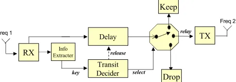
Our design is as follows. We (a) extract certain information from the front of the packet (e.g. the destination), or of the packet (say received signal strength); (b) use this information to decide whether to keep, discard, or relay the packet, and do this while the other parts of the packet are being received; (c) shunt the incoming bit stream to the transmit chain. In other words, we look at the packet header and “throw” a switch to one or more of three positions – relay, drop, or keep. This design concept is illustrated in Figure 3, and explained below.
A packet is received by the Receiver (RX) module on frequency F1. The physical layer header block is sufficient to make the decision of keep/drop/relay, and as soon as this is available, the information for this is extracted and a “key” is sent to a Transit Decider module. This module implements a lookup function from the key to one of keep/drop/relay and sends a select
signal to a switch selecting the right position for the packet. The incoming bit stream is delayed for just enough time for the switch to be set, upon which the transit decider sends a release signal de-activating the delay. The incoming blocks are then sent to the Transmitter (TX) module to be transmitted on frequency F2.
We note that the TX (RX) module may contain any chain of (De)modulation, (De)scrambling, (De)coding, (De)spreading functions, depending upon the receiver design. The above shows a design where the information extraction is done after the last function in the chain (say decoding), but that does not necessarily have to be the case. For instance, it may be possible to identify information for the transit decider after just demodulating the packet and so one could simply re-modulate the packet and relay it. In the extreme, only the header might be demodulated or decoded and, if the decision is to relay, the rest of the waveform simply sent to a power amplifier. These choices represent a variety of designs from “decode-and-forward” to “amplify-and-forward”. Note however that the amplify-and-forward approach decreases the SNR at every hop due to noise amplification and may not be general solution for a large number of hops.
What kind of latency performance can we get using this approach? To get an idea, we did a back-of-the-envelope calculation, as follows. The total per hop latency includes the propagation delay, the receive processing, the transmit processing and the transit decision time (amount of Delay above). Assuming IP Ping packets, decode-and-forward, 3 usec propagation delay per hop, 50 Mbps data rate, frequency switching time of 5 usec (based on our PAC design – see section 3.2), and transit decision time of 5 usec, the average latency per hop for our notional design comes to about 68 usec5. For a 50-100 hop path, we get round-trip
ping latencies of 10–20 ms, which is far better than current norms and compares favorably with typical ping delays on the Internet.
We now turn our attention to the question: how is the transit
control table populated, which is essentially the question of
deciding the sequence of nodes (route) that will relay the packet.
5Some pessimistic assumptions are made to offset the fact that there may
be things we have not thought about. E.g. 10 usec “miscellaneous time”, and a worst-case block size of entire packet. Details omitted due to space constraints.
A number of MANET routing mechanisms have been developed for this purpose over the past several years. We use a proactive
link-state routing approach as part of this design concept.
The proposed routing mechanism adapts link-state routing to run at the physical layer, that is, the routing updates and neighbor discovery probes, if any, do not use the MAC layer. Link State Updates (LSUs) are generated in a conventional manner when a link goes up or down. The flooding of a generated LSU is based on ideas in [5] and a novel idea for “capturing” nodes [C. Santivanez, personal communication]. It consists of a network
preamble followed by the actual LSU, both of which are sent
relayed (re-broadcast) at the physical layer, using cooperative diversity techniques. The network preamble is a multihop preamble that is large enough that it outlasts most ongoing packet transfers and “captures” all nodes in the network – that is, it gets them to ignore data transmission or reception and tune into the ensuing LSU. The preamble and the LSU are relayed at the physical layer – the RX coherently combines multiple updates using diversity of transmission from various nodes. A bit in the header indicates that this is a “flood” packet. The transit decider (see Figure 3) then sets the switch to “relay” and “keep” if it has not seen this packet before. Otherwise it is set to “drop”.
TX
RX
Delay
Transit Decider
Keep
key Info
Extracter release
select
Drop relay
Freq 1
Freq 2
Figure 3: Notional block diagram of a relay-oriented transceiver.
Flooding cooperatively in this manner has a number of advantages. First, capturing the nodes ensures that the LSUs are not missed as a result of a node being busy transmitting or receiving (a common cause of flooding unreliability in current systems which unreliably broadcast LSUs). This, along with the cooperative combining utilizes the collective transmission powers to make the dissemination far more robust [5]. Second, the dissemination delay is dramatically reduced as the updates do not have to wait to access the channel at every hop. This results in quicker convergence of the routing protocol, and therefore better responsiveness to node mobility. We observe that as data rates increase, it is not how many control messages are sent that is important, but how reliably it propagates and how long it takes for these to propagate6.
Conventional proactive routing protocols typically generate “next hop” routing tables which are different from the transit table discussed earlier. However, it turns out that, at least for shortest hop routing, one can just as easily generate a keep/relay/drop table for a source-destination pair, given the topology. In particular, a destination-rooted sink tree may be used to determine whether or
6For a given network size, density and mobility, the fraction of capacity
not relay a packet. The transit table at a node X contains mappings from every source (S), destination (D) pair to one of keep/relay/drop as follows: if the D = X, then keep, else, if X is on the branch from S to D in the sink tree, then relay, else drop.
Routing at the physical layer does not necessarily mean that routing logic such as topology databases and the Dijkstra algorithm have to be implemented in ASIC. The code (perhaps the same existing open source implementations) can be placed in a Flash ROM (which are increasing in size and decreasing in cost by the day), and connected to the rest of Figure 3 which might be implemented using FPGAs.
Hardware components and capabilities for constructing a relay-oriented physical layer are well within the state of the art in chip design – it is only a question of putting them together in the right manner. In fact, hardware is not the only choice. The recent arrival of software radios into the commercial marketplace [7] even into the open source world [8] makes it an additional avenue for the realization of our vision. In software radios, much of the RX and TX box is in software. The entire switching functionality can be developed in software with the “delay” box being a shared buffer between the transmit and receive chains. No new hardware needs to be manufactured. Indeed, with increasing presence of software radios both in the military [9] and commercial [7] arenas, the time is ripe for a software-defined relay-oriented radio. We note, however, that processing and other delays are higher with software radios, but that is bound to reduce as more investment is made into refining the technology.
One obvious problem with such “cut-through” relaying whether in wireless or wireline, is that we cannot always be sure that the channel is available for re-transmission to the next hop. This is the subject of the next subsection.
3.2 Path Access Control
As briefly discussed earlier, Path Access Control (PAC) is a mechanism that acquires the floor for multiple hops, namely a
segment, within which packets are relayed at the physical layer.
The entire source-destination path is comprised of multiple segments (ideally 1, worst case h, the number of hops).
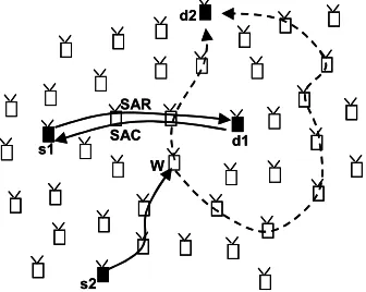
A design concept for PAC is illustrated using an example in Figure 4, and briefly explained below. This scheme is a natural extension of the 802.11 DCF MAC protocol [10] to a path-centric regime.
Consider the source s1 that wants to transfer a burst of data (one or more packets) to a destination d1 as shown in the figure. The PAC in s1 sends a Segment Access Request (SAR) which gets relayed at the physical layer until it encounters an ongoing transfer. For this s1-d1 transfer, assume that the SAR makes it all the way to d1, without encountering an ongoing transfer and without exiting the physical layer. The PAC in d1 replies with a
Segment Access Clear (SAC), which again is relayed through the
physical layer and reaches s1. The SAR can be thought of as a “multi-hop RTS” and the SAC as a “multi-hop CTS”, switched at the physical layer as discussed in section 3.1.
Upon receiving the SAC, a data burst (one or more packets) is relayed as discussed in section 3.1. An acknowledgement may be sent, or we may simply let the transport layer take care of reliable delivery.
Floor acquisition is performed along the path by having the nodes that overhear the SAR or SAC create state to protect the transfer. We call such nodes, illustrated by checkered
(grey-shaded) nodes in the figure as the sentinels for the transfer. The sentinel state is the path-centric equivalent of the Network Allocation Vector (NAV) in the 802.11 DCF in that it protects the current access from other contenders. Consider now source s2
wishing to send to destination d2, while the s1-d1 transfer is in progress. The SAR from s1 hits a sentinel (W) and is prevented from going further. Instead the SAR is delivered to the PAC at this intermediate node W, terminating a segment. A return SAC clears the way for data burst transfer over this segment. Now, node W
can use another route to set up the next segment going “around” the sentinels (shown using a dashed arrow from W to d2). Or it can wait until the s1-d1 transfer completes, and use a more direct path (shown by another dashed line from W to d2).
d2
s2
d1 s1
SAR
SAC
W d2
s2
d1 s1
SAR
SAC
W
Figure 4: PAC example. The s1-d1 path is activated first and consists of a single segment. The s2-d2 path consists of two segments, demarcated at "sentinel" W. Dashed lines show two possibilities for second segment.
Packets may be transmitted without a preceding SAR/SAC, just like the DATA-ACK mode in 802.11 DCF does not use RTS/CTS. In such a case, each packet behaves as the SAR does.
One important issue is the setting up of the frequencies of each node’s RX and TX to enable full-duplex operation. Specifically, each node needs to use different RX and TX frequencies and the TX frequency of a node should match the RX frequency of the next node along the path. There are two approaches to this: select a TX frequency along with the transit decision and let the RX “auto-tune”, i.e., sense on all frequencies and tune to the one on which energy is the most. Wideband sensing and spectrum agility technologies are fast emerging ([13],[7]) and so the above is not unreasonable. A simpler, less efficient approach is to always use SAR/SAC and transfer them on an apriori assigned frequency in half-duplex mode, and set the RX and TX frequencies appropriately as they go for the ensuing burst. In either case, it is easy to see that frequencies can be reused along a long path. Specifically, any path can be full-duplexed thus using no more than 3 frequencies, and perhaps 2 if appropriate code division multiplexing is used.
propagation, 3.2 us receive, 5 us relay processing, 3.2 us retransmit). Taking the average segment length as about 10 hops, a packet has to wait about 15x10x2 = 300 us to acquire a segment. With 100 Mbps, even 30 hops takes only about 600 us, which is comparable to a single hop floor acquisition in current 802.11 W-LANs where the time to acquire the channel is of the order of 650 usec (RTS-CTS roundtrip, ignoring processing time). In other words, by virtue of physical layer relaying, elimination of headers, and dramatically reduced processing we can acquire a few tens of hops in about the same time than it takes to acquire a single hop today.
The proposed PAC scheme supports mobility of nodes, to about the same degree as conventional 802.11 networks. This is because the timescale of SAR/SAC and corresponding sentinels is much smaller than the timescale within which mobility happens. As noted earlier, the SAR/SAC is like multi-hop RTS/CTS. Just as mobility is typically not a problem within an RTS/CTS/DATA/ACK due to the relative timescales, it will not be with the proposed scheme.
One interesting question is: how long should a segment be?
One solution is to let it be as long as it can, that is, the SAR keeps going till it hits a sentinel. One downside of this is that if the segment is very long, and the channel error prone, we may not be able to regenerate the packet at the end of the segment. This tradeoff, especially if we throw in forward-error-correction as an additional dimension, is an interesting research problem.
The segment concept generalizes a “link”. Near-zero-latency physical layer relaying makes the segment no more “expensive” than a link. In fact, one can think of a segment as a long link re-energized in between. So now we have the equivalent of a network where “links” are much longer (without increased transmit power), and in fact can curve around obstacles! This results in better spatial reuse and hence higher capacity.
Path-centric access hinges on being able to find long enough segments. We believe that this will be the case because each burst lasts only a very short amount of time by virtue of physical layer switching (refer latency arguments earlier), and therefore the number of bursts active at any given moment will likely be quite small. Thus, we are very likely to find one- or two-segment paths (going around and between sentinels) for the majority of the sessions in all but very heavily loaded networks, in which case it will be no worse than hop-centric access (segment length of 1).
3.3 Cooperative Transport
We have until now implicitly considered packet transport along a single path. Routing along a single path, as is mostly done currently, fails to exploit the richness of the topology and the additional resources (e.g. power) of other nodes that could potentially help in the packet transport. MANETs offer the “wireless broadcast advantage” – a single transmission reaches many nodes [11], and “wireless cooperative advantage” – multiple nodes can cooperatively transmit the same packet that could be exploited on an end-to-end basis [6]. What if we could harness nodes that are not otherwise busy to help transport packets on a pathP? And have nodes in P return the favor when they are not busy?
This idea forms the basis of cooperative transport, which is an integral part of our architecture. Cooperative transport of packets can be done at the network layer – this is the conventional
multipath routing, or load balancing, in which packets are
multiplexed over disjoint parallel paths. This however has a number of problems in MANETs [12]. A more powerful way of cooperative transport is the use of cooperative diversity, which operates entirely at the physical layer.
Cooperative diversity is the near-simultaneous transmission of the same information by multiple nodes that is coherently combined at the receiver. Another way of thinking about it is as an antenna array where the nodes are antenna elements. The use of cooperative diversity results in much better SNR at the receiver (essentially the power of many nodes can be made to add up).
Information-theoretic and engineering aspects of cooperative diversity have been investigated by several researchers ([4],[5],[6],[19]). We seek to extend those ideas to build high capacity energy conduits across a large ad hoc network, and extend the relay-oriented physical layer design presented in section 3.1 to accommodate this.
We envision the energy conduits to be built using cascaded transmissions [19], as illustrated in Figure 5 and explained below. In the illustration, nodes S and D are the source and end-destination respectively. Node S broadcasts a packet that is re-broadcast near-simultaneously to make forward progress toward
D. Nodes that do not contribute to forward progress (nodes that are not filled in the figure) discard the packet. Nodes that do contribute to forward progress (checkered nodes in the figure) receive the re-broadcasts and diversity-combine to decode-and-forward the packet and the next set of nodes repeat this .
S
D
Figure 5: Cooperative diversity adapted to large ad hoc networks. A 3 "stage" path is shown.
The level of synchronization required for decoding depends upon the receiver technology in place. Use of MIMO-like [14] receivers alleviate the synchronization requirements so that nodes can retransmit without symbol-level synchronization. Still, the more close-apart the transmissions are, the better in practical terms.
The increased SNR at each stage is “transferred over” to the next stage. At each stage, the increased SNR can be used to select higher-level modulation schemes to increase capacity, or lower the transmit power to save energy. In essence, we have increased the data rate per energy unit from S to D by harnessing other nodes and using simultaneous transmissions to our benefit rather than detriment.
A key part of cooperative transport is how to select nodes for relaying, how to assign transmit power and other waveform characteristics to each selected node in a distributed fashion, and how to control the delays so that coherent combining is possible. Maximally disjoint path and/or network flow algorithms may be a good starting point here.
Instead of just one node relaying, multiple nodes may relay, and the “delay” block (see Figure 3) is adjusted to adequately synchronize the transmissions. The RX module now contains the MIMO or equivalent technology required to diversity-combine the simultaneous transmissions.
4. RESEARCH CHALLENGES
We presented a sample set of ideas in the previous section as a high-level concept validation exercise. Much work remains to take it from a promising concept to a full-fledged design. Also, what we described constitutes just one way of realizing our vision. Better alternatives may well be possible and should be explored.
There are a number of exciting research topics within the overall approach. Some possibilities and new directions were given as the design concept was being presented. Here are some more (as much as space constraints will permit).
• A hardware (transceiver chipset) design that completes the outline given in Figure 3. More generally, the problem is to create a low-cost MANET-specific transceiver that is built for relaying from the ground up.
• Generalizing the decode-and-forward design to amplify-and-forward and other intermediate stages, and developing hybrid schemes. For instance, a node might perform amplify-and-forward for a few hops until the noise accumulation becomes too much, then decode, and repeat amplify-and-forward for the next few hops.
• Developing contention-based schemes for path access control. One may think this problem through afresh or develop further the approach outlined in section 3.2.
• Developing contention-free path access control, or a path centric TDMA protocol. The challenge here is to extend the notion of a slot to be path-centric – i.e. allow multiple-hops within a single slot, which requires global control coordination.
• Determining optimal segment lengths. This includes considering error characteristics, other flows etc. Segment arrangement might be modeled using graph-theoretic techniques, say, as 2-D bin packing.
• Enabling the “crossing” of segments instead of terminating them at sentinels. This might, for instance, be done using orthogonal coding techniques or opportunistically using gaps between packets.
• Integrating and jointly optimizing routing and cooperative transport. This involves selecting the optimal set of nodes in each stage that will cooperatively transmit so that path capacity is maximized, energy is minimized.
• Integrating the above with path-centric access, for instance a path access control mechanism that obtains access for the entire energy conduit. Extending the relay-oriented physical layer to accommodate this joint scheme.
Clearly, there is no dearth of interesting problems. And in addition, the usual problems of security, differentiated quality-of-service, energy conservation and TCP-sensitivity need to be reconsidered in this new regime. Finally, the architecture blurs the boundary between signal processing and networking and will need
to bring together Electrical Engineering and Computer Science in an unprecedented manner. Perhaps getting these “EE folks” and “CS folks” to work together is the greatest challenge of all!
5. RELATED WORK
The idea of switching at the physical layer immediately reminds one of “cut-through” or “wormhole” routing techniques in wireline optical networks [15],[16]. In cut-through routing, packets entering a network node on one interface are forwarded, without storing, on another interface. Although the basic idea is similar, the problem is vastly different in ad hoc networks, chiefly due to the broadcast nature of communications and the resultant need for access control. Further, transmission and reception require a number of steps in waveform processing, and node mobility requires dynamic switching (transit table).
In the context of mobile ad hoc wireless networks, there exists work on “label switching” at the medium access or link layer [17] which pushes the forwarding function one layer down. In [18], access time is reduced by having the ACK for a packet double up as an RTS for the next hop. Our architecture involves a more fundamental change compared to these works – switching is done not at the MAC but the physical layer, and floor acquisition is done for multiple hops at a time. Unlike the other works, our architecture allows sending a part of the packet while receiving another part – this is key in bringing down the latency.
Recently there has been considerable interest in and investigation into cooperative diversity in ad hoc networks ([4],[5],[6],[19]). While these investigate the information-theoretic aspects of numerous variants of the general idea, we still need to develop and integrate them with routing and path access control to create end-to-end energy conduits.
Overhead reduction in routing protocols using novel techniques has been a subject of much research. For instance [22] proposes a gossiping-based approach where a node forwards a message with some probability. Our proposal is different in that it is a flooding-based approach, but at the physical layer and with better robustness and lower delay.
Finally, the question of theoretical limits on transport capacity achievable by such cooperative techniques has been studied in [20],[21]. It has been shown that there is a dichotomy between the cases of relatively high and low attenuation (with a crossover at exponent of 3). When attenuation is above this, transport capacity is bounded by a constant multiple of the sum of node powers and non-cooperative transport is order-optimal. However, there is still a huge gap for real systems to reach the theoretical bounds. Further these works do not consider latency which needs to be minimized.
6. CONCLUDING REMARKS
We envision a new generation of ad hoc networks whose performance plane is on par with wireline networks in terms of latency, capacity and robustness. Such a capability would enable an emerging breed of high-bandwidth real-time multimedia applications to run over large ad hoc networks. Exciting new possibilities such as telemedicine to the edge of a remote disaster area or battlefield would suddenly be within reach and save lives.
per-hop delay, prevents technological advances such as new modulation schemes, beamforming, MIMO etc. from translating into bottom-line, end-to-end performance
The next generation of MANETs needs to un-shackle itself from the wireline-inherited legacy thinking. We need an architecture that is MANET-specialized from the ground up. We need to think beyond “cross-layer” and question fundamental assumptions about what function belongs in what layer. Sharing a broadcast channel in a multi-hop context is a unique problem that requires a departure from layering norms established for wireline or single-hop wireless networks. The essence of ad hoc networking is relaying and the architecture should reflect that and optimize for it from the physical layer up.
We presented a design concept based on a relay-oriented physical layer which encapsulates both the routing and forwarding functions, a path-centric floor acquisition control (path access control), and cooperative transport. Much work remains to be done, however, in working these ideas out and analyzing their performance theoretically and experimentally. Further, our design concept only covers a small part of the multi-dimensional research space opened up by the radical departure from convention.
It is our hope that this paper convinces the community on the need to question fundamental assumptions about current MANET architecture, and inspires novel ideas for building the next generation of mobile ad hoc networks.
7. ACKNOWLEDGEMENTS
We thank our BBN colleagues, notably C. Santivanez, C. Partridge, V. Kawadia, C. Elliott and J. Redi for their valuable feedback. We also thank the Mobicom TPC for their suggestions, which helped greatly to improve the paper.
8. REFERENCES
[1] T.L. Huston, J.L. Huston, “Is telemedicine a practical reality”
Communications of the ACM, Vol 43, No.6, 2000 (also see
http://www.ngi.gov/apps/nih/rad.html)
[2] Future Combat Systems http://www.boeing.com/defense-space/ic/fcs/bia/about.html
[3] L. Kleinrock, “The Latency/Bandwidth Tradeoff in Gigabit Networks,” IEEE Communications Magazine, April 1992 [4] J.N. Laneman, D.N.C. Tse, G.W. Wornell, “Cooperative Diversity in Wireless Networks: Efficient Protocols and Outage Behavior”, IEEE Transactions on Information
Theory, vol. 50, no. 12, pp. 3062-3080, Dec. 2004.
[5] A. Scaglione, Y-W. Hong, “Opportunistic Large Arrays: Cooperative Transmission in Wireless Multihop Ad Hoc Networks to Reach Far Distances,” IEEE Transactions on Signal Processing, VOL. 51, NO. 8, August 2003.
[6] A. Khandani, J. Abounadi, E. Modiano, L. Zhang, “Cooperative Routing in Wireless Networks,” Allerton
Conference on Communications, Control and Computing,
October, 2003.
[7] Vanu Inc. http://www.vanu.com
[8] Gnu Software Radio http://www.gnu.org/software/gnuradio [9] Joint Tactical Radio System (JTRS) http://jtrs.army.mil [10] M.S. Gast, “802.11 Wireless Networks: The Definitive
Guide'', O'Reilly and Associates, April 2002.
[11] J.E. Wieselthier, G.D. Nguyen, A. Ephremedis, “Algorithms for energy-efficient multicasting in ad hoc networks,” IEEE MILCOM 1999, pp. 1414-1418.
[12] M.R. Pearlman, Z.J. Haas, P. Sholander, S.S. Tabrizi, “On the impact of alternate path routing for load balancing in mobile ad hoc networks,” ACM Mobihoc 2000, Boston, Massachusetts.
[13] D.C. Bannister, C.A. Zelley, A.R. Barnes “A 2-18 GHz wideband high dynamic range receiver MMIC,” IEEE Radio
Frequency Integrated Circuits (RFIC) Symposium, 2002
[14] Gesbert et al “From Theory to Practice: An Overview of MIMO Space-Time Coded Wireless Systems” IEEE Journal
on Selected Areas in Communication, vol. 21, No 3, April
2003, pp. 281-302.
[15] P. Kermani and L. Kleinrock. Virtual Cut-through: A New
Computer Communication Switching Technique. Computer
Networks, 3(3):267--286, September 1979.
[16] E. Leonardi, F. Neri, M. Gerla, P. Palnati, “Congestion Control in Asynchronous High-Speed Wormhole Routing Networks”, IEEE Communication Magazine, Nov. 1996. [17] A. Acharya, A. Misra, and S. Bansal, “A Label-switching Packet Forwarding Architecture for Multi-hop Wireless LANs,” IBM, Tech. Rep., 2002.
[18] D. Raguin, M. Kubisch, H. Karl, A. Wolisz, “Queue-driven Cut-through Medium Access in Wireless Ad Hoc Networks”,
In Proc.IEEE Wireless Communications and Networking
Conference (WCNC),, Atlanta, Georgia, USA, March 2000.
[19] M.A. Tope, “Performance Evaluation of a Cooperative Diversity Enhanced Ad Hoc Network,” Master’s Thesis, Naval Postgraduate School, Monterrey, California. [20] P. Gupta, P.R. Kumar, “Towards an Information Theory of
Large Networks: An Achievable Rate Region,” IEEE
Transactions on Information Theory, vol. 49, no. 8, pp.
1877-1894, August 2003
[21] L-L. Xie, P.R. Kumar, “A Network Information Theory for Wireless Communication: Scaling Laws and Optimal Operation,” IEEE Transactions on Information Theory, vol. 50, No. 5, pp. 748-767, May 2004.
[22] L.Li, J. Halpern, Z. Haas, “Gossip-based ad hoc routing”, in
Proc. IEEE INFOCOM 2002