Structure optimization of cam executive component and analysis of
precisely applying deep-fertilization liquid fertilizer
Wenqi Zhou
,
Jinwu Wang
*,
Han Tang
(College of Engineering, Northeast Agricultural University, Harbin 150030, China)
Abstract: Since there are some problems in the previous cam of deep-fertilization liquid fertilizer applicator, such as poor precision and low-fertilization performance, a method of the contour line of a cam was proposed based on Matlab GUI development platform. Bernoulli’ equation between the liquid fertilizer and the pressure valve of the fertilizer-spraying needle was founded. Moreover, the motion angles of a rise travel and return travel were corrected and the corresponding parameters of the contour line of the cam were obtained. Equations of cam moving from rise travel to return travel were derived according to the simple harmonic motion. In addition, 3D model of cam was established by applying the Pro/E software and the rationality of the cam design was verified. The static analysis of the cam was carried out under working conditions and the corresponding dynamics analysis was performed based on D’Alembert’s principle. And then relationships between the binding force and the drag torque were obtained. A bench test indicates that when the pressure of a hydraulic pump is 0.5 MPa and the velocity of a output shaft is 50 r/min, the average consumption of the fertilizer is 19.7 mL for each measurement, which meets the corresponding agronomic requirement, i.e. 20 mL. When the rotation angle of the cam is 8.6° and the rise displacement of a plunger is 0.84 mm, the mouth of the fertilizer-spraying needle sprayed liquid fertilizer as soon as it got into the soil and stopped spraying as soon as it got out of the soil. The results show that the designed contour line of the cam meets the requirement, that is, the mouth of the fertilizer-spraying needle should spray liquid fertilizer as soon as it gets into the soil and stop spraying as soon as it gets out of the soil, which meets the agronomic requirements, that is, fertilizer should be sprayed deeply and precisely. And this study lays a theoretical foundation for designing the cam of intermittent type distributor and provides relevant parameters.
Keywords: liquid fertilizer applicator, cam, precision and deep fertilization, Bernoulli’ equation, D’Alembert’s principle, Matlab, test, optimization
DOI: 10.25165/j.ijabe.20191204.4865
Citation: Zhou W Q, Wang J W, Tang H. Structure optimization of cam executive component and analysis of precisely applying deep-fertilization liquid fertilizer. Int J Agric & Biol Eng, 2019; 12(4): 104–109.
1 Introduction
The technologies for deep-fertilization liquid fertilizer can improve the crop yield, reduce the pollution and increase the utilization of liquid fertilizer since the liquid fertilizer evaporates to the atmosphere[1-3]. According to the overseas reports, the deep-fertilization liquid fertilizer applicator mainly employed crankshaft to drive fertilizer-spraying needle and device of liquid fertilizer jet for high pressure to impact soil fertilization[4-6], however the fertilization efficiency is low. The deep-fertilization liquid fertilizer applicator designed in China can spray fertilizer into deep soil by the fertilizer-spraying needle, which is high efficiency[7,8].
The intermittent type distributor is a key component of the deep-fertilization liquid fertilizer applicator to spray liquid fertilizer intermittently. The cam is a core component that can effectively make the fertilizer-spraying needle sprays fertilizer precisely in the distributor. Therefore, the effective design of contour curve of the
Received date: 2018-12-10 Accepted date: 2019-05-10
Biographies: Wenqi Zhou, PhD, Lecturer, research interests: design of agricultural mechanization equipment, Email: [email protected];
Han Tang, PhD, Lecturer, research interests: design of agricultural mechanization equipment, Email: [email protected].
*Corresponding author: Jinwu Wang, Professor, research interests: farm machine and mechanical reliability. College of Engineering, Northeast Agricultural University, Harbin 150030, China. Tel: +86-451-55191188, Email: [email protected].
cam has direct influence on the starting time and ending time of spraying fertilizer. If the starting/ending time is too long, a pricking hole mechanism which matches the distributor will spray fertilizer on the soil surface due to earlier spraying time, which wastes the fertilizer and pollutes the environment. On the contrary, longer starting time or ending time will make the insufficient fertilizing amount, therefore less fertilizers will be absorbed by the crops and the production will be correspondingly reduced[9-11].
and the application performance test were carried out so as to verify the correctness and rationality of the cam design.
2 Materials and methods
2.1 Operating principle
The intermittent type distributor consists of distributor-fixing plate, distribution valve, cam, camshaft, valve core and the other parts as shown in Figure 1.
The driving force drives the camshaft, and at the same time, the cam attached to the camshaft does the rotational motion around the axis line of the camshaft and the valve core in contact with the cam does the up-and-down alternate motion during the operational process. The valve core is opened when the cam is in the stages of the rise travel, far repose and return travel. It is closed when the cam is in the stage of the near repose. The liquid fertilizer with a certain pressure from the hydraulic pump is provided for the fertilizer-spraying needle through the distribution valve, which allows the fertilizer-spraying needle to spray liquid fertilizer as soon as it gets into the soil, and to stop spraying as soon as it gets out of the soil. And the displacement of the valve core is a non-linear variation from zero under the action of the cam. Meanwhile, the flow of liquid fertilizer is also a non-linear variation from zero. The energy of the distribution valve in the fertilizer system can’t be balanced by liquid fertilizer energy when the fertilization operation starts, which delays spraying fertilizer when the needle gets into the soil, and stops spraying fertilizer ahead of the time when the needle gets out of the soil.
Therefore, the reasonable design of the cam directly affects the stability of the distributor and the working coordination between the intermittent type distributor and the pricking hole mechanism.
1. Distribution valve 2. Valve core 3. Distributor fixing plate 4. Liquid fertilizer 5. Roller 6. Cam 7. Camshaft 8. Fertilizer-spraying needle
Figure 1 Intermittent type distributor of liquid fertilizer
2.2 Analysis of delayed spray
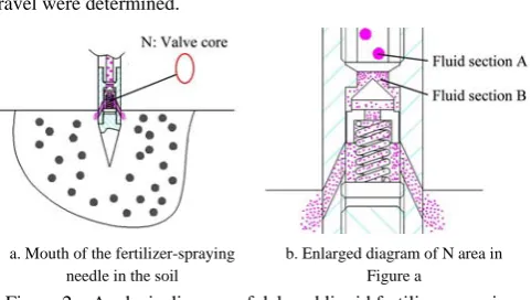
The fertilizer-spraying needle starts to spray fertilizer as soon as it gets into the soil, which is the pre-guarantee for the configuration of cam contour line and it can achieve the precise fertilization. As the pressure valve inside the needle possesses some elastic energy, the liquid fertilizer can offset the elastic energy of the pressure valve when the valve core of distributor moves up by a certain displacement. So, when the fertilizer-spraying needle just gets into the soil, the liquid fertilizer has not been sprayed yet, which leads to a delay in spraying operation. This paper carried out the theoretical analysis, and the mathematical model of liquid fertilizer energy about between the fluid section A and B was established as shown in Figure 2. Eventually, the specific volume of the valve core displacement which could offset the elastic potential energy of the pressure valve was obtained. Moreover, motion angles of a rise travel and return
travel were determined.
a. Mouth of the fertilizer-spraying needle in the soil
b. Enlarged diagram of N area in Figure a
Figure 2 Analysis diagram of delayed liquid fertilizer spraying According to the Bernoulli’s law of conservation of energy, the liquid fertilizer energy equation of between the fluid section A and B was established:
2
2 1
2 w 2
p av
z h kx
ρg g
+ + = + (1)
Because the distance from the distributor to the pressure valve is short, the head loss is small and there are insignificant differences in the position, the gravitational potential energy and energy loss of liquid fertilizer were ignored:
2 2 1
2 2
p v kx
ρg+ g= (2)
where, v Q S
=
2 2 2
1
2 2
p Q kx
ρg+ gS = (3)
where, 0
[1 cos( )]
2
δ
H π δ
h= − , δ0=δ+47°, S=2πrh, h is the cosine
function with the cam angle. When the cam angle is 0, the value of h is 0, which indicate that the valve core is closed. H is the maximum rise travel of valve core; mm; δ0 is the rise travel angle
of valve core, (°); k is the elasticity coefficient of the spring, N/mm;
x is the compression amount of spring, mm; p is pressure, MPa;
Q is flow, m3/s; ρ is the density of liquid fertilizer, kg/m3; δ is cam angle, (°); a is the correction coefficient of the kinetic energy; g is gravitational acceleration, N/kg; S is the opening area of valve core, m2; r is the opening radius of valve core, m; h is the rise
displacement of the valve core, m; z is the potential energy of liquid fertilizer, J; hw is the mechanical energy loss of liquid
fertilizer, J.
In this paper, the maximum rise travel of valve core is designed as 15 mm, the density of liquid fertilizer is 1.05×10³ kg/m3, the correction coefficient of the kinetic energy is 1, the opening radius of the valve core is 14.1 mm, the pressure is 0.5 MPa, the flow is 60.65 mL/s, the elasticity coefficient of the spring is 0.5 N/mm, the compression amount of the spring is 4 mm. The above parameters are substituted into the Equation (3). The cam angle obtained is 8.6° when the rise displacement of the valve core is 0.84 mm. At this time, the liquid fertilizer will be sprayed from the spraying mouth. Therefore, motion angles of the rise travel and return travel of the designed cam are 55.6°, 46.6° respectively[13,14]. (Motion angles of the rise travel and return travel of the pre-designed cam are 47°, 38° respectively)
2.3 Design of cam profile
2.3.1 Theoretical contour curve
0
0
( )sin
( ) cos
x r s δ
y r s δ
= +
⎧ ⎨ = +
⎩ (4)
where, x is the x-coordinate of theoretical contour curve of the cam, mm; y is the y-coordinate of theoretical contour curve of the cam, mm; s is the displacement of the plunger, mm; δ is the cam angle, rad; r0 is the radius of the basic circle, mm.
The displacement of the plunger is obtained by using the cosine acceleration motion law[15]:
01 01
01
01 01 02
02
01 02
1 cos( ) (0 )
2
( )
1 cos( ) ( )
2
0 ( 2 )
h πδ δ δ
δ
h π δ δ δ δ δ δ
δ
δ δ δ π
⎡ − ⎤ ≤ ≤ ⎢ ⎥ ⎣ ⎦ − ⎡ + ⎤ ≤ ≤ + ⎢ ⎥ ⎣ ⎦ + ≤ ≤ (5)
where, h is the travel of the plunger, mm; δ01, δ02 are the rise travel
and return travel respectively, rad. 2.3.2 Working contour curve
1 1 sin cos r r
x x r θ
y y r θ ⎧ = − ⎪ ⎨
= −
⎪⎩ (6)
where,
2 2
2 2
sin ( / ) / ( / ) ( / )
cos ( / ) / ( / ) ( / )
x δ x δ y δ
y δ x δ y δ
θ d d d d d d
θ d d d d d d
⎧ = +
⎪ ⎨
= − +
⎪⎩
where, x1 is x-coordinate of working cam contour curve, mm; y1 is
y-coordinate of working cam contour curve, mm; rr is the radius of the plunger roller, mm.
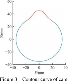
In this paper, according to the overall size of the intermittent type distributor, the base radius of the cam is designed as 35 mm and the radius of plunger roller is 10 mm. Matlab GUI human-computer interaction platform is applied to obtain the contour curve of the cam based on the mathematical model of the cam by using “for” loop for numeric iterations[17-19] as shown in Figure 3.
Figure 3 Contour curve of cam
2.4 Three-dimensional modeling of cam
In order to verify the rationality of the cam design, a three-dimensional modeling of cam was conducted. The data point coordinates of the cam contour curve will be exported automatically and saved in text file (.txt) format through Matlab GUI development platform
Txt file containing the data point coordinates of the cam contour curve is re-saved in the Pro/E coordinate point file (.ibl). And the codes which make the points become the lines were written as flows: open, arclength, begin section, begin curve. All these statements were written in the beginning of the data point coordinates.
Open the proe5.0 software, enter the three-dimensional solid configuration interface, click the “curve” and “self-file” buttons successively, import the modified .ibl file into the Pro/E sketches
interface, get the cam three-dimensional model through the drawing command[16], as shown in Figure 4.
Figure 4 Three-dimensional model of cam
2.5 Force analysis of cam mechanism
(1) Statics analysis
In order to verify the designed cam can meet various mechanical characteristics such as good ability to withstand pressures, sensitive actions and compact size, the force analysis[20-22] was carried out firstly as shown in Figure 5.
Figure 5 Force analysis diagram of roller follower According to the conditions applicable to force balance, the following equations can be obtained:
∑Fx=0 ∑Fy=0 ∑M=0 (7)
1 1 2 2
1 1 2 2
1 2 1
sin( ) ( ) cos 0
cos( ) ( )sin 0
cos ( )sin( ) 0
F a φ R R φ
Q F a φ R R φ
LR φ F L b a φ
+ − − = ⎧ ⎪ − + + − = ⎨ ⎪ − + + = ⎩ (8)
where, φ1=arctanf1, φ2=arctanf2.
The solutions to the above equations are obtained:
1
1
2
( )sin( )
cos
F L b a φ
R
L φ
+ +
= (9)
1 2
2
sin( )
cos
Fb a φ
R
L φ +
= (10)
1 1 2
2
cos( ) (1 b)sin( ) tan
Q F a φ a φ φ
L
⎡ ⎤
= ⎢ + − + + ⎥
⎣ ⎦ (11)
1 1 2
2
cos( ) (1 )sin( ) tan
Q F
b
a φ a φ φ
L = ⎡ + − + + ⎤ ⎢ ⎥ ⎣ ⎦ (12)
where, a is the pressure angle of the cam mechanism in the corresponding figures, rad; R1 and R2 are the total counter-force of
between two supports of the guideway, m; b is the overhang length of the follower, m; φ1 is the friction angle between the follower and
the cam contour line, rad; φ2 is the friction angle between the
follower and the guideway, rad.
Based on the above theoretical analysis, some conclusions are drawn. On equal conditions, the greater the a is, the smaller the denominator is and the F will be.
(2) Dynamic analysis
The dynamic analysis was conducted on the cam on the working conditions based on the D'Alembert principle[23,24] and there are two main situations: 1) The cam is not subjected to the pressure of the plunger; 2) The cam is subjected to the pressure of the plunger. For the first condition, the dynamic analysis was conducted for the cam and the frictional resistance between the roller and the cam was ignored, as shown in Figure 6 [25-27].
Figure 6 Force-analysis diagram of cam in the stage of the near repose
The equilibrium equations under the first condition are listed:
1
cos 0
sin 0
cos 0
x I
y I
F F θ
F F θ mg M M mge θ
⎧ + =
⎪ + − =
⎨
⎪ − − =
⎩
(13)
The following solutions could be obtained:
1 cos
sin cos
x I
y I
F F θ
F mg F θ
M M mge θ ⎧ = −
⎪ = −
⎨
⎪ = −
⎩
(14)
where, FI=meω2; FI is the inertial force, N; m is the mass of the
cam and the camshaft, kg; θ is the angle between the inertial force and the horizontal line, (°); Fx is the horizontal binding force, N; Fy
is the vertical binding force, N; M1 is the resisting moment, Nm; e
is eccentricity, m; O is the point of rotation center; O1 is the mass
center of the cam; M is the driving moment, Nm; ω is the rotational speed of the cam, rad/s.
According to Equation (14), the following rules are obtained. When the inertial force is in the first or fourth quadrant, the direction of Fx is opposite to that of the inertia force. Its value
gradually increased, and then gradually decreased. In the x-axis positive direction, it reached maximum value which is meω2. In the y-axis negative direction, it reached the minimum value which is 0; The value of Fy gradually increased. In the y-axis negative
direction, it reached its maximum value which is mg+ meω2. The direction of M1 is opposite to that of driving moment. It gradually
decreased and then gradually increased. In the x-axis positive direction, it reached its minimum value which is M–mgecosθ. In the y-axis negative direction, it reached its maximum value which is M. Similarly, the rules of inertial force when it is in the second or thirdly quadrant can also be obtained.
On the second condition where the cam is subjected to the
pressure of the plunger, the dynamic analysis was also conducted, as shown in Figure 7.
Figure 7 Force-analysis diagram of cam in the rise travel The equilibrium equations on the second condition are listed:
2
cos sin 0
sin cos 0
cos sin 0
x I N
y I N
N
F F θ F a F F θ mg F a M M mge θ F a H
⎧ + + =
⎪ + ⋅ ⋅ =
⎨
⎪ ⋅ ⋅ ⋅ ⋅ =
⎩
(15)
The solutions can be obtained,
2
( cos sin )
cos sin
cos sin
x I N
y N I
N
F F θ F a F mg F a F θ
M M mge θ F a H
⎧ = − +
⎪ = + −
⎨
⎪ = − − ⋅
⎩
(16)
where, FN is the pressure of the cam subjected from the plunger, N;
a is the pressure angle of the cam mechanism in the corresponding figure,°; M2 is the resisting moment, Nm; H is the distance from the
pressure surface to the rotation axis, m.
If the cam is subjected to the pressure from plunger, the values of Fx, Fy and M2 are mainly related to FN, and increase with it.
3 Cam’s performance testing
3.1 Conditions and methods
In order to verify the superior performance of the machine, the cam of intermittent type distributor was tested at Northeast Agricultural University. As shown in Figure 8, the distributor 4 was connected with the fertilizer pipeline, and it was installed on the soil bin car, which was fixed on the original position. The motor 2 drove the hydraulic pump 6, and the liquid fertilizer which was discharged from the liquid tank 5 went into the intermittent type distributor 4 with a certain pressure and then was sprayed into the soil by the fertilizer-spraying needle. The motor 1 drove the camshaft through the coupling to achieve the functions of distribution valve, i.e. spraying and stopping the spraying of the liquid fertilizer. The motors were controlled by the frequency converter 3. The testbed for the intermittent type distributor was shown in Figure 8.
1. Motor 1 2. Motor 2 3. Frequency conversion cabinet 4. Intermittent type distributor 5. Liquid tank 6. Hydraulic pump
of fertilizer applied per time, the speed of the camshaft was set as a fixed value 50 r/min, and the pump pressure was considered as an influencing factor. The amount of fertilizer was 20 mL and it was taken as an impact indicator. The pump pressure was set to 5 levels, 0.2 MPa, 0.3 MPa, 0.4 MPa, 0.5 MPa and 0.6 MPa respectively. Five trials were repeated at each level. The amount of fertilizer was measured for 10 times and the average value was calculatted. The computational formula for the sprayed fertilizer per time can be obtained as follows:
10
1 10
i i
Q
Q=
∑
= (17)where, Qi is the single amount of fertilizer at the spray mouth, mL;
Q is the average amount of fertilizer per time, mL.
3.2 Results and analysis
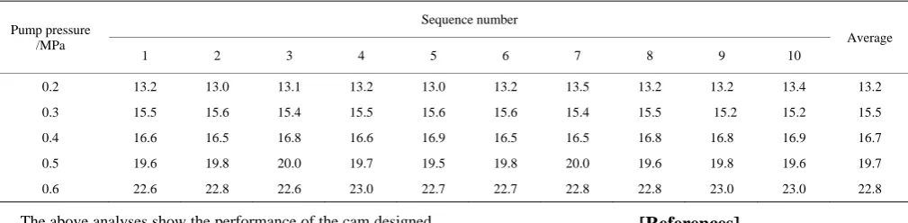
The test results are shown at Table 1. It can be seen from the table that the amount of fertilizer measured each time at the spray mouth is basically the same. When the pump pressure is at 0.5 MPa, the amount of fertilizer can meet basically the agronomic
requirement, i.e. 20 mL. When the pump pressure is less than 0.5 MPa, the flow of the liquid fertilizer is insufficient. The main reasons are as follows. When the rotational angle of the cam is over 8.6°, the pressure energy and the kinetic energy of liquid fertilizer are too small to open the pressure valve, so the measured amount of fertilizer is small. Besides, no fertilizer is sprayed immediately when the needle gets into the soil, which results in time lag. When the pump pressure is equal to 0.5 MPa, the flow of the liquid fertilizer is close to 60.65 mL. The pressure valve can be opened because the pressure potential energy and kinetic energy of the liquid fertilizer are equal to the elastic potential energy of the pressure valve. When the cam rotates over 8.6°, the displacement of the plunger is 0.84 mm so that the needle can spray fertilizer timely and accurately. When the pump pressure is greater than 0.5 MPa, the flow of the liquid fertilizer is too much. The main reason is that the pressure potential energy and kinetic energy of the liquid fertilizer are larger than the elastic potential of the pressure valve when the cam rotates over 8.6°, which leads to the earlier fertilizer-spraying operation.
Table 1 Result of the stability of fertilizer application
Unit: mL Pump pressure
/MPa
Sequence number
Average 1 2 3 4 5 6 7 8 9 10
0.2 13.2 13.0 13.1 13.2 13.0 13.2 13.5 13.2 13.2 13.4 13.2
0.3 15.5 15.6 15.4 15.5 15.6 15.6 15.4 15.5 15.2 15.2 15.5
0.4 16.6 16.5 16.8 16.6 16.9 16.5 16.5 16.8 16.8 16.9 16.7
0.5 19.6 19.8 20.0 19.7 19.5 19.8 20.0 19.6 19.8 19.6 19.7
0.6 22.6 22.8 22.6 23.0 22.7 22.7 22.8 22.8 23.0 23.0 22.8
The above analyses show the performance of the cam designed based on theoretical analysis and calculation. The test results indicate that this mechanism can make the needle spray fertilizer timely and accurately as soon as it gets into the soil.
4 Conclusions
Bernoulli equation was used to optimize the motion angles of cam rise travel and return travel, and the cam contour line was obtained based on the Matlab GUI platform, which enabled the fertilizer-spraying needle to spray fertilizer accurately.
In order to provide a theoretical basis for reducing vibration of the cam mechanism, the change rules of the force and the resistance moment were obtained based on the statics and dynamics analysis. By applying the Pro/E software, a three-dimensional model of the cam of the intermittent type distributor was established and the rationality of the cam was verified.
In the test, the average amount of fertilizer is 19.7 mL when the pump pressure is 0.5 MPa and the rotational speed of the camshaft is 50 r/min. It shows the optimized cam can achieve the anticipated effects, that is, the spray fertilizer-spraying needle sprays liquid fertilizer as soon as it gets into the soil and stops spraying immediately when it gets out of the soil so as to spray fertilizer accurately.
Acknowledgements
This research was supported by the National Natural Science Foundation of China (Grant No.51675093) and “Young Talents” Project of Northeast Agricultural University (Grant No.18QC19).
[References]
[1] Vieira-Megda M X, Mariano E, Leite J M, Franco H C J, Vitti A C, Megda M M. Contribution of fertilizer nitrogen to the total nitrogen extracted by sugarcane under Brazilian field conditions. Nutr. Cycl. Agroecosyst, 2015; 101: 241–257.
[2] Costa M C G, Vitti G C, Cantarella H. N-NH3 losses from nitrogen
sources applied over unburned sugarcane straw. Rev. Bras. Ciência do Solo, 2003; 27: 631–637.
[3] Liu T Q, Fan D J, Zhang X X, Chen J, Li C F, Cao C G. Deep placement of nitrogen fertilizers reduces ammonia volatilization and increases nitrogen utilization efficiency in no-tillage paddy fields in central China. Field Crops Res, 2015; 184: 80–90.
[4] Da Silva M J, Junqueira Franco H C, Graziano Magalhães P S. Liquid fertilizer application to ratoon cane using a soil punching method. Soil & Tillage Research, 2017; 165: 279–285.
[5] Niemoeller B, Harms H H. Lang T. Injection of liquids into the soil with a high-pressure jet. Agric. Eng. Int. CIGR J, 2011; 13: 1–15.
[6] Rahman S, Chen Y, Lobb D. Soil movement resulting from sweep type liquid manure injection tools. Biosystems Engineering, 2005; 91(3): 379–392.
[7] He J N. Study on working principle and experiment of work components of liquid fertilizer injection type. Harbin: Northeast Agricultural University, 2013. (in Chinese)
[8] Wang J W, Pan Z W, Zhou W Q, Wang J F, He J N, Lang C L. Design and test of SYL-2 type liquid variable fertilizer. Transactions of the CSAM, 2015; 46(7): 53–58. (in Chinese)
[9] Wang J W, He J N, Pan Z W, Wang J F, Lang C L. Kinematic analysis and simulation of liquid fertilizer distributor’s cam for liquid fertilizer applicator. Transactions of the CSAM, 2013; 44(4): 77–82. (in Chinese) [10] Pan Z W. Design and experimental study of liquid feritilizer pripeline
converter and transporting liquid fertilizer system. Harbin: Northeast Agricultural University, 2014. (in Chinese)
[12] Wang J W, Pan Z W, Yang X L, Liu Y J, Zhang C F, Wang J F. Design and experiment of rotary converter of liquid fertilizer. Transactions of the CSAM, 2014; 45(10): 110–115. (in Chinese)
[13] Mueller M, Hoffmann M, Huesing M. Using servo-drives to optimize the transmission angle of cam mechanism. Mechanism and Machine Theory, 2019; 135: 165–175.
[14] Jin X, Li D Y, Ma H, Ji J T, Zhao K X, Pang J. Development of single row automatic transplanting device for potted vegetable seedlings. Int J Agric & Biol Eng, 2018; 11(3): 67–75.
[15] Shang X, Xia B Z, Ren S Y. Design and optimization of CAM connecting rod system in high-speed drives based on dynamic characteristics and mathematical model. Proceedings of the Institution of Mechanical Engineers Part K: Journal of Multi-Body Dynamics, 2018; 232(1): 113–128.
[16] Quaglia G, Nisi M. Design of a self-leveling cam mechanism for a stair climbing wheelchair. Mechanism and Machine Theory, 2017; 112: 84–104.
[17] Chen J. Matlab collection. Second Edition. Beijing: Electronic Industry Press, 2010. (in Chinese)
[18] Zhou H J. Modern design of cam mechanism. Shanghai: Shanghai Jiaotong University Press, 2005. (in Chinese)
[19] Liu G D, Chen G H, Pan Z X, Zhao N. Application of the cubic spline interpolation function in the kinematic analysis of cam mechanism. Journal of Mechanical Transmission, 2007; 31(5): 53–56. (in Chinese) [20] Yi J J, Chen Y M, Zhang W Q. Line-contact cam design and load
analysis of rope-biting mechanism of knotter. Transactions of the CSAM, 2016; 47(7): 224–231. (in Chinese)
[21] Zhou C J, Hu B, Chen S Y, Ma L. Design and analysis of high-speed cam mechanism using Fourier series. Mechanism and Machine Theory, 2016; 104: 118–129.
[22] Yu J W, Luo H, Hu J Z. Reconstruction of high-speed cam curve based on high-order differential interpolation and shape adjustment. Applied Mathematics and Computation, 2019; 356: 272–281.
[23] Li M, Cheng W, Xie R L. Design and experimental validation of a cam-based constant-force compression mechanism with friction considered. Proceedings of the Institution of Mechanical Engineers Part K-Journal of Multi-Body Dynamics, 2019; 233(11): 3873–3887.
[24] Zhang N, Chen N, Ouyang T C, Wang P, Huang H Z. Mathematical modeling and optimization of cam mechanism in delivery system of an offset press. Mechanism and Machine Theory, 2017; 110: 100–114. [25] Lin D Y, Hou B J, Lan C C. A balancing cam mechanism for minimizing
the torque fluctuation of engine camshafts. Mechanism and Machine Theory, 2017; 108: 160–175.
[26] Jin G G, Wei Z, Qin K X, Zhang Y Y. Dynamic analysis and modal truncation of high-speed cam mechanism. Journal of Mechanical Engineering, 2015; 51(13): 227–233. (in Chinese)