University of New Orleans Theses and
Dissertations Dissertations and Theses
12-15-2006
Usability Studies with Virtual and Traditional Computer Aided
Usability Studies with Virtual and Traditional Computer Aided
Design Environments
Design Environments
Syed Adeel AhmedUniversity of New Orleans
Follow this and additional works at: https://scholarworks.uno.edu/td
Recommended Citation Recommended Citation
Ahmed, Syed Adeel, "Usability Studies with Virtual and Traditional Computer Aided Design Environments" (2006). University of New Orleans Theses and Dissertations. 477.
https://scholarworks.uno.edu/td/477
Usability Studies with Virtual and Traditional Computer Aided Design Environments
A Dissertation
Submitted to Graduate faculty of the University of New Orleans in partial fulfillment of the requirements for the degree of
Doctor of Philosophy in
Engineering and Applied Science
by
Syed Adeel Ahmed B.S. Osmania University, 1997 M.S. University of New Orleans, 2001
Dedication
This dissertation is dedicated to Almighty God, my mother (Shah Zamani Begum), my father (Syed Shakeel Ahmed), my sister (Dr. Asra Tabassum & her kids), my wife (Naveedunnisa Ahmed), my kids (Zoya, Neha, Mukhtadeer/Sohaib Ahmed), my teachers, all my well wishers/friends, and my entire family.
Acknowledgements
I am most grateful to the Office of Naval Research (ONR) for their support of the research through GCRMTC (Dr. Alley Butler & Dr. Kurt Satter), Dillard University (Dr. Keith Wismar) and to the Naval Research Laboratory (NRL) for the VR equipment provided to the University of New Orleans through Department of Defense (DoD) Property Disposal.
Several University of New Orleans staff and graduate assistants must be credited with much of the CAVETM systems installation, technical support, and the seemingly endless task of test administration. These exceedingly helpful individuals include: Edward Williams, Steve Attaya, Arthur Butz, Dr. Greg Dobson, and Mathew Hamey.
I must also recognize all my Dillard University students who participated as test subjects in this research. Their assistance was invaluable and sincerely appreciated.
I thank Dr. Kurt Satter, Dr. Alley Butler and their whole families for their precious support. Without their help and encouragement little, if any, progress would have been made.
I also thank the Department Chair, William Lannes, for championing the PhD program and for his support and direction into the administrivia of terminal degree pursuit. Without his guidance and support little progress would have been made.
Table of Contents
LIST OF TABLES... V
LIST OF FIGURES ...VIII
ABSTRACT...XI
KEYWORDS...XI
1.
INTRODUCTION ... 1
1.1 Background...1
1.2 VE Interaction: Technology...6
1.2.1 Inputs...6
1.2.2 Output ...9
1.2.3 Immersive Virtual Environments and Their Characteristics ...10
1.3 Interactions in a Virtual Environment (VE)...11
1.4 Interaction Devices for Virtual Reality...13
1.4.1 Head-Mounted Display (HMD)...13
1.4.2 CAVETM...14
1.4.3 Data Gloves...15
1.4.4 Pinch Gloves ...15
1.4.5 Joystick, Wand, or Flightstick ...16
1.4.6 Shared Virtual Environments...17
1.4.7 ImmersaDesk ...18
1.4.8 CrystalEyes ...20
2.
GESTURAL INTERFACE... 22
2.1 What is a Gesture ...22
2.2 How to use gestures? ...25
2.3 Usability and Ease of Use of Gestures...27
2.4 The Role of Non-Symbolic Gestures...30
2.5 Task-Based Evaluation of Gesture Interactions...31
2.6 Gesture in Selection ...32
2.7 Gesture in Manipulation ...34
2.8 Gesture in Travel...35
2.9 Gesture in Traditional User Interfaces...38
2.10 Guidelines for the Design of Gesture Command Sets ...40
3. PROJECT DESCRIPTION ... 44
3.1 Background………..………44
3.2 User Centered Development………..………..49
3.3 Gestural, Voice, and Multimodal Virtual Interfaces………....52
3.4 General Experimental Procedure………..55
4 BECNMARK 1 (NAVIGATION)... 63
4.1 Description...63
4.2 Pass-to-pass Improvements in Elapsed Times...63
4.3 B1-Pass-to-Pass Comparison of Elapsed Times Analysis...64
4.4 Elapsed Times Detailed Statistical Analysis...65
4.5 Mann-Whitney Test ...67
4.6 Pass 3 Statistics ...67
4.7 User Subjective Overall Environment Ratings ...68
4.8 B1-Pass to Pass Comparison of Overall Impressions Ratings Analysis...71
5 BENCHMARK 2 (FIND AND REPAIR MANIPULATION)... 72
5.1 Description...72
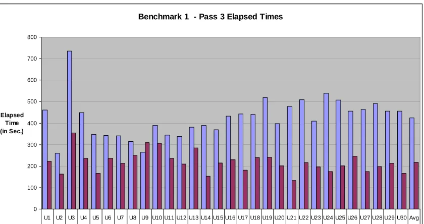
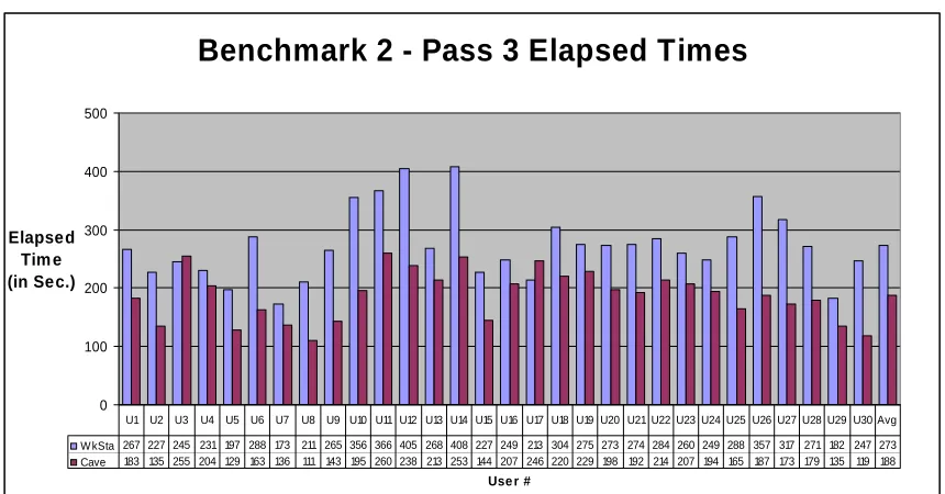
5.2 Benchmark 2 – pass 3 Elapsed timing analysis ...73
5.3 Pass-to-Pass Comparison of Elapsed Times Analysis ...74
5.4 Detailed Statistical Analysis ...74
5.5 Pass 3 Statistical Analysis...74
5.6 User Subjective Overall Environment Ratings ...76
5.7 Benchmark 2 – pass 3 Overall Impressions ratings analysis ...76
5.8 B2-Pass to Pass Comparison Overall Impressions Ratings Analysis ...78
6. BENCHMARK 3 (SPATIAL AWARENESS) ... 79
6.1 Description...79
6.2 Benchmark 3, Pass 3, Part 1 & 2 Placement Offsets Analysis ...81
6.3 Detailed Statistical Analysis ...84
6.4 Benchmark 3Pass 3 Statistics...84
6.5 B3p3-2off –Benchmark 3 Pass 3 Descriptive Statistics ...84
6.6 Benchmark 3 pass 3 Overall Impressions Ratings Analysis...86
6.7 Detailed Statistical Analysis ...87
6.8 Benchmark 3 Pass 3 Overall Impressions Ratings Statistics ...87
7. BENCHMARK 4 (FAULT IDENTIFICATION) ... 91
7.1 Description...91
7.2 Benchmark 4, Pass 3, faults count Analysis ...92
7.3 B4p3- Benchmark 4 Pass 3 Descriptive Statistics ...94
7.4 Benchmark 3 pass 3 Overall Impressions Ratings Analysis...94
7.5 Detailed Statistical Analysis ...95
7.6 Benchmark 4 Pass 3 Overall Impressions Ratings Statistics ...95
8. CONCLUSIONS AND RECOMMENDATIONS ... 98
8.1 Enhancements for Further Study ...99
8.2 Tracking Map...100
8.3 Future Work ...100
References ... 103
Appendix A...116
Appendix B ...141
Appendix C ...166
Appendix D...195
Appendix 1 – Course Completion Certificates ...220
Appendix 2 – Consent Form...223
Appendix 3 – Approval for Human Subjects...228
Appendix 4 – Survey used by Satter (2005) ...230
Appendix 5 – Medical Condition Questionnaire ...232
Appendix 6 – Dillard University Flyer ...234
List of Tables
Table 4.1: B1-Pass-to-Pass Comparison of Elapsed Times...65
Table 4.2: B1p3Tim Elapsed Times ...67
Table 4.3: B1p3Ovr Overall Impressions Ratings...70
Table 4.4: B1-Pass to Pass Comparison of Overall Impressions Ratings...71
Table 5.1: Pass-to-Pass Comparison of Elapsed Times...74
Table 5.2: B2p3Tim Elapsed Times Statistics...75
Table 5.3: B2p3Ovr Overall Impressions Ratings...77
Table 5.4: B2-Pass to Pass Comparison Overall Impressions Ratings...78
Table 6.1: B3p3-1off Pass 3-Icon 1 Offsets...82
Table 6.2: B3p3-2off Pass 3-Icon 2 Offsets...85
Table 6.3: B3p3Ovr Pass 3 Overall Impressions Ratings Descriptive Statistics...88
Table 6.4: B3I1 pass-to-pass Comparison of Offset distances ...89
Table 6.5: B3I2 pass-to-pass Comparison of Offset distances ...89
Table 6.6: B3 Overall Impressions Ratings pass to pass Comparison...90
Table 7.1: B4p3 Faults Count Statistics...93
Table 7.2: B4p3Ovr Overall Impressions Ratings Statistics ...96
Table 7.3: B4 Pass-to-Pass Comparison of Faults Count ...96
Table 7.4: B4 Overall Impressions Ratings Pass to Pass Comparison ...97
Table A-1: B1p1Tim Elapsed Times Statistics...117
Table A-2: B1p1Nav Navigation Ratings Statistics ...118
Table A-3: B1p1Loc Locating Ratings Statistics ...119
Table A-4: B1p1Mov Movement Ratings Statistics...120
Table A-5: B1p1Gen General Impressions Ratings Statistics ...121
Table A-6: B1p1Ovr Overall Impressions Ratings Statistics ...122
Table A-7: B1p2Tim Elapsed Times Statistics...123
Table A-8: B1p2Nav Navigation Ratings Statistics ...124
Table A-9: B1p2Loc Locating Ratings Statistics ...125
Table A-10: B1p2Mov Movement Ratings Statistics...126
Table A-11: B1p2Gen General Impressions Ratings Statistics ...127
Table A-12: B1p2Ovr Overall Impressions Ratings Statistics ...128
Table A-13: B1p3Tim Elapsed Times Statistics...129
Table A-14: B1p3Nav Navigation Ratings Statistics ...130
Table A-15: B1p3Loc Locating Ratings Statistics ...131
Table A-16: B1p3Mov Movement Ratings Statistics...132
Table A-17: B1p3Gen General Impressions Ratings Statistics ...133
Table A-18: B1p3Ovr Overall Impressions Ratings Statistics ...134
Table A-19: B1-3pAvgTim Elapsed Times Statistics ...135
Table A-20: B1-3pAvgNav Navigation Ratings Statistics ...136
Table A-21: B1-3pAvgLoc Locating Ratings Statistics ...137
Table A-22: B1-3pAvgMov Movement Ratings Statistics...138
Table A-23: B1-3pAvgGen General Impressions Ratings Statistics...139
Table A-24: B1-3pAvgOvr Overall Impressions Ratings Statistics ...140
Table B-1: B2p1Tim Elapsed Times Statistics...142
Table B-3: B2p1Loc Locating Ratings Statistics...144
Table B-4: B2p1Mov Movement Ratings Statistics ...145
Table B-5: B2p1Gen General Impressions Ratings Statistics ...146
Table B-6: B2p1Ovr Overall Impressions Ratings Statistics ...147
Table B-7: B2p2Tim Elapsed Times Statistics...148
Table B-8: B2p2Nav Navigation Ratings Statistics...149
Table B-9: B2p2Loc Locating Ratings Statistics...150
Table B-10: B2p2Mov Movement Ratings Statistics ...151
Table B-11: B2p2Gen General Impression Ratings Statistics...152
Table B-12: B2p2Ovr Overall Impression Ratings Statistics ...153
Table B-13: B2p3Tim Elapsed Times Statistics...154
Table B-14: B2p3Nav Navigation Ratings Statistics...155
Table B-15: B2p3Loc Locating Ratings Statistics...156
Table B-16: B2p3Mov Movement Ratings Statistics ...157
Table B-17: B2p3Gen General Impressions Ratings Statistics ...158
Table B-18: B2p3Ovr Overall Impressions Ratings Statistics ...159
Table B-19: B2-3pAvgTim Elapsed Times Statistics...160
Table B-20: B2-3pAvgNav Navigation Ratings Statistics ...161
Table B-21: B2-3pAvgLoc Locating Ratings Statistics ...162
Table B-22: B2-3pAvgMov Movement Ratings Statistics...163
Table B-23: B2-3pAvgGen General Impressions Ratings Statistics ...164
Table B-24: B2-3pAvgOvr Overall Impressions Ratings Statistics ...165
Table C-1: B3p1-1off Pass 1- Icon 1 Offsets Statistics ...167
Table C-2: B3p1-2off Pass 1- Icon 2 Offsets Statistics ...168
Table C-3: B3p1Nav- Pass 1- Navigation Ratings Statistics...169
Table C-4: B3p1Loc- Pass 1- Locating Ratings Statistics...170
Table C-5: B3p1Mov- Pass 1- Movement Ratings Statistics ...171
Table C-6: B3p1Gen- Pass 1- General Impressions Ratings Statistics...172
Table C-7: B3p1Ovr- Pass 1 Overall Impressions Ratings Statistics ...173
Table C-8: B3p2-1off- Pass 2-Icon 1 Offsets Statistics...174
Table C-9: B3p2-2off- Pass 2-Icon 2 Offsets Statistics...175
Table C-10: B3p2Nav Pass 2-Navigation Ratings Statistics ...176
Table C-11: B3p2Loc Pass 2 Locating Ratings Statistics ...177
Table C-12: B3p2Mov Pass 2 Movement Ratings Statistics ...178
Table C-13: B3p2Gen Pass 2 General Impressions Ratings Statistics ...179
Table C-14: B3p2Ovr Pass 2 Overall Impressions Ratings Statistics ...180
Table C-15: B3p3-1off Pass 3-Icon 1 Offsets Statistics ...181
Table C-16: B3p3-2off Pass 3-Icon 2 Offsets Statistics ...182
Table C-17: B3p3Nav Pass 3 Navigation Ratings Statistics ...183
Table C-18: B3p3Loc Pass 3 Locating Ratings Statistics ...184
Table C-19: B3p3Mov Pass 3 Movement Ratings Statistics ...185
Table C-20: B3p3Gen Pass 3 General Impressions Ratings Statistics ...186
Table C-21: B3p3Ovr Pass 3 Overall Impressions Ratings Statistics ...187
Table C-22: B3-3pA-1Off 3 Pass Avg. Part 1 Offsets Statistics ...188
Table C-25: B3-3pALoc 3 Pass Avg. Locating Ratings Statistics ...191
Table C-26: B3-3pAmov 3 Pass Avg. Movement Ratings Statistics ...192
Table C-27: B3-3pAgen 3 Pass Avg. General Impressions Ratings Statistics ...193
Table C-28: B3-3pAOvr 3 Pass Avg. Overall Impressions Ratings Statistics ...194
Table D-1: B4p1 Faults Count Statistics ...196
Table D-2: B4p1Nav Navigation Ratings Statistics ...197
Table D-3: B4p1Loc Locating Ratings Statistics ...198
Table D-4: B4p1Mov Movement Ratings Statistics...199
Table D-5: B4p1Gen General Impressions Ratings Statistics ...200
Table D-6: B4p1Ovr Overall Impressions Ratings Statistics ...201
Table D-7: B4p2 Faults Count Statistics ...202
Table D-8: B4p2Nav Navigation Ratings Statistics ...203
Table D-9: B4p2Loc Locating Ratings Statistics ...204
Table D-10: B4p2Mov Movement Ratings Statistics...205
Table D-11: B4p2Gen General Impression Ratings Statistics...206
Table D-12: B4p2Ovr Overall Impression Ratings Statistics...207
Table D-13: B4p3 Faults Count Statistics ...208
Table D-14: B4p3Nav Navigation Ratings Statistics ...209
Table D-15: B4p3Loc Locating Ratings Statistics ...210
Table D-16: B4p3Mov Movement Ratings Statistics...211
Table D-17: B4p3Gen General Impressions Ratings Statistics ...212
Table D-18: B4p3Ovr Overall Impressions Ratings Statistics ...213
Table D-19: B4-3pAvg Faults Count Statistics ...214
Table D-20: B4-3pAvgNav Navigation Ratings Statistics ...215
Table D-21: B4-3pAvgLoc Locating Ratings Statistics ...216
Table D-22: B4-3pAvgMov Movement Ratings Statistics...217
Table D-23: B4-3pAvgGen General Impressions Ratings Statistics...218
List of Figures
Figure 1.1: A Head Mounted Display (HMD)...14
Figure 1.2: Schematic of the CAVETM System ...14
Figure 1.3: Data Gloves ...15
Figure 1.4: Application of Data Gloves...15
Figure 1.5: Pinch Glove System ...16
Figure 1.6: Flightstick...17
Figure 1.7: Networked Virtual Environments ...18
Figure 1.8: The Immersadesk System...19
Figure 1.9: Crystal Eye Glasses...21
Figure 3.1: Synthesis of a Design……….………..47
Figure 3.2: Completed Design……….………...47
Figure 3.3: Wand Gestural Interface with the Adaptable ...48
Figure 3.4: Voice & Glove Gestural Interface with the Adaptable ...48
Figure 3.5: Designer Centered Design and Evaluation Process ...51
Figure 4.1: B1p3Tim Elapsed Times ...64
Figure 4.2: B1p3Ovr Overall Impressions Ratings...69
Figure 5.1: B2p3Tim Elapsed Times ...73
Figure 5.2: B2p3Ovr Overall Impressions Ratings...77
Figure 6.0: Icon...80
Figure 6.1: B3p3-1off Pass 3-Icon 1 Offsets ...82
Figure 6.2: B3p3-2off Pass 3-Icon 2 Offsets ...83
Figure 6.3: B3p3Ovr Pass 3 Overall Impressions Ratings ...86
Figure 7.1: B4p3 Faults Count...93
Figure 7.2: B4p3Ovr Overall Impressions Ratings...96
Figure A-1: B1p1Tim Elapsed Times...117
Figure A-2: B1p1Nav Navigation Ratings ...118
Figure A-3: B1p1Loc Locating Ratings ...119
Figure A-4: B1p1Mov Movement Ratings ...120
Figure A-5: B1p1Gen General Impressions Ratings ...121
Figure A-6: B1p1Ovr Overall Impressions Ratings ...122
Figure A-7: B1p2Tim Elapsed Times...123
Figure A-8: B1p2Nav Navigation Ratings ...124
Figure A-9: B1p2Loc Locating Ratings ...125
Figure A-10: B1p2Mov Movement Ratings ...126
Figure A-11: B1p2Gen General Impressions Ratings ...127
Figure A-12: B1p2Ovr Overall Impressions Ratings ...128
Figure A-13: B1p3Tim Elapsed Times...129
Figure A-14: B1p3Nav Navigation Ratings ...130
Figure A-15: B1p3Loc Locating Ratings ...131
Figure A-16: B1p3Mov Movement Ratings ...132
Figure A-17: B1p3Gen General Impressions Ratings ...133
Figure A-18: B1p3Ovr Overall Impressions Ratings ...134
Figure A-21: B1-3pAvgLoc Locating Ratings ...137
Figure A-22: B1-3pAvgMov Movement Ratings...138
Figure A-23: B1-3pAvgGen General Impressions Ratings ...139
Figure A-24: B1-3pAvgOvr Overall Impressions Ratings ...140
Figure B-1: B2p1Tim Elapsed Times ...142
Figure B-2: B2p1Nav Navigation Ratings...143
Figure B-3: B2p1Loc Locating Ratings...144
Figure B-4: B2p1Mov Movement Ratings ...145
Figure B-5: B2p1Gen General Impressions Ratings ...146
Figure B-6: B2p1Ovr Overall Impressions Ratings...147
Figure B-7: B2p2Tim Elapsed Times ...148
Figure B-8: B2p2Nav Navigation Ratings...149
Figure B-9: B2p2Loc Locating Ratings...150
Figure B-10: B2p2Mov Movement Ratings ...151
Figure B-11: B2p2Gen General Impression Ratings ...152
Figure B-12: B2p2Ovr Overall Impression Ratings ...153
Figure B-13: B2p3Tim Elapsed Times ...154
Figure B-14: B2p3Nav Navigation Ratings...155
Figure B-15: B2p3Loc Locating Ratings...156
Figure B-16: B2p3Mov Movement Ratings ...157
Figure B-17: B2p3Gen General Impressions Ratings ...158
Figure B-18: B2p3Ovr Overall Impressions Ratings...159
Figure B-19: B2-3pAvgTim Elapsed Times...160
Figure B-20: B2-3pAvgNav Navigation Ratings ...161
Figure B-21: B2-3pAvgLoc Locating Ratings ...162
Figure B-22: B2-3pAvgMov Movement Ratings ...163
Figure B-23: B2-3pAvgGen General Impressions Ratings ...164
Figure B-24: B2-3pAvgOvr Overall Impressions Ratings ...165
Figure C-1: B3p1-1off Pass 1- Icon 1 Offsets ...167
Figure C-2: B3p1-2off Pass 1- Icon 2 Offsets ...168
Figure C-3: B3p1Nav- Pass 1- Navigation Ratings...169
Figure C-4: B3p1Loc- Pass 1- Locating Ratings...170
Figure C-5: B3p1Mov- Pass 1- Movement Ratings ...171
Figure C-6: B3p1Gen- Pass 1- General Impressions Ratings...172
Figure C-7: B3p1Ovr- Pass 1 Overall Impressions Ratings ...173
Figure C-8: B3p2-1off- Pass 2-Icon 1 Offsets...174
Figure C-9: B3p2-2off- Pass 2-Icon 2 Offsets...175
Figure C-10: B3p2Nav Pass 2-Navigation Ratings ...176
Figure C-11: B3p2Loc Pass 2 Locating Ratings...177
Figure C-12: B3p2Mov Pass 2 Movement Ratings ...178
Figure C-13: B3p2Gen Pass 2 General Impressions Ratings ...179
Figure C-14: B3p2Ovr Pass 2 Overall Impressions Ratings ...180
Figure C-15: B3p3-1off Pass 3-Icon 1 Offsets ...181
Figure C-16: B3p3-2off Pass 3-Icon 2 Offsets ...182
Figure C-17: B3p3Nav Pass 3 Navigation Ratings...183
Figure C-19: B3p3Mov Pass 3 Movement Ratings ...185
Figure C-20: B3p3Gen Pass 3 General Impressions Ratings ...186
Figure C-21: B3p3Ovr Pass 3 Overall Impressions Ratings ...187
Figure C-22: B3-3pA-1Off 3 Pass Avg. Part 1 Offsets ...188
Figure C-23: B3-3pA-1Off 3 Pass Avg. Part 2 Offsets ...189
Figure C-24: B3-3pAnav 3 Pass Avg. Navigation Ratings ...190
Figure C-25: B3-3pALoc 3 Pass Avg. Locating Ratings ...191
Figure C-26: B3-3pAmov 3 Pass Avg. Movement Ratings ...192
Figure C-27: B3-3pAgen 3 Pass Avg. General Impressions Ratings ...193
Figure C-28: B3-3pAOvr 3 Pass Avg. Overall Impressions Ratings ...194
Figure D-1: B4p1 Faults Count...196
Figure D-2: B4p1Nav Navigation Ratings ...197
Figure D-3: B4p1Loc Locating Ratings ...198
Figure D-4: B4p1Mov Movement Ratings ...199
Figure D-5: B4p1Gen General Impressions Ratings ...200
Figure D-6: B4p1Ovr Overall Impressions Ratings ...201
Figure D-7: B4p2 Faults Count...202
Figure D-8: B4p2Nav Navigation Ratings ...203
Figure D-9: B4p2Loc Locating Ratings ...204
Figure D-10: B4p2Mov Movement Ratings ...205
Figure D-11: B4p2Gen General Impression Ratings...206
Figure D-12: B4p2Ovr Overall Impression Ratings...207
Figure D-13: B4p3 Faults Count...208
Figure D-14: B4p3Nav Navigation Ratings ...209
Figure D-15: B4p3Loc Locating Ratings ...210
Figure D-16: B4p3Mov Movement Ratings ...211
Figure D-17: B4p3Gen General Impressions Ratings ...212
Figure D-18: B4p3Ovr Overall Impressions Ratings ...213
Figure D-19: B4-3pAvg Faults Count ...214
Figure D-20: B4-3pAvgNav Navigation Ratings ...215
Figure D-21: B4-3pAvgLoc Locating Ratings ...216
Figure D-22: B4-3pAvgMov Movement Ratings...217
Figure D-23: B4-3pAvgGen General Impressions Ratings ...218
Abstract
For both the CAVETM and the adaptable technology possessed by the University of New Orleans, crystal eye glasses are used to produce a stereoscopic view, and an ascension flock of birds tracking system is employed for tracking of the user’s head position and position of a wand in 3D space.
It is argued that with these immersive technologies along the use of gestures and hand movements should provide a more natural interface with the immersive virtual environment. This allows a more rapid and efficient set of actions to recognize geometry, interaction with a spatial environment, the ability to find errors, or navigate through an environment. The wand interface is used to provide an improved means of interaction. This study quantitatively measures the differences in interaction when compared with traditional human computer interfaces.
This work uses competitive usability in four different Benchmarks: 1) navigation, 2) error detection/correction, 3) spatial awareness, and 4) a “shopping list” of error identifications. This work expands on [Butler & Satter’s, 2005] work by conducting tests in the CAVETM system, rather than principally employing workbench technology. During testing, the testers are given some time to “play around” with the CAVETM environment for familiarity before undertaking a specific exercise. The testers are then instructed regarding tasks to be completed, and are asked to work quickly without sacrificing accuracy. The research team timed each task, counted errors, and recorded activity on evaluation sheets for each Benchmark test. At the completion of the testing scenarios involving Benchmarks 1, 2, 3, or 4, the subjects were given a survey document and asked to respond by checking boxes to communicate their subjective opinions.
Keywords
1.
INTRODUCTION
1.1 Background
The term 'Virtual Reality' (VR) was initially coined by Jaron Lanier, founder of VPL Research. Other related terms include 'Artificial Reality' [Myron Krueger, 1970], 'Cyberspace' [William Gibson, 1984], and, more recently, 'Virtual Worlds' and 'Virtual Environments'. Today, 'Virtual Reality' is used in a variety of ways and often in a confusing and misleading manner. Originally, the term referred to 'Immersive VR.' In immersive VR, the user becomes fully immersed in an artificial, three-dimensional world that is completely generated by a computer. VR is a form of human-computer interface characterized by environmental simulation generated using computer systems. VR requires hardware and software that furnish a sense of (1) immersion, (2) navigation, and (3) manipulation [Helsel, 1992]. VR falls into three major categories: text-based, desktop, and immersive VR. Text-based networked VR involves real-time
environments described textually on the Internet where people interact by typing commands and "speak" by typing messages on their computer keyboards. This form of VR has been valuable in distance education [Psotka, 1994]. Desktop VR is an extension of interactive multimedia
involving three-dimensional images and adds to the experience of interactive multimedia without being considered immersive. Immersive VR involves a mixture of hardware, software and
concepts that allow the user to interact with a three dimensional computer generated "world" [Loeffler & Anderson, 1994].
The specific hardware that currently enables immersive VR includes:
(2) Datagloves which allow the user to interact with the environment by tracking the user’s motion and giving tactile reinforcement to the visual stimuli in the simulated world; and
(3) Wands or other devices which allow the user to manipulate objects in the virtual world. The major software required for VR includes high resolution image generators which allow real time rendering so the virtual world is updated as the user acts upon it; and software which allows localized stereo sound and in some cases smell and voice recognition [Psotka, 1994].
In addition, Hedberg & Alexander [1994] include sensory and psychological immersion and active learner participation as defining educational factors of VR. Winn [1995] describes the result of VR's mixture of hardware, software and concepts as a phenomenon known as "cognitive presence" involving a "conviction that the virtual world is a valid, though a different form of reality." This phenomenon has been compared to the "suspension of disbelief" humans experience while watching a play or movie, but appears to involve less effort on the part of the audience or user, with far more convincing effects.
The last decade saw the use of computers in almost every field of human activity. One of the main reasons for this was the introduction of human-friendly interfaces that have made computers easy to use and learn. The most successful interface paradigm so far was the Xerox Parc Desktop metaphor. However, the desktop metaphor was best suited to interact with 2D (two dimensional) worlds, but it showed limitations when interacting with 3D (three dimensional) worlds. Recently, researchers in the field of human computer interaction (HCI) focused on this problem and have gradually made possible the development of new input devices and displays for interacting with remote or computer generated worlds.
match human vision capabilities including development of head mounted display (HMD) concepts. The aim is to simulate operator presence in a computer synthesized world.
The aim of virtual reality (VR) systems is to immerse the participant within a computer-generated, virtual environment (VE). Interacting with the VE poses issues unique to VR. With ideal VE system, the participant fully believes he/she is actually performing a task in a “like real” environment. Every component of the task is fully replicated. The VE is visually identical to the real task, but occurs in an artificial created environment. Further, in the ideal virtual environment the participant hears appropriate sounds, smell identical odors, and when they reached out to touch an object, they are able to feel it. For example, in a VR system to examine designs for product assembly, the ideal system would present an experience identical to actually performing the assembly task. Parts and tools would have mass, feel real, and move appropriately with the laws of physics. The participant could interact with every object as if he/she were doing a specific task. The virtual objects would in turn respond to the participant’s action appropriately for the simulated conditions. The result is known as immersion where the user does not notice that the virtual environment is a computer generated simulation.
Obviously, current virtual environments are only beginning to approach an ideal immersive system. Participants use specialized equipment, such as tracked displays and gloves, to track movement, interpret actions, and provide input to the VR system. Interactive 3D computer graphics and audio software can generate the appropriate scenes and auditory cues. Finally, the participant receives the VE output (e.g. images, sounds, haptic (tactile) feedback) through visual and audio hardware.
though not universally – by participant head tracking (monitoring the participant’s position and orientation) and stereo imagery (providing different views for each eye).
Interestingly, VR human-computer interaction (HCI) issues can be strikingly different than traditional HCI. With the VE, the following important issues influence the HCI approach:
• The participant views the VE from a first person perspective point of view.
• VR interaction strives for a high level of fidelity between the virtual action and the corresponding real action being simulated. For example, a VR system for training
soldiers in close quarters combat must have the participant perform physical actions, and receive visual, audio, and haptic input, similar to the actual ground combat scenario as possible.
• Typically most – if not all – objects in the VE are virtual.
Immersive VR systems that satisfy the high fidelity interactions requirements can become an important tool for training, simulation, and education for tasks that are dangerous, expensive, or infeasible to recreate. Examples of a near perfect combination of real and virtual objects are flight simulators. In most state-of-the-art flight simulators, the entire motion platform is real, but a motion platform provides motion sensations, and the visuals of the environment outside the motion platform are virtual. The resulting synergy is so compelling and effective it is almost universally used to train pilots.
and intuitive means of communication. Since its first application to VR in the 1970’s [Krueger, 1977; Krueger 1983] gesture has been an active area of research.
Although the applications of VE technology are numerous, limited research has been conducted that guides the selection and development of successful interaction techniques in virtual environments. Some guidelines for the use and integration of gesture interaction techniques that are motivated by cognitive, perceptual, and human factors research are presented here.
While Turk’s [Turk, 2002] review provides guidance for improving the usability of gestures, his paper does not focus on understanding individual performance requirements and intra-individual limitations of gestures. An examination of the cognitive, perceptual, and human factor motivations for the use of gestures in virtual environments is missing from the literature. Recent reviews have also neglected to examine the role of gestures in specific interaction tasks common to most virtual environments. Instead, reviews have most frequently focused on the variety of hardware solutions available for implementing gesture-based interaction. As a result, the virtual environment community lacks a framework for gesture interaction that could support the identification of appropriate and effective gestures and task-based applications.
a multipurpose, multimodal operator interface to facilitate natural interaction with complex operational tasks and to augment operator awareness of large-scale autonomous integrated systems. The application areas of focus are telepresence control, supervision and management of large-scaled information systems, and human factors research. VPL and Autodesk introduced VR to the general public on June 6, 1989 at two trade shows. Both companies presented devices and HMDs for interacting with virtual worlds. Since then, VR has captured the public imagination and much work has been done to explore the possibilities of VR in new areas of application such as medicine, chemistry, and scientific visualization.
VR is more than just interacting with 3D worlds. By offering a realistic simulation to users as an interface metaphor, VR allows operators to perform tasks on remote real worlds, computer generated worlds or any combination of both. The simulated world does not necessarily have to obey natural laws of behavior. Such a statement makes nearly every area of human activity, a candidate for a VR application.
1.2 VE Interaction: Technology
Interaction involves the means for the user to communicate with the virtual environment. This involves providing input to the system and receiving output from the system. This allows the computer system to adjust the virtual environment in real time using a computer to maintain a sense of “immersion” in the virtual world through this input and output interaction. The result is an “immersive environment” with specific characteristics.
1.2.1 Inputs
tracking systems have sensors attached to the objects. Then, other devices track and report the position and orientation of these sensors.
Typically, tracking systems use one or a combination of mechanical, magnetic (Polhemus Fastrak and Ascension Flock of Birds), optical (WorldViz PPT, 3rdTech Hiball), acoustic (Logitech 6D Mouse), inertial (Intersense IS-900), and global position systems (GPS) approaches. Each method has different advantages with respect to cost, speed, accuracy, and size.
Different tasks have varying requirements on the accuracy, speed, and latency of the tracking system’s transmission of position to the computer. VEs that aim for a high level of participant sense of presence have strict head tracking requirements. Researchers estimate that the VR and tracking systems need to accurately determine the participant’s pose and to display the appropriate images in under 90 milliseconds (ms), and preferably under 50 ms. If the lag is too large, the VR system might make the participant disoriented and hamper the quality of interactivity.
Tracking the participant’s limbs allows the VR system to (1) present an avatar, a virtual representation of the user within the VE, and (2) rough shape information of the participant’s body pose. The presence of an avatar increases a participant’s sense of presence. The accuracy and speed requirements for limb tracking are typically lower than that of head tracking.
The popular conception of an avatar comes from science fiction novels about adventures in virtual worlds. One of the most popular of these was Neal Stephenson’s Snow Crash, published
Finally object tracking, usually accomplished by attaching a sensor, allows a virtual model of an object to be registered with a physical real object. For example, attaching a tracker to a fork allows an associated virtual fork to be naturally manipulated. Since each sensor reports the pose information of a single point, most systems use one sensor per object and assume the real object is rigid in shape and appearance.
Since humans use hands for many interaction tasks, tracking and obtaining inputs from the hand is a natural evolution for a data glove. A tracked glove reports position and pose information of the participant’s hand to the VR system. Tracked gloves can also report pinching gestures (Fakespace Pinchglove), button presses (buttons built into the glove) and finger bends (Immersion CyberTouch). These glove actions are associated with virtual actions such as grasping, selecting, translation, and rotation. Tracked gloves provide different kinds of inputs and most importantly, are very natural to use. Glove disadvantages include sizing problems (most are a one size fits all), limited feedback (issues with haptic feedback and detecting gestures), and hygiene complications with multiple users.
1.2.2 Output
Given the system inputs, the resulting VE (visuals, audio, tactile information) is provided to the participant. For example, as the participant changes their head position and orientation, the tracking system passes that information to the VR system’s rendering engine. 3D stereoscopic rendering views for the VE are generated from the updated pose information.
The visual output is typically presented either in a head-mounted display (HMD) or a stereoscopic projected environment using shutter glasses. HMDs are head-worn helmets with integrated display devices. The helmet has two screens located a short distance from the participant’s eyes. HMDs can be thought of as the participant “carrying” around the display. The shutter glasses by comparison are lightweight, but require an infrared emitter to create the stereoscopic display
The workbench environment provides one image for the right and left eye. The images are back projected onto a screen to avoid shadows. In contrast, CAVETM environments have multiple back projected display walls and possibly direct projection onto the floor. With the CAVETM, the VE rendering is based on the viewer’s location, but projected onto each respective screen (such as forward, right, left, down).
and a VR interface (Perceptual User Interface or PUI) for visual tasks. By adding haptic feedback to VR design systems participants can make faster decisions [Vance 2001]. A collaborative use of virtual 3D display systems along with stereoscopic systems helps to detect design errors faster when using VE interfaces [Satter 2005].
1.2.3 Immersive Virtual Environments and Their Characteristics
With input and output, along with computation power to develop and present visual and other sensory information in real time, the user can experience “immersion” in the virtual environment. The unique characteristics of immersive virtual reality can be summarized as follows:
• Head-referenced viewing provides a natural interface for the navigation in three-dimensional space and allows for look-around, walk-around, and fly-through capabilities in virtual environments.
• Stereoscopic viewing enhances the perception of depth and the sense of space.
• The virtual world is presented in full scale and relates properly to the human size.
• Realistic interactions with virtual objects via data glove and similar devices allow for manipulation, operation, and control of virtual worlds.
• The convincing illusion of being fully immersed in an artificial world can be enhanced by auditory, haptic, and other non-visual technologies.
1.3 Interactions in a Virtual Environment (VE)
Though recent improvements in the fidelity of displays and the precision of tracking equipment have brought the users closer to simulating real-world environments, interaction with VEs still differs dramatically from real-world interaction. VEs tend to be impoverished versions of the physical world, providing incomplete sensory cues and inconsistent world models. Often, displays provide no feedback to secondary sensory modalities such as haptic channels. Even when a sensory channel is simulated, a full set of sensory cues may not be present, for example, dynamic shadows may be missing from visual displays and echoes may be missing from auditory displays. Virtual events may also be inconsistent with the world model, and lack reference from naturally occurring constraints [Mine et al, 1997]. For example, a table moved in the virtual world may not be constrained to slide across the floor, as it would be in the real world.
For a virtual simulation to succeed, the participant must construct a mental model of the world and its characteristics from the available cues of the visual, aural, and tactile displays. Once constructed, this mental model must be reinforced through subsequent interactions, requiring consistency from the VE implementation. There exists no unified framework for VE interaction, no desktop-style metaphor familiar to the majority of participants, and no optimal interaction technique for all possible task and input devices in VEs [Poupyrev et al., 1997]. Most frequently, the use of VE requires training. Interaction techniques in VEs may be unfamiliar to novice users. Interaction devices may not be self-revealing, providing limited clues to their use [Norman, 2002]. Finally, cognitive, perceptual, and motor differences between participants may impact the effectiveness of a VE and its perception by the participant [Poupyrev et al, 1997].
evaluation and the testbed evaluation method [Bowman, et al, 2001; Bowman, et al, 1999]. Sequential evaluation is a usability engineering approach based on enhanced versions of several existing 2D and GUI usability evaluation methods. In order to evaluate a VEs user interface, the developer performs user task analysis, heuristic evaluation, formative evaluation, and summative evaluation either serially or iteratively. In contrast, testbed evaluation describes a process of empirically assessing interaction techniques for VEs in a generic context through the description of taxonomy of interactions for the tasks being evaluated. The testbed evaluation method is widely used in the VR community as a means to identify low-level interaction tasks and their optimal implementation. Both methodologies note that the choice of an interaction paradigm is dependant upon the conditions of the task, the given display device, the chosen input device, and the interaction method.
An interaction technique’s success is most frequently measured by participant performance. This metric may include both task performance as a measure of the quality of task completion (e.g.
speed, accuracy) and technique performance as a measure of the experience of the participant
1.4 Interaction Devices for Virtual Reality
Presently, a set of devices, hand measurement hardware, HMDs, 3D audio systems, shutter glasses, and speech recognition systems are available. Also, many research labs are working on developing new devices such as force-feedback devices, tactile gloves, eye-tracking devices, or on further improving existing devices such as HMDs and tracking systems.
1.4.1 Head-Mounted Display (HMD)
The head-mounted display (HMD) was the first device providing its wearer with an immersive experience. Evans and Sutherland demonstrated a head-mounted stereo display in 1965. It took more then 20 years before VPL Research introduced a commercially available HMD, the famous "EyePhone" system (1989). A head-mounted display (HMD) is shown in Figure 1.1.
Figure 1.1: A Head Mounted Display (HMD)
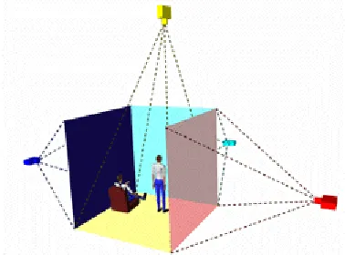
1.4.2 CAVETM
The CAVETM (Cave Automatic Virtual Environment) was developed at the University of Illinois at Chicago and provides the illusion of immersion by projecting stereo images on the walls and floor of a room-sized cube. Several persons wearing lightweight stereo glasses can enter and walk freely inside the CAVETM. A head tracking system continuously adjusts the stereo projection to the current position of the leading viewer. A CAVETM system schematic is shown in Figure 1.2.
1.4.3 Data Gloves
Data gloves provide feedback to the computer regarding the motion of the digits on a left or right hand. The data gloves can be tracked, and this provides the location of the hand in addition to the position of all digits. A data glove, shown in Figure 1.3, allows for interactions with the virtual world as illustrated in Figure 1.4.
Figure 1.3: Data Gloves Figure 1.4: Application of Data Gloves
1.4.4 Pinch Gloves
developers and users of immersive applications to use hand interaction to work within the virtual environment.
Such actions may be selecting objects, opening and closing doors, moving objects, etc., much as hands are used in real world everyday activities. [Fakespace, 1997]. Figure 1.5 provides a photograph of the pinch glove system
Figure 1.5: Pinch Glove System
1.4.5 Joystick, Wand, or Flightstick
Figure 1.6: Flightstick
1.4.6 Shared Virtual Environments
Figure 1.7: Networked Virtual Environments
Today, the term 'Virtual Reality' is also used for applications that are not fully immersive. The boundaries are becoming blurred, but all variations of VR will be important in the future. This includes mouse-controlled navigation through a three-dimensional environment on a graphics monitor, stereo viewing from the monitor via stereo glasses, stereo projection systems, and others. Apple's QuickTime VR, for example, uses photographs for the modeling of 3D worlds and provides pseudo look-around and walk-trough capabilities on a graphics monitor. [Beier, 2004]
1.4.7 ImmersaDesk
with stereo sound. The ImmersaDesk cabinet is on wheels and folds up and fits through doors. [Czernuszenko et al. 1997]. Figure 1.8 shows the Immersadesk system.
Figure 1.8: The Immersadesk System
The projector is located in the lower section and a pop-up mirror folds the optics. The screen can rotate to the transportation position, where it is enclosed in the ImmersaDesk body, allowing the system to have a footprint of 34 inch depth by 73 inch width.
Only one graphics pipe is needed for the ImmersaDesk, which allows the use of a less expensive mid-range workstation. The decision to tilt the screen 45 degrees came from experience with the CAVETM. In the CAVETM, users usually look at images that are displayed on the walls. This might suggest that the CAVETM floor is not important. However, if the floor is not used, a significant part of the VR experience is lost. This idea resulted in the design of the ImmersaDesk to support looking down, as well as forward [Czernuszenko et al. 1997].
uniformly bright, one has to choose a low gain screen. This screen is made of a clear plexiglass with sprayed on backcoating [Czernuszenko et al. 1997].
All parts of the ImmersaDesk cabinet are made of wood or stainless steel, so as to minimize interference with the electromagnetic tracking system. The ImmersaDesk uses the same CAVETM library software as is used in the CAVE, to generate accurate perspective projection, and to read tracker and input devices. Therefore, applications developed for the CAVE can be run on the ImmersaDesk, and vice versa, without any code changes [Czernuszenko et al. 1997].
1.4.8
CrystalEyesFigure 1.9: Crystal Eye Glasses
2.
GESTURAL INTERFACE
2.1 What is a Gesture?
Perceptual, cognitive, and usability evaluations have motivated the use of gestures as an interaction technique in virtual environments for their potential to increase speed and accuracy in task performance as well as improve usability. A gesture may be defined as a physical movement of the hands, arms, face, and body with the intent to convey information. Gesture recognition, then, consists not only of the tracking of human movement, but also the interpretation of that movement as semantically meaningful commands. Interpretation can vary in resolution and encompass a range of large and small scale motions, including tracking in which the subject is viewed as a single object, tracking of the subject as an articulated kinematics structure, and tracking of small-scale movements such as facial expression and hand gestures.
Gestures are identified by their function, their linguisticity, and their role in communication. Gestures are grouped according to function as semiotic, ergotic and epistemic [Cadoz, 1994].
Semiotic gestures convey meaningful information by facilitating communication. Semiotic gestures are frequently derived from shared cultural experience. Waving good-bye or giving someone the “finger” are examples of semiotic gestures in the USA. Ergotic gestures include manipulations of the physical environment, and are frequently related to the notion of work. The act of putting an object onto a shelf is ergotic gesture. Epistemic gestures involve the process of discovering the environment through tactile experiences. Judging the weight of an object by holding it in one hand or is an example of epistemic gesture.
Gestures are also classified according to their linguisticity. This classification forms a continuum
sign language towards decreasing autonomy are emblematic, pantomime, and language-like gestures. Emblematic gestures are symbolic gestures which, as noted above, are frequently culturally-specific representations. Pantomime gestures accompany speech by depicting objects or actions. For instance, a pantomime occurs when a person describes the size of a fish. Language-like gestures are those gestures which are fully integrated into speech, often replacing a particular word or phrase. These frequently may be full-body gestures including posture and facial expressions. Gesticulations, the least autonomous of the semiotic gestures, include spontaneous and idiosyncratic movements of the body that accompany speech. Gesticulations are seldom culturally defined and almost never occur in the absence of speech.
Semiotic gestures are further classified by their role in communication as iconic, metaphoric,
deictic, and beat-like [McNeill, 1992]. Iconic gestures are representative of an action, object or event, while metaphoric gestures depict a common metaphor rather than depicting the event or object directly. Pointing gestures which are used to indicate people, objects, or directions are deictic gestures. Beat-like gestures are small, emphatic gestures generally performed with the hand or the head.
Another method of classifying gesture makes use of four dichotomies: act-symbol, opacity-transparency, autonomous semiotic-multisemiotic, and centrifugal-centripetal [Nespoulous, 1986]. Examination of these dichotomies provides insight into the range of communication and command capabilities of gesture, as well as some of the issues related to the use of gesture-based interaction techniques.
emotion, such as giving someone “the finger” or a “thumbs-up” signal. Action gestures are particularly applicable to use in gesture-based interaction techniques for commands which parallel a real world task. Symbolic gesture sets may also be effectively implemented when their recognition rate is high across the user population.
The opacity-transparency dichotomy expresses that gestures may not be easily accessible to all individuals, and that many gestures lack universality. A higher rate of recognition across individuals and cultures is associated with transparency. While the notion of cross-cultural gestures seems plausible, few if any known body motions or gestures have been identified to have the same meaning in all societies [Birdwhistell, 1970]. American Sign Language (ASL) is an example of an opaque gesture set. Though many signs are reminiscent of the words or concepts they represent, an observer unfamiliar with the language would be unable to interpret a signed communication. As a result, the use of sign language gestures in an interaction technique would require advanced training and make it difficult for novice users to interact with the application.
Finally, the centrifugal-centripetal dichotomy describes a gesture’s direction of intent. Centrifugal gestures are directed towards specific objects or people, whereas centripetal gestures are not. A pointing gesture to indicate which object is being discussed would be centrifugal in nature, whereas a gesture using the hands to indicate relative size or location would be centripetal.
2.2 How to use gestures?
Incorporating hand gestures into an existing GUI permits exploration of how it meshes with current interface technology and how it compares to current interface devices. Using this knowledge one can determine if future systems can benefit from using gesture, and if so, what changes must be made to accommodate gesture.
While the interface envisioned here looks in many ways similar to standard GUIs of today, this thesis does not attempt to argue that simply using gesture as a direct mouse replacement in a current GUI gives any real advantages. Indeed, many aspects of current interfaces are tuned to complement specifically the capabilities of the mouse and keyboard, and as such are not well suited for gesture. It is argued, however, that in the context of an appropriately designed interface, gesture can offer real advantages as an interface modality.
environments. Within an individual cultural group, these gestures may also be more consistent in their performance, thus improving tracking and recognition.
2.3Usability and Ease of Use of Gestures
Gesture-based interaction techniques have found both support and criticism in the area of usability. Gestures have been offered as a means of “natural interaction,” for their properties of direct interaction, their flexibility, and their reality of experience. However, gestures have also been described as imprecise, non-ergonomic, and not self-revealing.
For new VR users, knowledge of how to manipulate objects or travel through an immersive environment, or even the knowledge that such tasks might be available, is often not self-revealing. VR applications are primarily designed with an expert user in mind, and new applications tend to require training on the interaction techniques even for those familiar with the technology. Information about how to interact with the VE is seldom “stored in the world” [Norman, 2002], with the physical devices giving clues to their use. Gesture recognition overcomes this problem by making use of emblematic, pantomime and natural ergotic gestures to represent common actions or semantic expressions [Kendon, 1972]. Examples of these might include holding the hand up palm out for “stop” or both hands out in front with fists clenched to mimic the act of riding a bicycle. These are symbolic gestures which carry clear and familiar, although, sometimes culturally specific meaning, and can be associated with VE tasks to provide both new and experienced users with a set of intuitive commands.
As gesture recognition techniques improve, gesture has the ability to be a highly flexible means of interaction. Instead of confining the user to an arbitrary, rigidly defined gesture set, gesture interaction techniques can adapt to changing user characteristics, including changes due to fatigue, level of experience or disability [Williams et al, 1990]. Allowing for flexibility in input styles would ensure a broader user base and could help reduce repetitive strain and overexertion. Improvements in recognition could also help combat complaints regarding the lack of precision in gesture-based interactions. While some variability in gesture systems may be due to limited precision of the tracking equipment itself [Mine et al, 1997], blame may also lie with the developer. Gestures may be tracked at the level of the body, the hand and arm, the hand and fingers, or the head and face [Turk, 2002]. The choice of resolution imposes constraints on the precision and repeatability of the gesture commands. For example, the average user on a full-body scale cannot replicate the fine motor control and accurate positioning that is possible with the fingers. In his development of a hand-based gesture system, Wexelblat [1995] quantified movements in more “expressive” joints of the hand (e.g. the index finger) as more significant to determinations of gesture than the movements of less expressive joints (e.g. the pinkie). Thus, movements in the pinky must be larger to be recognized by the system than what would be required of the higher-precision index finger. At the implementation level, Mulder [1996] argued that lower precision and computational power was required for semiotic gestures than for ergotic motions. The latter requires the accurate detection of more complex, continuously changing motions through dynamic gesture recognition, while the former could be tracked by recognizing a discrete number of postures or positions through static gesture recognition.
and monitoring the user’s motions. Thus, gestures can be evaluated by the system whether or not they were intended for interpretation. This constant monitoring may limit the user’s ability to communicate via gesture to other devices or with other people in the environment, if gestures are not well selected and defined.
Body-centered and arm and hand-based gestures have the potential to suffer from additional precision degradation due to ergonomic factors. Care must be taken to design gestures that do not require awkward posturing, repetitive motion, and excessive repetition. As gestures do not introduce external forces on the body, they could be described as ergonomically superior interaction methods; however, the lack of registration with a physical surface provides no external frame of reference, and no means to steady the body. Under such conditions, gesture has the potential to cause tension and fatigue. Increased arm fatigue due to tension or posturing has been found to degrade performance [Baudel et al., 1993]. To reduce fatigue, gesture commands must minimize effort and be quick and easy to execute. User discomfort may also occur in cases in which users must wear a glove or other tracking devices on the body and be linked to the system via wires. Improvements in computer vision techniques continue to alleviate these problems by providing effective, wireless solutions.
correlated with reality of experience, including successfully supported action in the virtual environment [Slater, 2004; Zahoric et al., 1998].
2.4 The Role of Non-Symbolic Gestures
While the selection of intuitive gestures favors learning and ease of use, it reinforces the trade-off between ease and expressiveness [Martin, 1989]. Complex and non-symbolic gestures may be difficult to learn and retain, but have the potential to provide a greater range of expression and control than do emblematic or pantomime gestures [Baudel et al., 1993]. Developing gestures for command and control tasks such as save, load, and change color commands may be particularly challenging, as these have no consistent physical manifestation. Wexelblat [1995] noted that poorly chosen mapping of gesture input to commands might provide minimal functional gain over a button or key-based system. Instead of enabling ease of use, such techniques may induce cognitive load due to requirements for the user to memorize the gesture set. In the desktop domain, evidence points toward a gain in efficiency and control once gestures are learned. Through the use of shortcut key commands, for example, an expert user can easily outperform a less experienced typist who must move back and forth from mouse to keyboard input. Though initially unintuitive, these command sets provide a physical mnemonic and reduced motion set, which improves accuracy and performance.
Great success has been shown in the application of gestures to desktop interfaces, with the most notable example being the TouchStream keyboard and iGesture pad by FingerWorks [FingerWorks, 2002]. These systems use a technology called MultiTouch to sense and interpret
surface, eliminating hand movements to the mouse or the use of hotkey sequences. Finger combinations and a direction of motion define gestures. For example, the user can open a new file by touching the keyboard with the thumb and first three fingers and rotating on the pad in a counterclockwise direction in a manner similar to opening a jar. While some gestures are relatively symbolic, others are more arbitrary. To copy a selected item, for example, the user touches the keyboard with the thumb and middle finger. To paste copied text, the user touches the keyboard with the same finger combination and then spreads the fingers on the pad.
TouchStream’s gesture set had been designed to be fairly intuitive, but it still requires a modest training time. FingerWorks does not recommend the TouchStream keyboard for older users who may have limited hand agility or users unwilling to spend time “relearning” how to type. With constant use, touch typists are expected to reach moderate speeds of 30-40 words per minute within a few days, with a return to full proficiency taking 3-4 weeks of practice [FingerWorks, 2002]. Average typing speed is 50-60 words per minute while accomplished typists reach speeds of 60-70 words per minute.
2.5 Task-Based Evaluation of Gesture Interactions
Gesture-based methods are not the most effective interaction scheme in all instances, and gesture recognition should not be used purely for its own sake. It cannot replace the precision of some interaction devices, and may be a less effective paradigm in some cases than more standard input techniques. However, gesture-based approaches do have unique advantages over other input technologies.
process of empirically assessing interaction techniques for virtual environments in a generic context through the description of taxonomy of interactions for the tasks being evaluated [Bowman & Johnson, 2001; Bowman, Johnson, & Hodges, 1999; Poupyrev, et al, 1997]. In Bowman Johnson, and Hodges [2001], a set of universal interaction tasks for virtual environments are defined, including selection, manipulation, release and travel. These tasks are subsequently broken down into sets of separable subtasks. For example, the manipulation of an object might be composed of three subtasks: specifying the position of the object, specifying the orientation of the object, and providing feedback to the user. These subtasks may then be broken down into finer-grained descriptions including the type of interaction method implemented. Thus, the process of specifying the new location of the object in a manipulation task may be implemented with xyz sliders or by indicating a point in the 3D space with a wand or glove device. An interaction technique is made up of one technique component from each of the lowest-level subtasks.
2.6 Gesture in Selection
The task of selection encompasses the specification of an object or set of objects, most frequently for the purposes of manipulation or as the referent of a command. Selection is a frequently occurring task, and thus should be implemented to maximize efficiency. Gesture is an ideal interaction technique for selection tasks as it may be implemented in a way that closely mimics real-world interactions. Gesture-based selection is most frequently implemented via a virtual hand metaphor, pointing or arm extension, or through occlusion or framing of an object.
techniques have been developed to extend the user’s grip to remote locations in the VE. These arm extension techniques may be used to supplement gesture-based selection controls. A common example of an arm-extension implementation is the Go-Go technique [Poupyrev, et al. 1996], in which nonlinear mapping of the user’s hand position is applied when the physical hand exceeds a radius of proximity to the body. Thus, when the hand operates outside that radius, it may select distant objects using the same techniques that would be used to interact with objects closer to the body.
Ray-casting techniques make use of deictic or pointing gestures. A ray directed by the user’s hand and arm posture is used to indicate referent objects within the scene. Ray-casting saw its first application in Bolt’s “Put-That-There” interface (1980), in which gesture was used to disambiguate pronouns and allow for the specification of unknown or remote objects in the scene. Bowman and Hodges [1999] assert that ray-casting performance is more efficient than arm extension over a range of object distances, object sizes, and object densities. Their belief is that this difference is due to their reduction of Ray-casting to a 2D task through the elimination of changes in the roll of the wrist or hand. Ray-casting may be implemented as either a 2 or 3 degree-of-freedom task.
2.7 Gesture in Manipulation
Manipulation is the second task classification in the taxonomy of VE interaction tasks, and most frequently follows selection. Manipulation refers to the user’s ability to change the properties or positions of objects in the VE. VE manipulation may include changes to the orientation or scale of objects as well as changes to other attributes such as shape, color and texture. It should be noted that command and system control tasks such as the interaction with menus or control panels do not fall under the manipulation heading, instead being classified as selection techniques.
Gesture-based manipulation tasks may take the form of direct object manipulation, indirect object manipulation, relative manipulation, and direct viewpoint manipulation. Direct object manipulation is an extension of the virtual hand metaphor for manipulation, and is a simple and intuitive means of controlling the position and orientation of a selected object. In these cases, the selected object is attached to the virtual hand and the actions of the physical hand are used to transform the object [Poupyrev et al., 1996]. Kinematic constraints limit the number of positions a user can achieve, however, so care must be taken to implement an approach that allows the user to quickly deselect the object and cease manipulation once a constraint is reached. Direct manipulation has been shown to perform more efficiently and provide a higher level of user satisfaction than techniques that involve tool-use or indirect manipulation such as Ray-casting [Bowman & Hodges, 1999]. The combination of Ray-casting for selection and direct manipulation for object transformations is the basis of the HOMER technique [Bowman & Hodges, 1997] and Sticky Finger [Pierce et al, 1997].
interactive applications. The use of two hands increases the flexibility and expressiveness of the available command set by increasing the number of possible commands and physical mnemonics. Remote manipulation of objects becomes simple and intuitive with relative positional commands. The non-dominate hand may be used to provide a frame of reference, while the dominant hand is used to specify more precise relative transformations.
While manipulation is most frequently applied to objects in the scene, it may also be used to update view orientation, if this is not specified via the orientation of the user’s head. Direct object manipulation operates via a “camera in hand” or “scene in hand” metaphor in which the selected object remains fixed in the environment and the user manipulates the viewpoint using gesture. In general, this approach has shown to be less effective than viewpoint updates specified via head orientation as it limits the user’s understanding the spatial structure of the complete environment [Chance et al.1998]. Manipulations of this sort are commonly implemented and highly effective in design, prototyping and simulation applications.
2.8 Gesture in Travel
Gesture input is well suited for control of direct steering and target-based travel techniques. The former can be implemented in a variety of ways, including gestures which mimic steering of bicycle handlebars or the wheel of a car or simple mapping of the direction of travel to the posture of the user’s arm or hand. Steering techniques allow the user to look at objects of interest while moving, and take advantage of body-centered cues for direction. Target-based travel techniques provide the simplest metaphor for navigation, in which the user specifies a target in the environment to which the application should initiate travel. This method assumes that the goal location is known in advance and is visible by the user, though the technique may be implemented in a general manner that operates similar to steering techniques in the absence of a target. While target-based techniques have been found to be easily understood by novice users, steering techniques afford a higher degree of control and provide greater levels of spatial orientation [Bowman et al. 1999].
Navigation via relative motion of the body may be implemented in ways similar to relative manipulation and viewpoint techniques. Two-handed interactions may be utilized in flying or driving paradigms, in which the positions of the hands relative to one another control not only the direction of travel but also affect speed control via hand separation. Mine et al., [1997] recommended the use of head and hand posture to enable users to quickly switch between close, local views and more global distant views using a technique called “head-butt zoom.”
translation and rotation to maintain the user’s focus on the display. Locomotion interfaces are frequently used in military simulation and training applications. It has been found that locomotion calibrates distance judgments and may contribute to an increased sense of presence and task transfer [Hollerbach, 2002]. Locomotion interfaces may be used to simulate walking, running and climbing activities and may be triggered via gestural knee actions, classifications based on head bobbing, and detection of hand gestures to indicate ascending or descending a ladder [Slater et al, 1995]. The combination of gesture and mechanical locomotion solutions shows promise in aiding in the development of advanced interaction techniques for training and simulation.
2.9 Gesture in Traditional User Interfaces
Relatively little work has been attempted to use gesture in a traditional user interface. Of that which has been done, the most common approach is to use gesture as a direct mouse replacement. This has most often been done using indirect positioning. In other words the user moves their hand within some control space to move the cursor about the screen in an analogous fashion, rather than pointing directly at the screen to indicate exactly where they want the cursor to go. Both absolute positioning, where the location of the hand or an extended finger within the control space is mapped directly to a screen location, and relative positioning, as is done with a mouse, has been used. Typically some action, such as a change in pose or a key press by the other hand is used to simulate a mouse click.
Nesi and Bimbo [1995] used two cameras to position the mouse in 3-space. The hand is observed against a black background in a workspace, presumably to the side of the keyboard. The motion of the hand is smoothed using a predictive polynomial filter. To take the place of mouse buttons, three hand poses are used: palm down with the fingers extended and together, rotated from that 90 degrees so the palm faces sideways and the thumb is up, and palm down with the fingers curled in a fist. The poses are differentiated by taking the ratio of the sides of the bounding box of the hand when viewed from above.
having users fill out on-screen forms, using pointing to select the field to type in. Some work has been directed at designing a workstation to make greater use of gesture.
Maggioni [1995] describes several additions to a conventional workstation that allows it to use both hand gestures and head movements. One camera images the user's face, another looks down on a region to the side of the keyboard to image the user's hand. When the hand is on the desk, its position is used to position the cursor like a conventional mouse. When it rises off the desk it enters a 3D mode where movement in the center of the imaged volume positions a 3D cursor. When the hand nears the edge of the control volume it moves the observer's viewpoint of the virtual space. Maggioni describes several hand poses that can be differentiated, but does not suggest how they might be used.