Strojniški vestnik - Journal of Mechanical Engineering 53(2007)5, 285-296 UDK - UDC 681.586:007.52
Izvirni znanstveni članek - Original scientific paper (1.01)
Položajno zaznavalo za premični robot
Position Sensor for a Mobile Robot
Rajko Mahkovic
(Fakulteta za računalništvo in informatiko, Ljubljana)
V prispevku predstavljamo izvirno položajno zaznavalo za premični robot. Zaznavalo je namenjeno natančnemu merjenju položaja premičnega robota. Sestavljajo ga merilno kolesce, absolutni zapisovalnik
matematično izpeljavo razmerja med spreminjanjem smeri merilnega kolesca, njegove prevožene razdalje in spremembo robotovega položaja v kartezičnem koordinatnem sistemu. Obravnava je razdeljena na dve stanji: ko je merilno kolesce usklajeno s smerjo premikanja robota in ko ni usklajeno. Predstavljeni so eksperimentalni rezultati na dveh vrstah poti premičnega robota: vožnji v obliki osmice in vožnji po dolgem in ozkem hodniku. Rezultati kažejo, da je predlagano položajno zaznavalo tako natančno, kakor klasična rešitev z dvema merilnima kolescema, nameščenima na vsako stran od pogonskega kolesa. Položajna napaka zaznavala na omenjenih poteh, dolgih 20 m, v obliki osmice, in 120 m v primeru hodnika, znaša manj ko 0,4 odstotka prevožene poti. Položajnemu zaznavalu moramo določiti vrednosti štirih parametrov: obseg merilnega kolesca, ničelni kot zasuka, odmaknjenost merilnega kolesca in oddaljenost mesta namestitve zaznavala od referenčne točke premičnega robota.
O 2007 Strojniški vestnik. Vse pravice pridržane.
(Ključne besede: mobilni robot, položajna zaznavala, merilni sistemi, odometrija)
A new position sensor is presented, designed fo r accurate measurements o f the relative position o f a mobile robot. It consists o f a measurement wheel, an absolute optical encoder fo r measurements o f the robot's orientation and a relative encoder fo r measurements o f the distance covered by the robot. A mathematical description o f the relation between the measurement wheel's orientation alteration, the distance that has been covered and the change o f the robots' position in the Cartesian coordinate system is given. The discussion is divided into two situations: the first, in which the measurement wheel is aligned with the current robot's path, and the second, in which it is not. In the experiments the robot was sent to drive along a figure-of-eight-shaped path and along a long and narrow corridor. The results prove that the proposed sensor is as accurate as the classical solution o f two additional measurement wheels, mounted on each side o f the driving wheels. The error in the position remains below 0.4% o f the travelled path fo r both types ofpaths. The position sensor needs to be calibrdted with the values o f four parameters: the circumference o f the measurement wheel, the initial offset (the angle o f the absolute encoder corresponding to the zero orientation o f the robot), the eccentricity o f the measurement wheel, and the distance between the sensor and the reference point o f the robot.
© 2007 Journal o f Mechanical Engineering. All rights reserved.
(Keywords: mobile robots, position sensors, measurement systems, odometry)
I : *r
0 UVOD
Odometrične merilne metode, merilne metode, ki temeljijo na meijenju prevožene poti, so, kakor kaže, še vedno dovolj natančno in ceneno sredstvo za določanje trenutnega položaja premičnega robota. Vrsta metod [1], ki določajo absolutno lego robota, sicer zagotavlja poznavanje njegove lege, vendar le
0 INTRODUCTION
na posebnih mestih delovnega prostora. Navadno m oram o za to poseči v delovni prostor robota, z nameščanjem, recimo, nalepk, dejavnih oddajnikov, ali pa se zanesti na razpoznavanje njegovih krajevnih značilnosti (stene, vrata, predmeti itn.) Zelo primerne so, na prim er, Voronoijeve točke posplošenega istoimenovanega diagrama delovnega prostora [6]: ne samo, da dajejo rekalibracijo robotove lege, osvežimo lahko tudi njegovo usmeritev. Ob tem, da je gibanje v delovnem prostoru načelom a najbolj varno, saj je Voronoijev diagram krčenje praznega p ro sto ra , zato je ro b o t pri p rem ik an ju vzdolž Voronoijevega diagrama najbolj oddaljen od ovir, kot je to le mogoče.
Pri delu z notranjimi premičnimi roboti imamo o b ičajn o na voljo njihovo absolutno lego le v posam eznih točkah prostora, za prem ik od ene absolutne lege do druge pa se odločimo za neko relativno merilno metodo. Odometrija se v ta namen izkaže kot primerna izbira, njena najbolj natančna izvedba, uporaba dodatnih merilnih kolesc, pa kot poceni in učinkovita relativna merilna metoda ([4] in [5]). Taka merilna kolesca se običajno namesti na levo in desno stran pogonskih koles premičnega robota.
Ker se je pokazalo, da je namestitev takih merilnih kolesc tako konstrukcijsko, kakor gibalno (premični robot se ne more premikati vzvratno) precej om ejujoče, smo želeli poiskati tako konstrukcijo m erilnega kolesca, ki za robota ne bi bila tako omejujoča, ne bi bila tako odvisna od razlik v izdelavi merilnih kolesc, a bi še vedno ohranila vse prednosti odometrije. Razlika v, na primer, obsegu merilnih kolesc se tako na koncu izraža kot zasuk v usmeritvi robota; ta poleg tega lahko nastane dodatno tudi zaradi daljše prevožene poti enega od kolesc, ker se pač kolesca kotalita po različno ravnih podlagah.
1 POLOŽAJNO ZAZNAVALO
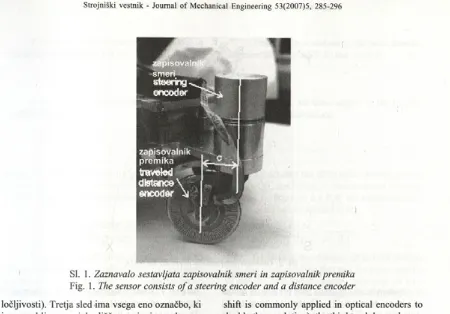
Položajno zaznavalo na sliki 1 sestavljata relativni optični enkoder za merjenje prevožene poti, zapis prem ika, in absolutni optični zapisovalnik za m erjenje trenutne robotove usmeritve, zapisovalnik sm eri. Z asnova zapisovalnika poti ni običajna: nam esto osvetlitve skozi masko, ki pri kolesu pač ni iz v e d ljiv a , sm o u p o rab ili odboj od m aske, nalepljene na merilno kolesce. Maska, izjedkana iz plošče za izdelavo električnih tiskanih vezij, ima tri sledi: zunanji dve s po 180 zarezami na zasuk sta fazno prem aknjeni za 90° (tak fazni prem ik mask je pri zapisovalnikih običajen način za podvojitev
positions o f the working space. Nevertheless, some kind o f intervention in the working space is neces sary for them to be applied, e.g., the placement o f labels, active transmitters, or recognition o f the lo cal features o f the working space (walls, doors, vari ous objects, etc.). For example, Voronoi points o f the generalized Voronoi diagram could serve for this purpose [6]: not only the robot’s position, but also its orientation could be recalibrated. In addition to this, the m otion o f the robot is safer, since the Voronoi diagram is a retraction o f the free space, which guarantees that the robot is as far from obsta cles as possible.
A n indoor mobile robot is supplied, as al ready mentioned, with its absolute position only at specific places o f the working space; to move among these places it needs to rely on a kind o f relative measurement method. Odometry has proved to be a quite effective choice, especially in its m ost accu rate implementation, with the use o f additional meas urement wheels ([4] and [5]). Such m easurement wheels are normally placed to the right- and left- hand sides o f the robot’s driving wheels.
Unfortunately, such wheels turn out to be awkward to mount, and they restrict the movements o f the robot. Therefore, it was our intention to find such a construction o f an additional measurement wheel that would not depend so strongly on the differences between both wheels (which actually in troduce positional errors), yet it would still preserve all the advantages o f odometry. The difference, for instance, in wheels’ circumferences manifests itself as an additional turn in the orientation o f the robot; the same effect could be produced by the difference in the lengths o f the paths the measurement wheels travel along, caused by an uneven floor.
1 POSITION SENSOR
Sl. 1. Zaznavalo sestavljata zapisovalnik smeri in zapisovalnik premika
Fig. 1. The sensor consists o f a steering encoder and a distance encoder
ločljivosti). Tretja sled ima vsega eno označbo, ki je uporabljena za izhodišče m erjenja po krogu, referenčni sunek.
Merilno kolesce se, kakršen koli že je njegov začetni zasuk, med vožnjo postopno poravna s smetjo vožnje; glede na os zapisovalnika smeri je namreč n am eščen o izsred n o . M ed v o žn jo se torej iz prevožene razdalje in trenutne smeri izračunava premik robota v kartezičnem koordinatnem sistemu.
M a te m a tič n i op is m e riln e g a sistem a podajamo v nadaljevanju. Izkaže se, da moramo obravnavo pravzaprav razdeliti na dva primera: prvič, d a je merilno kolesce v smeri vožnje poravnano, in drugič, da merilno kolesce v smeri vožnje robota še ni poravnano.
V nadaljevanju bomo obravnavali najprej zahtevnejši drugi primer, pri katerem torej merilno kolesce ni poravnano s smetjo vožnje; predvidevamo, da nam bo obravnava tega primera ponudila zadosten vpogled tudi za obravnavo primera, pri katerem je merilno kolesce poravnano.
shift is commonly applied in optical encoders to double the resolution); the third track has only one line, used to m ark the position of each full turn o f the wheel, the reference pulse.
The measurement wheel, whatever its initial orientation, aligns gradually with the direction o f the path; because it is mounted eccentrically in terms o f the axis o f the orientation encoder. During the movements, the traversed distance and the current orientation determine the change o f the position in the Cartesian coordinate system.
A mathematical description of the measuring system is given below. It turns out that the discussion should be divided into two situations: the first, in which the measurement wheel is aligned with the orientation with the robot, and the second, in which it is not.
The following discussion will first focus on the second, more demanding situation, in which the measurement wheel is not aligned with the orienta tion o f the robot; we believe this case will also give us sufficient insight into the former.
2 NEPORAVNANO MERILNO KOLESCE (NMK)
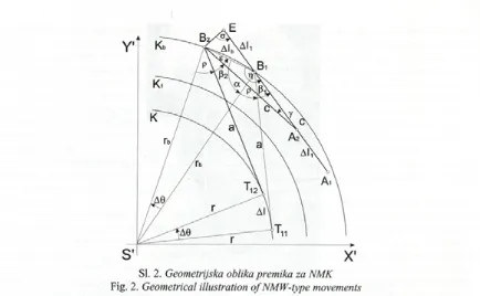
Predpostavim o, da se robot giblje vzdolž krožnega dela poti. Referenčno točko robota bomo označili s T , središčno točko zapisovalnika smeri z Bx, dotikališče m erilnega kolesca s tlem i Ax; pri
2 NON-ALIGNED MEASUREMENT WHEEL (NMW)
Let us suppose the mobile robot moves along a circular arc. We denote the reference point o f the robot by 7 j , the centre o f the steering encoder by B ,
Sl. 2. Geometrijska oblika premika za NMK
Fig. 2. Geometrical illustration ofNMW-type movements
Xoznačuje indeks položaja pred prem ikom robota (1) in po prem iku (2). D olžini \ A ß x\ in \A2B21 pom enita prem ik c, označen na sliki 1, a pa razdaljo m ed referenčno točko robota in osjo kodim ika smeri (dolžini \TUB^\in \Tvß 2\ ).
K o se, na prim er, referenčna točka robota p rem ak n e po krožnem loku z uk riv ljen o stjo K iz
Tu v 7 j2, se središče enkoderja sm eri prem akne po k ro žn em loku z u k riv ljen o stjo Kb iz B t v B2,
d o tik a lišč e m eriln eg a kolesca pa iz A v A r Pri tem referen čn a točka robota opravi prem ik po krožnem loku Al, sm er ozirom a usm eritev robota pa se sprem eni za A 0 . Če bi bilo nadalje, m erilno k o lesce že po rav n an o glede na sm er vožnje, bi
A i in A 2 ležali na krožnem loku s p o lm erom K r
P red p o stav im o , d a j e prem ik dovolj m ajhen, da lahko vzam em o, da leži k ar na d aljici AtB, .
P re m ik A/, je p r i te m ra z d a lja , iz m e rje n a z kodim ikom poti. (Vidimo, da sta Al in Al krožna lo k a , m e d te m k o j e A/ d a ljic a .) T o č k o E
d o lo čim o tako, da dobim o enakokraki trik o tn ik
AA 2B 2E.
floor by Ax, where x denotes the index o f the position before the movement (1) and after the movement (2). The straight lines |A ]BI | and \AßJ are the eccentricity c
from Figure 1, whereas a is the distance between the robot’s reference point and the centre o f the steering encoder (straight lines \Ti}B t\ and \ T ß 2\ ).
As, for example, the robot’s reference point moves along a circular arc with the curvature K from 7j | to Zj2,the centre of the steering encoder moves along the circular arc with the curvature K, from B, to IE, whereas the con- tact point of the measurement wheel moves from ri ( to A2.
During this movement, the robot’s reference point moves along the arc Al, while the change in the orientation of the robot amounts to A©. Furthermore, if the measurement wheel was aligned with the path of the movement, the points A ! and A2 would he on the circular arc with curva ture Aj. Let us presume that the movement is small enough to assume thatri2 lies on the straight line A ß ,. The length A/] is the distance measured by the distance encoder. (Note that Alh and Al are circular arcs, whereas A/ps a straight line.) Point E is determined in such a way that an isosceles triangle, A A ß ß , is formed.
2.1 Izračun spremembe robotove usmeritve 2.1 Calculation of the change In the robot’s orientation
Iz enakih pravokotnih trikotnikov AS* T B
in A S 'T ß lahko izračunamo kot p:
We calculate the angle p from the observa tio n o f tw o rectan g u lar triangles A S T , ,5 , and
A S ß ß
K ota a in a izračunam o iz enakokrakih trikotnikov AS,B lB2 in AA ß ß :
Next, angles « a n d erare calculated from the isosceles triangles AS,B ]B2 and AA2B2E:
a = ( n -A 0 )/2
a = { ji- y ) /2
S tem pa že lahko izračunamo vse tri kote v A nd now, all three angles in the triangle
trikotniku AA ß 2B x: AA2B2B] can be determined:
s = n / 2 - A 0 / 2 - p - ß 2
r] = 7 i/2 -A ® /2 + p + ß l y = A® + Aß
kjer je A/?razlika med končnim kotom ß2 in začetnim where A ß denotes the difference between the an-kotom ß y Po določitvi še vseh treh stranic trikotnika gles after, ß2, and before, ß x, the movement. After the
AA2B2B X, lahko na njem uporabimo sinusni izrek: sides o f the triangle AA1B2B] are established, the
sine theorem can be applied to it:
2rb sin(AQ/2) c _ c -A /,
sin(A© +A/?) s i n ( ^ / 2 - A 0 / 2 + p + ß ß sin(rr/ 2 - A© /2 - p - ß 2) (2).
Iz razmerja prvih dveh ulomkov že lahko dobim o diferencialno enačbo, tako da pošljem o sprem em bi A ß in A© proti nič. Z avedati pa se moramo, da če hkrati pošljemo A ß in A 0 proti nič, bodo vse izpeljane enačbe veljale le v primeru, če je zapisovalnik smeri neporavnan v sm eri vožnje. Dobimo naslednjo diferencialno enačbo:
By limiting the changes A ß and A© towards zero, the relation o f the first two fractions supplies us with the differential equation. However, we have to keep in m ind that sending both differences to zero simultaneously implies that all the derived equa tions will hold only to the NMW situation. The fol lowing equation is obtained:
rbd&
iz katere izrazimo d®:
dQ + d ß cos (ß + p)
d®--rb cos(/? + p)d® = cd® + cdß
from which d® can be determined:
rbcos(ß + p ) - c d ß
(3),
(4).
Po integraciji leve strani enačbe od 0 do A 0 in desne strani od ß do ß 2 ter zapisu ukrivljenosti namesto obratne vrednosti polmera krožnega loka
K b = 1 /rb, dobimo enačbo spremembe usmeritve robota
After the integration o f the left-hand side from 0 to A© and the right-hand side from /?, to ßv
and the use o f the curvature K.b = 1/r. is introduced,b the equation that gives the change o f the robot’s orientation can be written as:
A© : kjer sta
m <£-(/?,) = (1+cK4) tan
where
(sx
2 and
®+(Ä) = (l + c*,)tan| ^ ^ j + Vl
~cKb
2.2 Izračun prevožene poti merilnega kolesca 2.2 Calculation of the length measured by the meas urement wheel
Prevožena pot merilnega kolesca Al t je sicer podatek, ki ga preberemo iz zapisovalnika premika,
how-toda potrebujemo njegovo povezavo s preostalimi spremenlj ivkami v merilnem sistemu. Postopek izračuna je podoben zgornjemu izračunu spremembe robotove usmeritve, le da tokrat uporabimo trikotnik A R R E .
Najprej izračunamo vse trikotnikove notranje kote:
a = (A0
ZBXB2E = a - s
ZB2BtE = n- tj = n
nato pa še dolžine njegovih stranic. Tudi v tem trikotniku uporabimo sinusni izrek in dobimo:
ever, it should be related to the other system v a ri ables. The procedure we will use is somewhat sim i lar to the one above, except that triangle AB XB 2E is observed this time.
All three angles are determined first:
■Aß) 12
ß 2+ p - A ß / 2
2 - ß - p + A®/2
and all three sides. A fter that the sine theorem is applied for this triangle too, obtaining:
2c sin((AQ + Aß) / 2) _ A/, _ 2rh sin(A0 / 2) sin O / 2- / ? , - P + AQI2) sin(/?2 + p - A ß ! 2 ) ~ sin(^ / 2 - (A 0 + Aß) / 2)
Iz razm erja prvih dveh ulom kov dobim o diferencialno enačbo, če pošljemo spremembi A ß in A© proti nič. Spet pa se moramo zavedati, da vse nadaljnje enačbe veljajo le v prim em , da merilno kolesce ni poravnano:
c(d@ + d ß ) dl,
cos(ß + p) sin(ß + p )
N a m esto d® vstavimo diferencialno enačbo <=> c
From the relation between the first tw o fra c tions another differential equation is obtained, lim it ing the differences A ß and A© to zero. Again, the equations hold for the NM W case:
sin (ß + p)
cos(ß + p)(d® + d ß ) = dli
(4):
The differential equation (4) is applied in the place o f d©:
dl, = sin ( ß + p)
cos(ß + p) rbcos(ß + p ) - c- + 1 d ß
Levo stran diferencialne enačbe integriramo od 0 do A/j, desno stran pa od ß i do ß 2 in po integraciji dobimo:
A/, = c ln
The left-hand side o f the equation is in te grated from 0 to A/,, whereas the right-hand side is integrated from ß x to ß 2, giving:
AcosC0l + p ) - c K b '\
cosO32+ p ) - c K b) ( ’’
kjer smo števec in imenovalec v ulomku logaritma pomnožili z 1 /rh ter le tega, kakor zgoraj, v izračunu za A©, zapisali z ukrivljenostjo Kb.
Kakor smo med samo izpeljavo enačb merilnega sistema že omenili, smemo izraza za A©, enačba (5) in £ ft, enačba (6), uporabiti le v primeru, da merilno kolesce ni bilo poravnano. Raziskati je torej potrebno še primer, da je merilno že poravnano glede na smer gibanja robota.
where the numerator and the denominator o f th e logarithm fraction were multiplied by \lrb and re placed, as above, by the curvature Kb.
As already mentioned, the expressions for A© Eq. (5) and Al v Eq. (6), apply to the NM W case only. W hat is left is the discussion o f the A M W case, which follows below.
3 PORAVNANO MERILNO KOLESCE (PMK) 3 ALIGNED MEASUREMENT WHEEL (AMW)
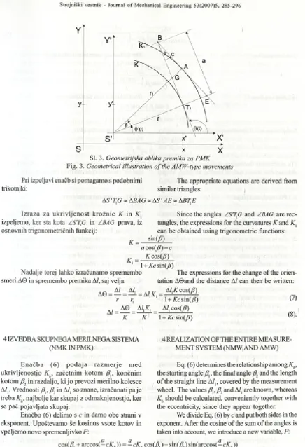
G eo m etrijsk a oblika p rem ika v prim eru poravnanega merilnega kolesca je prikazana na sliki 3.
N a sliki smo si pom agali s premaknjenim koordinatnim sistemom, kjer je S’ središče krožnic, po kateri se giblje robotova referenčna točka (z ukrivljenostjo K), oziroma krožnice, po kateri se giblje d o tik ališče m erilnega kolesca (£ j); £ in G sta pomožni točki.
The geometry o f the robot’s movement is il lustrated in Fig.3.
A translated coordinate system, w here S ’
Sl. 3. Geometrijska oblika premika za P M K
Fig. 3. Geometrical illustration o f the AMW-type movements
Pri izpeljavi enačb si pomagamo s podobnimi The appropriate equations are derived from
trikotniki: similar triangles:
A S ' f G « ABAG « A S' AE « A B f E
Iz ra z a za u k riv lje n o st k ro žn ic K in K } Since the angles Z S ’T fi and /B A G are rec-izpeljemo, ker sta kota /S % G in ZBAG prava, iz tangles, the expressions for the curvatures K and K {
osnovnih trigonometričnih funkcij: can be obtained using trigonometric functions:
K _ s in d ) a c o s (/? )-c
K KcosQff) 1 1 + Kc sin(/?)
Nadalje torej lahko izračunamo spremembo The expressions for the change o f the orien-smeri A© in spremembo premika Al, saj velja tation A©and the distance Al can then be written:
AO = — = — = AIK, A/,Kcos(/?)
(7)
r ri 1 + Kcsin(/?)
Ai =
AQ = AltK A/, cos(/?)(8).
K K l + ALsin(yff)
4 IZVEDBA SKUPNEGA MERILNEGA SISTEMA (NM KINPM K)
E n a č b a (6) p o d a ja ra z m e rje m ed ukrivljenostjo Kb, začetnim kotom /?,, končnim kotom /?, in razdaljo, ki jo prevozi merilno kolesce A/,. Vrednosti ß v ß2 in A/, so znane, izračunati pa je treba Kb, najbolje kar skupaj z odmaknjenostjo, ker se pač pojavljata skupaj.
Enačbo (6) delimo s c in damo obe strani v eksponent. Upoštevamo še kosinus vsote kotov in vpeljemo novo spremenljivko F:
4 REALIZATION OF THE ENTIRE MEASURE MENT SYSTEM (NMW AND AMW)
Eq. (6) determines the relationship among Kb,
the starting angle ß {, the final angle ß2 and the length o f the straight line A/,, covered by the measurement wheel. The values ß v /?, and A/, are known, whereas
Kb should be calculated, conveniently together with the eccentricity, since they appear together.
We divide Eq. (6) by c and put both sides in the exponent. After the cosine o f the sum o f the angles is taken into account, we introduce a new variable, F:
cos(/?, + arccos(— cKh )) = — cKh cost/?, ) - sin(/?, ) sin(arccos(— cKb ))
F = - cK„
sin(arccos(- cKb ))
cKb
1 - £ c K b?
Dobimo enačbo: The following equation is obtained:
1
iz katere izrazimo F:
Sedaj lahko iz ( 10) izračunamo c K,:
E = e ‘
F =
-^ cos( A ) _ ! » M )
c F
from which F can be expressed:
Esinjß^J-sinfßp
E ( - cos(/?2) -1 ) - — cos(/?, ) +1
c c
cKb =±
cKb follows from Eq. (10):
F
(Ta enačba ima dve rešitvi, +cKh in -cK b. Prav tako dobimo dve rešitvi tudi iz enačbe za /2(1), skupaj imamo torej štiri kombinacije vrednosti p a n d cKb.)
(10).
1 H *c F f (U
)-(Since this equation has two solutions, +cKb and cKh,
and two more are obtained from the equation for p Eq. (1), we are left with four combinations o f p a n d cKh.)
4.1 Postopek merjenja 4.1 Measurement procedure
1.
2
.3. 4. 5.
6.
7.
Iz zap iso v aln ik a sm eri preberem o trenutno vrednost kota ßv iz zapisovalnika premika pa premik Al{.
Če je trenutni kot zasuka merilnega kolesca ß2
enak zasuku iz prejšnje meritve ß v je merilno kolesce poravnano v smeri vožnje, primer PMK, zato izračunamo A© in Al iz (7) in (8). Sicer nadaljujemo s točko 3.
Izračunamo vrednost cKb (( 10) in ( 11 )). Določimo kot p = arccos(a/c cKß.
Preverim o kateri p ar {(+p,+cKß,(+p,- cKb),
(-p ,+ cKh),(-p,— cKb)} ustreza (6).
Pravi par vstavimo v enačbo (5) in izračunamo spremembo kota A 0.
Iz spremembe kota A© določimo premik Al: • Če je sprememba kota A© enaka nič, premični
robot vozi naravnost, merilno kolesce pa se poravnava v sm er vožnje: m edtem ko se referenčna točka robota premakne za, recimo, /, se odmaknjenost merilnega kolesca zmanjša z /?! na ß 2. Premik / je podan z enačbo:
2.
3. 4. 5.
/ = c ian(ß\ /2 )
tan(/?2/2 ) (natančna obravnava poravnavanja kolesca
je podana v [3]).
Sicer iz spremembe A 0 in ukrivljenosti Kh
izračunamo premik referenčne točke robota
Al (glej trikotnika AS, TnB t in AA’7 j,5 2 na sliki 2):
Read current values: the value o f angle ß 2 from the steering encoder, and the length A/, from the distance encoder.
I f the current angle ß 2 is equal to the angle /?,, from the previous measurement, the AM W case applies; A© and Al are calculated from Eq. (7) and Eq. (8). Otherwise we proceed with point 3. Calculate cKb (Eq. (10) and Eq. (11)).
Determine p = arccos (ale cKb).
Check which pair among {(+p,+cKß,(+p,- cKß,
(-/?,+ cKb),(-p ,- cKß} correspond to Eq. (6). Put the corresponding pair into Eq. (5) and cal culate the change o f orientation A©.
From A© calculate Al:
• If the change o f the orientation A© is zero, the mobile robot drives along a straight line, while the measurement wheel is still aligning with the direction o f the drive: if the reference point moves by, for example, /, the nonalignment o f the measurement wheel is decreased from /?, to ßY The move / is defined by the equation:
(the complete explanation is given in [3]).
• Otherwise, calculate the movement o f the ro bot’s reference point Al, using A© and the curvature Kb (observe the triangles AS, TuB l
Al = A®.
8. Iz spremembe kota A© in premika A/ izračunamo z uporabo dobro znanih razmerij spremembo p o lo žaja prem ičn eg a ro b o ta v k artezičnem koordinatnem sistemu.
5 DOLOČITEV PARAMETROV POLOŽAJNEGA SISTEMA
O p isan o p o lo ž a jn o z a z n a v alo zah tev a določitev vrednosti štirih parametrov: odmaknjenost
c, ničelni kot ßQ (kot, ki ga kaže zapisovalnik smeri pri vožnji naravnost), obseg m erilnega kolesca o,, oddaljenost položajnega zaznavala od referenčne točke robota a.
N a začetku m oram o te param etre seveda določiti ročno, toda tako dobljene vrednosti so le grobe ocene; natančnejše vrednosti določim o tako, da robot vozi po poteh, pri katerih se vpliv posam eznih param etrov čim bolj osami. Pri vožnj i naravnost, na prim er, param eter a ne vpliva kaj dosti, vsak od preostalih treh pa vpliva drugače. Z a d o lo č ite v v re d n o sti p a ra m e tro v sm o zato iz b ra li p ra v v o ž n jo n a ra v n o st. Ob n jej sm o sprem ljali potek robotove lege in g ra f usm eritve ro b o ta 0 . G rafi izm erjenih leg robota in njegove usm eritve so potrdili, da odm aknjenost c vpliva sa m o na z a č e tk u , ko m e riln o k o le sc e še ni p o r a v n a n o , da n ič e ln i k o t ß 0 d o lo č a n ag ib sprem injanja kota © (ki bi pri vožnji naravnost sicer m oral ostati stalen) ter da obseg kolesca o x
n e vp liv a bistveno na sprem injanje 0 , občutno p a vp liv a na dolžino poti.
Podrobnejše rezultate param etrične analize si lahko ogledamo v [3], kjer je tudi razloženo, zakaj m o ra b iti v r s tn i re d d o lo č a n ja p a ra m e tro v naslednji: c, ß0 in o]. Parameter a določimo z vožnjo po krogih.
K er je položajno zaznavalo zasnovano na relativnem merjenju, se njegova napaka neprestano povečuje, zato je zelo pomembna ocena njegovih parametrov. V našem primeru so končne vrednosti param etrov bile: ß0 = 196,708°, c = 0,04014 m, ox = 0,2985 m in a = 0,5678 m. Vse so bile seveda pridobljene programsko, na temelju testnih voženj robota.
( y
- a 2
\°K-b j
8. The change o f the robot’s position in the Carte sian coordinate system is calculated from A© and Al using the well-known relations.
5 DETERMINATION OF THE PARAMETERS OF THE SENSOR
The position sensor requires the determination o f four parameters: the eccentricity c, the zero angle ßü
(the angle, the steering encoder reports when the ro bot is moving straight ahead), the circumference of the measurement wheel op and the distance from the posi tion sensor to the reference point of the robot a.
At the beginning these parameters have to be determined manually, yet these are only coarse ap proximations o f the real values; the finer values are obtained by letting the robot move along the kind of paths on which the impact o f the individual parameter is isolated as much as possible. If the robot moves along the straight line, for example, parameter a does not have much influence, while each o f the remaining affect the movement in their own way. That is why we chose exactly this type o f movement to determine the parameters values. The robot’s position and the graph o f its orientation were observed carefully along the path. The graphs o f these positions and orientations proved that the eccentricity c has an impact at the beginning only, when the measurement wheel is still not aligned, that zero angle ßn determines the inclina tion o f the 0 graph, which should stay constant, when moving straight ahead- constant, and that circumfer ence o f the wheel ox does not have an observable impact on the graph 0 , but it does have a substantial influence on the length o f the paths.
Detailed result's o f the parametric analysis can be found in [3], where the explanation as to why the order o f the parameter determination should be
c, ß0 and o , is given. The parameter a is determined
by the circular paths.
6 REZULTATI 6 RESULTS
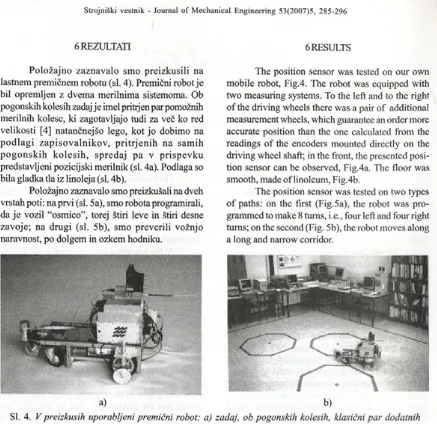
P o lo žajn o zaznavalo sm o preizkusili na lastnem premičnem robotu (sl. 4). Premični robot je bil opremljen z dvem a merilnima sistemoma. Ob pogonskih kolesih zadaj je imel prihjen par pomožnih m erilnih kolesc, ki zagotavljajo tudi za več ko red velikosti [4] natančnejšo lego, kot jo dobimo na p o d la g i z a p iso v a ln ik o v , p ritrje n ih na sam ih p o g o n s k ih k o le s ih , sp red aj p a v p risp e v k u predstavljeni pozicijski merilnik (sl. 4a). Podlaga so bila gladka tla iz linoleja (sl. 4b).
Položajno zaznavalo smo preizkušali na dveh vrstah poti: na prvi (sl. 5a), smo robota programirali, da je vozil “osmico”, torej štiri leve in štiri desne zavoje; na drugi (sl. 5b), sm o preverili vožnjo naravnost, po dolgem in ozkem hodniku.
The position sensor was tested on our own mobile robot, Fig.4. The robot was equipped with two measuring systems. To the left and to the right o f the driving wheels there was a pair o f additional measurement wheels, which guarantee an order more accurate position than the one calculated from the readings o f the encoders mounted directly on the driving wheel shaft; in the front, the presented posi tion sensor can be observed, Fig.4a. The floor was smooth, made o f linoleum, Fig.4b.
The position sensor was tested on two types o f paths: on the first (Fig.5a), the robot was pro grammed to make 8 turns, i.e., four left and four right turns; on the second (Fig. 5b), the robot moves along a long and narrow corridor.
a) b)
SI. 4. V preizkusih uporabljeni premični robot: a) zadaj, ob pogonskih kolesih, klasični par dodatnih merilnih kolesc; spredaj, v prispevku predstavljeno zaznavalo; b) vožnja v laboratoriju
Fig. 4. The mobile robot from the experiments: a) at the back, on each side o f the driving wheels, a pair o f classical measurement wheels, at the front, the proposed sensor, b) the drive in the laboratory
SI. 5. Dve vrsti poti: a) osmica, b) dolg in ozek hodnik
6.1 Prva vrsta poti: osmica 6.1 The first type: figure-of-eight path
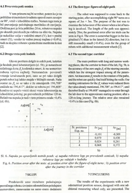
V tem primeru naj bi se robot, potem k o je na približno trimetrskem kvadratu opravil osem zavojev za 90°, vrnil v izhodiščno točko. Namen tega testa je bil preveijanje položajnega merilnika ob zavijanju. Dolžina poti je bila približno 20 m, robotovo napako po desetih preizkusih pa vidimo na sliki 6a. Napaka je nekoliko večja v vzdolžni smeri (Y), kot v prečni smeri (X), vendar še vedno precej majhna (<0,4%), tudi za skupino robotov s pomožnimi merilnimi kolesi
[21
The robot was supposed to come back to the starting point, after accomplishing eight 90° turns on a square of 3m x 3m. The purpose o f the test was to examine the behaviour o f the sensor when a lot of turn ing is involved. The length o f the path was approxi mately 20m; the positional error after ten trials can be seen in Fig.6. The error is somewhat bigger in the lon gitudinal (Y) than in the lateral (X) direction, but it is still reasonably small (0 .4 % ), even for the group of robots with additional measurement wheels [2].
6.2 Druga vrsta poti: hodnik
Glavni problem dolgih in ozkih poti, kakršen je hodnik pred laboratorijem (sl. 5b), je natančnost ničelnega kota ß0 kodim ika smeri, ki na usm eritev ro b o ta v p liv a n ajb o lj. N e n a ta n č en p o v zro či vrtenje izračunanih poti, zato se pri tako dolgih poteh robot kaj lahko znajde v bližnjih stenah. Naše ocene za ß f) so se tako z že om enjenih 196,708° znižale na 196,617°, dokler se robotu pri 196,608° končno ni uspelo vrniti skozi vrata laboratorija na izhodiščni položaj ; po prevoženih približno 120 m. Relativna napaka je tudi v tem primeru ostala <0,4% (sl. 6b).
Ay[cm] ° °o
o OOo
o o
o
H---+--- h --- 1---1---1--- 1---1--- h— ? Ax[cm]
a)
6.2 The second type: corridor
s
The main problem with long and narrow work ing places, like the corridor in front o f the lab, Fig. 5b, is the accuracy o f the zero angle ß() of the steering encoder, which has the strongest impact among all the param eters. An inaccurate ß0 results in the rotation o f the paths, and the robot can quickly find itself hitting the walls. Our starting estimations for the ß0 values were reduced from the value already mentioned, 196.708°, to 196.617°, until the robot finally at 196.608° managed to re-enter through the lab door to the approximate starting position; after a 120-m-long journey. The relative error also remained <0.4% in this case (Fig. 6b).
Št. preizkusa Exp. no.
A* [m] A yM
1 -0,101 -0,309
2 0,079 0,430
3 0,024 0,261
4 1 0,068 0,372
b)
SI. 6. Napaka po opravljenih testnih poteh: a) napaka robotove lege po prevoženih osmicah; b) napaka
robotove lege po vožnjah v hodniku
Fig. 6. Position error after the tests: a) position error after the figure-of-eight turns ; b) position error after the journey in the corridor
7 SKLEPI 7 CONCLUSIONS
P re d sta v ili sm o re z u lta te p o lo ž a je n ja premičnega robota z izvirnim odometričnim položajnim zaznavalom, zasnovanim na samo enem dodatnem
merilnem kolescu. Položajno zaznavalo sestavljata absolutni kodimik za metjenje usmeijenosti merilnega kolesca in relativni kodimik za merj enje prevožene poti. Preizkusi so pokazali, da je predlagano zaznavalo v natančnosti povsem primerljivo običajni rešitvi z dvema dodatnima merilnima kolescema ob pogonskih kolesih. Njegova prednost pa je v tem, da ga lahko namestimo na poljubnem mestu na robotu, zato je uporabnik z njegovo namestitvijo bistveno manj omejen. Pravzaprav bi lahko robota opremili celo z več takimi zaznavali in njihove rezultate povprečili.
Težavo pri uporabi pa pomeni razmeroma zamudno določanje vrednosti štirih parametrov: ß0,
c, o t in a.
N a prvi pogled se zdi, da bi bila lahko težava, ali pa vsaj omejitev, morebitna neporavnanost med usm erjenostjo robota in izmaknjeno nameščenim merilnim kolescem zaznavala ob vklopu robota: izkaže se, da matematični opis v primeru N M K povsem zadovoljivo podaja položaj tudi v tem primera. Kako je merilno kolesce zasukano, torej ni treba skrbeti niti pred prvo vožnjo.
sensor consists o f an absolute encoder, which m eas ures the orientation o f the measuring wheel, and o f a relative optical encoder, which measures the length o f the path. Experiments proved the proposed sen sor to be completely comparable to the classical so lution with two measurement wheels mounted on each side o f the driving wheels. However, it has the advantage that it can be mounted at an arbitrary place around the robot, so the user is far less re stricted in terms o f its use. In fact, one could equip the robot with even more position sensors and aver age their results.
The main problems associated with its use relate to the determination o f its four parameters, ß 0, c, o, and a.
At first sight it appears that the problem m ight be a possible misalignment o f the orientation o f the robot and the eccentrically m ounted m easuring wheel; however, it turned out that the discussion given in the case o f NM W also holds good in this example. The actual orientation o f the m easuring wheel is not a problem, even before the first run.
8 LITERATURA 8 LITERATURE 1 2 3 4 5 6 7
[1] J.Borenstein, H.R.Everett, L.Feng (1996) Navigating mobile robots-systems and techniques, A K Peters,
Wellesley, M assachusetts.
[2] J.Borenstein, L.Feng (1994) UMBmark - a method for measuring, comparing and correcting dead-reckoning errors in mobile robots, Technical Report UM-MEAM-94-22, University o f Michigan.
[3] M .Blatnik (1996) Navigacija mobilnega robota z enim merilnim kolesom, Diplomsko delo, Fakulteta za
računalništvo in informatiko, Ljubljana.
[4] Z.Fan, J.Borenstein, D. Wehe, Y.Koren (1995) Experimental evaluation o f an encoder trailer for dead reckoning in tracked mobile robots. Proc. o f the 10th IEEE Int.Syposium on Intelligent Control.
[5] J.Borenstein (1994) Internal correction o f dead-reckoning errors with smart encoder trailer, Proc. o f
International Conf. on Intelligent Robots and Systems (IROS’94), Munich, Germany, September 12-16,
1994, str. 127-134.
[6] R.Mahkovic, T.Slivnik (2000) Constructing the generalized local Voronoi diagram from laser range scanner data, IEEE Transactions on Systems, Man, and Cybernetics, let.30, št.6, str.710 - 719,2000.
[7] N.S.V.Rao, S.Kareti, S.S. Iyengar (1993) Robot navigation in unknown terrains: Introductory survey o f non-heuristic algorithms. Tecnical report, oml/tm-12410, Oak Ridge National Laboratory, Oak Ridge, Tennessee, 37831.
Avtoijev naslov: doc. dr. Rajko Mahkovic Univerza v Ljubljani
Fakulteta za računalništvo in informatiko
Tržaška 25 1000 Ljubljana
A uthor’s Address: Doc. Dr. Rajko Mahkovic University o f Ljubljana Faculty o f Computer and Information Science Tržaška 25
1000 Ljubljana, Slovenia [email protected]
Odprto za diskusijo: 1 leto Open for discussion: 1 year Prejeto:
Received: 15.3.2006
Sprejeto: