0 INTRODUCTION
The deep drawing process is widely used for forming sheet metal products. Medication and perfume tubes, pots and pans, household appliances, automotive parts and defence industry products are examples of the different applications of this process. In products formed using deep drawing, homogenous sheet thickness distribution and achievement of the highest drawing ratio is expected.
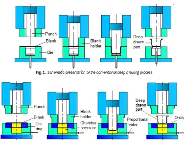
Conventional deep drawing is one of the most widely used sheet metal-forming methods for turning blank sheets into hollow pieces. The process includes forming the sheet metal with compression and tensile forces. In the process, the punch pulls the sheet material through the space between the punch and the die ring and shapes it [1]. In this process, the blank-holding slide transfers the blank-blank-holding force via the blank holder onto the blank and the draw die. The die and the ejector are located in the lower die on the press bed. During forming, the blank holder brings the sheet metal into contact with the die, the punch descends from above into the die and shapes the part, while
the sheet metal can flow without any wrinkling of the blank-holding area. In this case, the drawing process is carried out with a fixed blank holder and moving punch. The conventional deep drawing process is shown schematically, in Fig. 1.
When analysing previously performed studies, it was found that there are experimental-analytical and numerical research results. Through the finite element method (FEM), which is a numerical method, Volk et al. attempted to determine the optimal blank-holding force, through the finite element method, by changing the geometry and the structure of the blank holder. The best results were obtained with flexible, segmented blank holders [2]. Trzepieciński and Lemu worked on the effect of sheet metal surface roughness, lubricant conditions and sample orientation on the value of the friction coefficient in the draw-bead region of the sheet metal-forming processes. They ascertained several relationships showing the effect of surface profile and lubrication on the value of the friction coefficient. Simulations have been performed to study the stress/strain state in the stretched sample during draw-bead simulator tests [3]. Assempour and
The Experimental Investigation of Effects
of Multiple Parameters on the Formability
of the DC01 Sheet Metal
Gürün, H. – Karaağaç, İ. Hakan Gürün* – İbrahim Karaağaç
Gazi University Faculty of Technology, Department of Manufacturing Engineering, Turkey
The formability of sheet metal materials through the deep drawing process is affected by various parameters, such as die chamber pressure, die radius and sheet thickness, all of which directly influence the product’s quality. This paper investigates the formability of the DC01 sheet metal material. DC01 is a carbon steel sheet, which has a wide range of usages from the automotive industry to the manufacture of radiators by means of hydro-mechanical and conventional deep deep drawing methods. This study, for the first time, empirically investigates the effects of die chamber pressure, die radius and sheet thickness on the formability of DC01 sheet metal material through hydro-mechanical and conventional deep deep drawing methods. The study also helps to determine the forming parameters for this material. With regard to the hydro-mechanical deep drawing process, the drawing ratio increased from 2.16 to 2.33, solely due to an increase in die chamber pressure. The results of the experiment revealed suitable forming parameters through hydro-mechanical and conventional deep drawing methods for samples of DC01 material having a cylindrical geometry.
Keywords: deep drawing, hydro-mechanical deep drawing, conventional deep drawing
Highlights
• The effects of die chamber pressure, die radius, and sheet thickness on the formability of DC01 sheet metal material were empirically investigated.
• The formability properties of DC01 sheet material were compared using conventional and hydro-mechanical deep drawing processes.
• The effect of each parameter and suitable parameter values were empirically identified and evaluated. • The biggest drawing ratio in the hydro-mechanical deep drawing process was obtained as 2.33. • The biggest drawing ratio in the conventional deep drawing process was obtained as 2.16.
Taghipour worked to evaluate the effect of normal stress in the hydromechanical deep drawing (HDD) process. Analyses were carried out for axisymmetric elements of the formed cup-shaped part for increments of the punch travel. They found some differences between thickness values, radial and circumferential strains and stresses, and punch force under plane stress and three-dimensional stress conditions [4].
Numerical simulation methods were also used to aid in the development of the forming tool and the determination of the process parameter. Jurendić and Gaiani developed a numerical simulation method to aid in forming tool development and process parameter determination. They used the Barlat 1989 material model and employed an experimental strain-hardening curve to consider the anisotropic strain-hardening of the material [5]. Garcia et al. used a Hill-48 associate plasticity model to analyse the modelling and experimental validation of the Erichsen test, a cylindrical cup test, and an industrial sheet metal-forming process [6].
The hydro-mechanical deep drawing process is forming using liquid pressure. Hydromechanical deep drawing (HDD), as a combination of conventional deep drawing with sheet hydroforming, has been widely used in the forming of complex-shaped
sheet materials [7]. Onder and Tekkaya worked to determinate the optimum sheet metal-forming process and process parameters for various cross-sectional workpieces by comparing the numerical results of high-pressure sheet metal forming, hydromechanical deep drawing and conventional deep drawing simulations. The analyses revealed that certain processes are preferable for obtaining satisfactory products depending on the workpiece geometry and dimensional properties. Furthermore, it has been found that hydromechanical deep drawing is mostly suitable for deeper products where the flange is large [8]. Khandeparkar and Liewald worked on the advantages of hydro-mechanical deep drawing, such as increased deep drawing ratio, transfer of complex contours from a punch to the blank surface, reduction of drawing stages and better part quality. The process was simulated using the LS-DYNA FEM solver [9]. Sharma and Rout developed a finite element (FE) model for simulating the sheet hydromechanical forming process using LS-DYNA dynamic explicit commercial code. The analysis revealed that higher cup depth with minimum thinning, for forming dominated by stretching mode, can be achieved with material of a higher anisotropy ratio and strain hardening exponent by using a rough punch and
Fig. 1. Schematic presentation of the conventional deep drawing process
effective lubrication at blank-die-blank holder interfaces [10].
As shown in Fig. 2, the lower die is a pressure medium reservoir or water container or chamber. The upper part of the die consists of the blank holder and the draw punch. In this process, to form the sheet metal the forming punch moves toward a high-pressure liquid mass in a controlled manner. As the drawing punch enters the chamber filled with the liquid, the pressure of the fluid starts to increase. During the deformation, the sheet material is pressed around the drawing punch. The pressure activated through the entry of the drawing punch into the pressured liquid has a multi-directional effect. Because of the pressure, the sheet material is forced to wrap around the punch. As a result of this force, the friction between the punch and the sheet material increases. This increase in the friction prevents the sheet material from irregularly tapering and being torn or cracked. As a result of the pressure inside the die, the drawing forces reach a higher level than what is expected from the conventional deep drawing process [11] and [12]. The hydro-mechanical deep drawing process is shown schematically, in Fig. 2.
With the use of the DC01 sheet material, many products in different sectors are being produced using the deep drawing process. Because the sheet material has widespread usage, it was chosen as the experimental material. The aim of this experimental study is to find the forming parameters that allow achieving the highest experimentally observed forming of a drawing ratio. Furthermore, it was aimed comparison of formability properties of DC01 sheet material using conventional and hydro-mechanical deep drawing processes in terms of drawing force. By identifying ideal forming parameters, trial and error,
and the preparation that take place in the production of a product can be eliminated, reducing the product and die costs for similar geometry and forming parameters.
1 MATERIAL AND METHODOLOGY
1.1 Experimental Setup
Experimental studies were conducted using the experimental setup that was designed, produced and calibrated. The experimental setup was designed to be able to use both the conventional and hydro-mechanical forming processes and realize the process of data acquisition in real time while being controlled electromechanically.
In general, the experimental setup has three main parts: mechanical construction and dies; hydraulic power unit; and electronic control and data acquisition software. The experimental setup is shown in Fig. 3.
The mechanical components of the experimental setup are the main construction, forming punch, blank holder, die group, and a liquid chamber. A detailed schematic of the mechanical construction of the experimental setup, die group, and liquid chamber is shown in Figs. 4 and 5, respectively.
The electronic control of the experimental setup and data acquisition process is done through software and a data acquisition card. The imposed forming speed, punch displacement, blank holder force and chamber pressure are entered into the system through the designed software. Forming speed can be adjusted via the speed adjustment valves controlling the forming cylinders. The punch displacement is observed using the coordinate reader scale connected to the punch cylinder; when the displacement entered by the user is achieved, the process is complete. The
blank holder force can be observed and controlled via the pressure of the cylinders controlling the blank holder, which is adjusted using the pressure adjustment valve. The forces read from the load cells, according to the configured pressure value, are simultaneously observable using the software. The control of chamber pressure is done through the reading of data collected from a pressure transducer inside the die. This reading is compared to the value entered into the software, leading to the opening and closing of the proportional pressure valve that controls the pressure inside the die until the expected value is achieved. Fig. 6 shows a screenshot of the software designed for data acquisition and electronic control.
In the hydro-mechanical deep drawing experiments, hydraulic oil that conforms to ISO 11158 standard with a kinematic viscosity of 46 mm/s² at 40
°C (Hydro-Oil Aw 46, Petrol Ofisi, Turkey) was used as the forming liquid.
1.2 Experimental Study
In the experimental study, the parameters that are effective in the forming processes and that need to be inspected were primarily identified. The values of the identified parameters are:
• Sheet thickness, t [mm]: 0.5, 0.8 and 1.0. • Die radius, r [mm]: 4, 6 and 8.
• Chamber pressure, p [MPa]: 10, 20 and 30. • Initial blank diam. D [mm]: 120, 130 and 140. • Punch shape and size: cylindrical, Ø60 mm. • Punch velocity, v: 6 mm/s.
Mechanical and chemical specifications of the experimental material have been obtained through the identification of experimental parameters. To obtain the mechanical properties, tensile test samples
Fig. 6. Hydromechanical deep drawing experimental setup control software
Fig. 4. Detailed view of the mechanical construction of experimental setup
with 1 mm sheet thickness in ASTM E8-M standards have been prepared in 0°, 45° and 90° to the rolling direction and have been subjected to tensile tests, which were done three times in each direction. Fig. 7 shows images of the experimental samples on which the tensile tests were done.
Fig. 7. DC01 sheet material tensile test experimental samples
The material in which the same properties are measured in any direction is termed isotropic, but most industrial sheets will show a difference in properties measured in test-pieces aligned with the rolling direction, and at 90° and 45° to the rolling direction. Different material properties working in different directions can have a significant effect on the degree of difficulty of the forming operation. In particular, the textures and orientation of the crystal structure to the rolling direction of the sheet metal lead to anisotropic directional behaviour. The anisotropy of the plastic behaviour of sheet metals is characterized by the Lankford’s coefficient r [13], which is determined by uniaxial tensile tests. In such tests, the ultimate tensile results are achieved in the rolling direction. In the case of a 45° direction, tensile stress decreased, and in the case of a 90° direction, the lowest values of tensile stress were obtained. The results of tensile tests were used only to determine the blank holder forces. The tensile stress values obtained as a result of the tests is shown in Table 2; the other properties of the sample are shown in Table 3, and the chemical composition of the material is shown in Table 4.
The recommended drawing speed value between 5 mm/s to 10 mm/s for hydro-mechanical deep drawing processes was found in the relevant literature
[14] to [18]. In the experimental study, the drawing speed for the forming DC01 sheet material using hydro-mechanical deep drawing was kept constant at 6 mm/s. The blank holder force was kept constant during the experimental study. In the study, constant blank holder force values for both conventional and hydro-mechanical deep drawing processes were calculated separately. In the calculation of the blank holder pressure value used in the conventional deep drawing experiments Eq. 1 was used and in the calculation of the blank holder pressure value used in the hydro-mechanical deep drawing experiments Eq. 2 was used. In the calculation of blank holder forces for both processes, Eq. 3 was used. The blank holder forces used in experimental studies are given in Table 5.
Table 2. Sample orientation with respect to roll direction
DC01
Rolling Direction
0 ° 45 ° 90 °
Ultimate tensile stress [MPa] 1. Test 360.6 344.1 342.3 2. Test 356.5 344.8 339.6 3. Test 356.9 345.9 340.6
Blank holder pressure p [1]:
p = [(β–1)2 + D / 200t] · (Rm / 400) , (1) p = 0.002 [(β– 1)2 + D / 200t] · Rm , (2) where β is the drawing ratio, D is the initial blank diameter, t is sheet material thickness [mm] and Rm is the ultimate tensile stress.
Blank holder force FBH[1]:
FBH = (ABH) (
p
)
, (3)where ABH is the area the blank holder is effective on the sheet material [mm2] and p is the blank holder pressure.
The one-sided space measured between die and punch in deep drawing dies is called the drawing clearance. In the experimental studies, dies with different drawing clearances for each sheet material thickness (t = 0.5 mm, t = 0.8 mm, t = 1.0 mm) were
Table 3. DC01 sheet material mechanical properties
Material Tensile stress [MPa] Yield stress [MPa] Elongation [%] Modulus of elasticity [GPa] Poisson rate Specific gravity, [g/cm3]
DC01 350.0 253.0 18.81 142.0 0.28 7.83
Table 4. Chemical composition of DC01 sheet material
Material C [%] Mn [%] P [%] S [%] Cr [%] Fe [%] Others %
Table 5. Blank holder forces
Hydro-mechanical deep drawing Conventional deep drawing Sheet thickness, t Sheet thickness, t
0.5 mm 0.8 mm 1.0 mm 0.5 mm 0.8 mm 1.0 mm
Inıtial Blank Diameter Blank Holder Force [kN] Blank Holder Force [kN]
120 mm 13.056 10.385 9.495 16.320 12.981 11.869
130 mm 19.448 15.885 14.697 24.310 19.856 18.372
140 mm 27.939 23.323 21.784 34.923 29.154 27.230
Table 6. Experimental results obtained using the hydro-mechanical deep drawing process
Sheet material: DC01
Die radius, r: 4 mm Die radius, r: 6 mm Die radius, r: 8 mm Chamber pressure [MPa] Chamber pressure [MPa] Chamber pressure [MPa]
10 20 30 10 20 30 10 20 30
D: 120 mm, t = 1.0 mm √ √ √ √ √ √ √ √ √
D: 130 mm, t = 1.0 mm √ √ √ √ √ √ √ √ √
D: 140 mm, t = 1.0 mm × × × × √ √ √ √ √
D: 120 mm, t = 0.8 mm √ √ √ √ √ √ √ √ √
D: 130 mm, t = 0.8 mm √ √ √ √ √ √ √ √ √
D: 140 mm, t = 0.8 mm × × × √ √ √ √ √ √
D: 120 mm, t = 0.5 mm √ √ √ √ √ √ √ √ √
D: 130 mm, t = 0.5 mm √ √ √ √ √ √ √ √ √
D: 140 mm, t = 0.5 mm X √ √ √ √ √ √ √ √
(√: Successful forming process, ×: Tearing and unsuccessful forming process)
produced. The calculation of the drawing clearances between the die and the punch is given by:
w = t + k , (4) where w is drawing clearance value [mm], t is sheet thickness [mm] and k is material constant (k = 0.07 mm for steel material [1] and [13]. The drawing-clearance values were calculated according to sheet material thickness and used in the experimental study.
Experimental studies have been conducted using both the conventional and the hydro-mechanical deep drawing processes according to the identified experimental parameters. In the study, 27 experiments for the conventional drawing process and 81 experiments for the hydro-mechanical deep drawing process were done. For trials using both methods, each experiment was repeated three times.
2 RESULTS
The results obtained from hydro-mechanical deep drawing experiments are shown in Table 6, and the results obtained from conventional deep drawing experiments are shown in Table 7. The obtained results have been evaluated according to the effects of chamber pressure, die radius, and sheet material
thickness experimental parameters to the drawing ratio and the drawing force.
Table 7. Experimental results obtained using the conventional deep drawing process
Sheet Material: DC01 Die radiusr: 4 mm Die radiusr: 6 mm Die radius r: 8 mm
D: 120 mm, t = 1.0 mm √ √ √ D: 130 mm, t = 1.0 mm √ √ √ D: 140 mm, t = 1.0 mm × × ×
D: 120 mm, t = 0.8 mm √ √ √ D: 130 mm, t = 0.8 mm × √ √
D: 140 mm, t = 0.8 mm × × ×
D: 120 mm, t = 0.5 mm √ √ √ D: 130 mm, t = 0.5 mm × × ×
D: 140 mm, t = 0.5 mm × × ×
(√: Successful forming process, ×: Tearing and unsuccessful forming process)
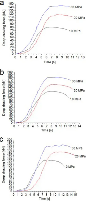
process, a maximum drawing ratio of 2.16 was obtained using the conventional deep drawing process. More than one reason was observed for the fact that the drawing ratio for the hydro-mechanical deep drawing is larger than that for the conventional drawing process. In the hydromechanical deep drawing process, as the forming medium is lubricated, the friction between the sheet material and the die lessens, and the forming process becomes easier. In contrast, the pressure created inside the die presses the sheet metal into the punch, increasing the friction between the sheet metal and the punch, thus preventing it from tearing as a result of non-homogeneous thinning of the material. As the pressure inside the die is the same on the sheet material from all directions, non-homogeneous thinning is again prevented. Another function of the pressure inside the die is observed as the die radius friction is reduced, and the forming is improved, resulting from the sheet material being pressured toward the punch. The effect of chamber pressure was observed clearly in the experimental study regarding the hydro-mechanical deep drawing process. In this study, while for 0.5 mm sheet material thickness, a 4 mm die radius and 10 MPa chamber pressure, a maximum of 2.16 drawing ratio could be obtained, as the chamber pressure was increased to 20 MPa, a maximum of 2.33 drawing ratio was obtained. In another experimental group, while at 1.0 mm sheet material thickness, 6 mm die radius and 10 MPa chamber pressure a maximum drawing ratio of 2.16 could be obtained, as the chamber pressure was increased to 20 MPa, a maximum drawing ratio of 2.33 was obtained. Images of sheet materials shaped in different drawing ratios in the experimental study are shown in Fig. 8. It was observed that as the chamber pressure is increased, the drawing force is increased, this being a result of the force being in the reverse direction of the punch movement. The punch
forces obtained using 0.5 mm, 0.8 mm, and 1 mm sheet material thicknesses with 4 mm die radius and 120 mm initial sheet material diameter at chamber pressures of 10 MPa, 20 MPa, and 30 MPa in the experimental studies are given in Fig. 9.
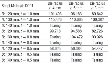
Table 8. Punch forces of the conventional deep drawing process, kN
Sheet Material: DC01 Die radiusr: 4 mm Die radiusr: 6 mm Die radiusr: 8 mm
D: 120 mm, t = 1.0 mm 101.493 96.163 89.642
D: 130 mm, t = 1.0 mm 115.426 110.665 106.382
D: 140 mm, t = 1.0 mm Tearing Tearing Tearing
D: 120 mm, t = 0.8 mm 99.718 94.588 82.726
D: 130 mm, t = 0.8 mm Tearing 104.472 99.926
D: 140 mm, t = 0.8 mm Tearing Tearing Tearing
D: 120 mm, t = 0.5 mm 58.625 56.384 54.447
D: 130 mm, t = 0.5 mm Tearing Tearing Tearing
D: 140 mm, t = 0.5 mm Tearing Tearing Tearing
Fig. 9. Deep drawing force at different sheet material thicknesses and chamber pressures; a) t = 0.5 mm, b) t = 0.8 mm, c) t = 1.0 mm
Fig. 10. Forming forces at different die radius measures (D=130 mm, p=10 MPa); a) t=0.5 mm, b) t=0.8 mm, c) t=1 mm
In the conventional deep drawing process, while 0.8 mm sheet material thickness, a 130 mm initial sheet material diameter experimental sample could not be formed with a 4 mm die radius when the die radius value was increased to 6 mm, the forming process could be completed. In Fig. 10, the forming forces, obtained at different die radius values belonging to forming studies at different die radii are shown. The punch forces obtained from conventional deep drawing processes have been given in Table 8.
It can be observed that as sheet material thickness increases, the drawing ratio increases. The drawing
Fig. 11. Forming studies at different die radii using hydro-mechanical deep drawing process-1; D = 140 mm, p = 10 MPa, t = 0.5 mm, a) r = 8 mm, b) r = 6 mm, c) r = 4 mm
Fig. 12. Forming studies at different die radii using hydro-mechanical deep drawing process-2 D = 140 mm, p = 10 MPa, t = 0.8 mm, a) r = 8 mm, b) r = 6 mm, c) r = 4 mm
Fig. 13. Forming studies at different die radii using conventional deep drawing process D = 130 mm, t = 0.8 mm, a) r = 8 mm b) r = 6 mm c) r = 4 mm
pressure causes a large contact area on the die radius. In this case, the effect of the most important parameter of the hydro-mechanical forming process, chamber hydraulic liquid pressure decreases, and the positive effect chamber pressure provides to the forming process cannot be fully observed. In the deep drawing process, a thickness increase in the sheet material postpones wrinkling and lets the sheet
In the deep drawing process, tearing is an important aspect: tears with higher amplitude were observed in the conventional deep drawing process.
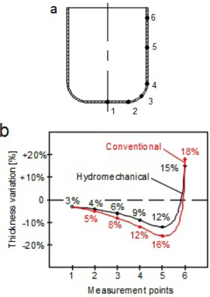
In the formability of sheet metal materials, the control of thickness change is an important parameter that can affect product quality. Minimum thickness change indicates that the forming of the product has been done successfully. Cups with the maximum drawing ratio value obtained in experimental studies were cut on a wire EDM in order to examine thickness change, which were measured from the measurement points indicated in Fig. 14a using a 0.01 sensitive micrometer. Measurement results are given in Fig. 14b.
Fig. 14. Thickness variation measurements of DC01 sheet material a) measurement points, b) measurement results
Maximum thickness thinning was observed at the ending points of the punch radius (4th point) and wall (5th point) for both processes. However, an increase in thickness was observed at the flanges (6th point). In the hydro-mechanical deep drawing method, because the contact to sheet material shaped by the liquid is the same in every direction, the unstable thinning of the sheet material is prevented; thus, thickness change is more homogeneous compared to the conventional deep drawing process.
In the investigation of the experimental specimens’ thickness change, it was observed that the thinning in thickness change did not exceed 12% in the hydro-mechanical deep drawing process. This result shows that thickness change in the product is considerably homogeneous compared to the conventional forming method.
3 DISCUSSIONS
This is the first study in which the effects of parameters such as die radius, sheet thickness and die chamber pressure affecting the formability of DC01 sheet metal material through hydro-mechanical and conventional deep drawing methods are together empirically investigated. The rate of the effect of each parameter and suitable values of these parameters were empirically identified and evaluated. The results of the study are provided below.
Die chamber pressure is a key parameter in the forming processes of the hydro-mechanical deep drawing method. Prebulge pressure is usually applied in the hydro-mechanical deep drawing method in order to avoid and decrease in advance the sheet material contacting the die radius, thus helping to increase the drawing ratio. In the empirical study, die chamber pressure tended to increase once the punch penetrated into the die. The present study yielded the smallest die radius of 4 mm and a drawing ratio of 2.33 at the smallest die thickness of 0.5 mm for DC01 sheet material, although prebulge pressure had been applied in advance. In conventional drawing experiments, the highest drawing ratio, 2.16, was obtained in 0.8 mm and 1.0 mm thick sheets, which are the higher sheet thicknesses, or in bigger die radiuses.
Die chamber pressure, die radius, and sheet material thickness affect the forming force. In the hydro-mechanical deep drawing method, a higher drawing force is obtained because the die chamber pressure generates a reverse force on the punch. If the die chamber pressure is increased by 10 MPa, the forming force increases by approximately 30 kN. An increase in the die radius causes a decrease in the forming force. This arises because the sheet material is exposed to less tension at a higher die radius size. Where die radius increases by 2 mm, forming force decreases by approximately 5 kN.
material has decreased contact with the die radius. This contributes to obtaining better surface quality in the parts that are formed. Although the empirical studies did not go as far as extremely high die chamber pressure values (>30 MPa), the sheet material could be drawn to the end without any wrinkles on it. In the conventional forming methods, however, scratches appearing on the punch along with the scratches and burrs on the sheet material are among the factors that decrease formability and surface quality.
The thickness of sheet material is an important parameter in the drawing and forming processes. Die chamber pressure and sheet material thickness are closely related parameters, and die chamber pressure must be specified according to sheet material thickness during the hydro-mechanical deep drawing process. Die chamber pressure in the hydro-mechanical deep drawing process must have a value that will uniformly press the sheet material on the punch and decrease its contact with the die radius. Otherwise, the impact of the hydro-mechanical deep drawing process could not be notably observed. In empirical studies, the biggest drawing ratio, 2.16, was obtained in 0.8 mm thick sheet material and at a die radius of 4 mm under 20 MPa of die chamber pressure, while a drawing ratio of 2.33 was obtained in the 0.5 mm thick sheet material under the same conditions. It was due to the fact that the effect of die chamber pressure increases as the sheet material thickness decreases.
As the value of the die radius increases, the formability of the sheet material also increases. However, the impact of the die radius may decrease in the hydro-mechanical deep drawing method under high die chamber pressure in case of elimination of the contact between the die radius and the sheet material due to the pressure. In the empirical studies, the effect of the die radius was fully observed in both methods. It was also observed that as the die radius increases, the drawing ratio increases in both methods, while the forming force decreases.
The desired end product cannot be obtained taking into account a single parameter in the forming processes through hydro-mechanical and conventional deep drawing methods. As indicated by the empirical studies, die chamber pressure, die radius and sheet material thickness parameters are interrelated and cannot be considered separately. In the forming processes in which all these parameters are taken into account, the biggest drawing ratio, 2.33, in the hydro-mechanical deep drawing process, and the biggest drawing ratio, 2.16, in the conventional deep drawing process were obtained in a pressure range of 0 to 30 MPa for DC01 sheet material.
4 CONCLUSIONS
The following shows the results obtained from the experimental study.
• Die chamber pressure, die radius and sheet material thickness parameters are interrelated parameters, and cannot be considered separately. • The biggest drawing ratio, 2.33, in the
hydro-mechanical deep drawing process was obtained in a pressure range of 0 MPa to 30 MPa for DC01 sheet material.
• The biggest drawing ratio, 2.16, in the conventional deep drawing process was obtained. • In the hydro-mechanical deep drawing process,
the forming force rises with increasing chamber pressure.
• An increase in the die radius causes a decrease in the forming force.
• In the hydro-mechanical deep drawing method, the forming environment is very efficiently lubricated. This situation allows the sheet material to be drawn to the end without any wrinkling. • Die chamber pressure and sheet material thickness
are closely related parameters, and die chamber pressure must be specified according to sheet material thickness during a hydro-mechanical deep drawing process.
• The thickness change in the hydro-mechanical deep drawing process was observed as a maximum 12 % decrease. This phenomenon has a lower value than thickness decreases in parts formed by the conventional deep drawing method.
5 ACKNOWLEDGEMENTS
The present work is supported by the Gazi University Scientific Research Department with project number 07/2010-31.
6 REFERENCES
[1] Tschaetsch, H. (2006). Metal Forming Practise. Springer Verlag, Berlin, Heidelberg.
[2] Volk, M., Nardin, B., Dolšak, B. (2011). Application of numerical simulations in the deep drawing process and the holding system with segments’ inserts. Strojniški vestnik - Journal of Mechanical Engineering, vol. 57, no. 9, p. 697-703,
DOI:10.5545/sv-jme.2010.258.
[3] Trzepieciński, T., Lemu, H.G. (2014). Frictional conditions of
AA5251 aluminium alloy sheets using drawbead simulator tests and numerical methods. Strojniški vestnik - Journal of Mechanical Engineering, vol. 60, no. 1, p. 51-60,
[4] Assempour, A., Taghipour, E. (2011). The effect of normal stress on hydro-mechanical deep drawing process. International Journal of Mechanical Sciences, vol. 53, no. 6, p. 407-416, DOI:10.1016/j.ijmecsci.2011.03.003.
[5] Jurendić, S., Gaiani, S. (2013). Numerical simulation of cold forming of α-titanium alloy sheets. Strojniški vestnik - Journal of Mechanical Engineering, vol. 59, no. 3, p. 148-155,
DOI:10.5545/sv-jme.2012.415.
[6] Garcia, C., Celentano, D., Flores, F., Ponthot, J.-P., (2006). Numerical modelling and experimental validation of steel deep drawing processes. Part I. Material characterization. Journal of Materials Processing Technology, vol. 172, no. 3, p. 451-460,
DOI:10.1016/j.jmatprotec.2005.11.015.
[7] Janbakhsh, M., Riahi, M., Djavanroodi, F. (2013). A practical approach to analysis of hydro-mechanical deep drawing of superalloy sheet metals using finite element method. International Journal of Advanced Design and Manufacturing Technology, vol. 6, no. 1, p. 1-7.
[8] Onder, E., Tekkaya, A.E. (2008). Numerical simulation of various cross sectional workpieces using conventional deep drawing and hydroforming technologies. International Journal of Machine Tools & Manufacture, vol. 48, no. 5, p. 532-542,
DOI:10.1016/j.ijmachtools.2007.06.012.
[9] Khandeparkar, T., Liewald, M. (2008). Hydromechanical deep drawing of cups with stepped geometries. Journal of Materials Processing Technology, vol. 202, no. 1-3, p. 246-254,
DOI:10.1016/j.jmatprotec.2007.08.072.
[10] Sharma, A.K., Rout, D.K. (2009). Finite element analysis of sheet Hydromechanical forming of circular cup. Journal of Materials Processing Technology, vol. 209, no. 3, p. 1445-1453. DOI:10.1016/j.jmatprotec.2008.03.070.
[11] Consulting editor: Altan, T. (1998). Metal Forming Handbook, Schuler Springer Verlag Berlin Heidelberg.
[12] Zhang, S.H., Wang, Z.R., Xu, Y., Wang, Z.T., Zhou, L.X. (2004). Recent developments in sheet hydroforming technology.
Journal of Materials Processing Technology, vol. 151, no. 1-3, p. 237-241, DOI:10.1016/j.jmatprotec.2004.04.054.
[13] Banabic, D., Bunge, H.-J., Pohlandt, K., Tekkaya, A.E. (2000). Formability of Metallic Materials. Springer Verlag, Berlin, Heidelberg, DOI:10.1007/978-3-662-04013-3.
[14] Choi, H., Ni, J., Koc, M. (2007). A study on the analytical modelling for warm hydro-mechanical deep drawing of lightweight materials. International Journal of Machine Tools & Manufacture, vol. 47, p. 1752-1766, DOI:10.1016/j. ijmachtools.2006.12.005.
[15] Zhang, S.H., Lang, L.H., Kang, D.C., Danckert, J., Nielsen, K.B. (2000). Hydromechanical deep drawing of aluminium parabolic workpieces-experiments and numerical simulation. International Journal of Machine Tools & Manufacture, vol. 40, no. 10, p. 1479-1492, DOI:10.1016/S0890-6955(00)00006-7.
[16] Zhang, S.H., Jensen, M.R., Nielsen, K.B., Danckert, J., Lang, L.H., Kang, D.C. (2003). Effect of anisotropy and prebulging on hydro-mechanical deep drawing of mild steel cups. Journal of Materials Processing Technology, vol. 142, no. 2, p. 544-550,
DOI:10.1016/S0924-0136(03)00656-3.
[17] Dachang, K., Yu, C., Yongchao, X. (2005). Hydromechanical deep drawing of superalloy cups. Journal of Materials
Processing Technology, vol. 166 no. 2, p. 243-246,
DOI:10.1016/j.jmatprotec.2004.08.024.
[18] Zhang, S.H., Nielsen, K.B., Danckert, J., Kang, D.C., Lang, L.H. (2000). Finite element analysis of the hydro-mechanical deep drawing process of tapered rectangular boxes. Journal of Materials Processing Technology, vol. 102, no- 1-3, p. 1-8,
DOI:10.1016/S0924-0136(99)00446-X.
[19] Hezam, L.M.A., Hassan, M.A., Hassab-Allah, I.M., El-Sebaie, M.G. (2009). Development of a new process for producing deep square cups through conical dies. International Journal of Machine Tools & Manufacture, vol.49, no. 10, p. 773-780,