Doctoral School in Materials Science and Engineering
Polysiloxane based neutron detectors
Matt eo Dall a P al ma
April 2016
X
X
V
II
I
c
y
c
P
OLYSILOXANE BASED NEUTRON DETECTORS
Matteo Dalla Palma
E-mail: [email protected]
Approved by:
Prof. Alberto Quaranta, Advisor Department of Industrial Engineering
University of Trento,Italy.
Ph.D. Commission:
Prof. Vigilio Fontanari,
Department of Industrial Engineering
University of Trento, Italy.
Prof. Eugene A. Olevsky,
Department of Mechanical Engineering
San Diego State University, USA.
Prof. Gino Mariotto,
Department of Computer Science,
University of Verona, Italy.
University of Trento, Department of Industrial Engineering
University of Trento - Department of Industrial Engineering
Doctoral Thesis
Matteo Dalla Palma - 2016
Published in Trento (Italy) – by University of Trento
Abstract
In the last decade, neutron detection has been attracting the attention of the scientific community for different reasons. On one side, the increase in the price of 3He, employed in the most efficient and the most widely used neutron detectors. On
the other side, the harmfulness of traditional xylene based liquid scintillators, used in extremely large volumes for the detection of fast neutrons. Finally, the demand for most compact and rough systems pushed by the increased popularity of neutron imaging, neutron scattering and neutron diffraction techniques.
Polysiloxanes could help addressing some of the existing issues regarding neutron detection thanks to their unique properties. For this reason, in this work, polysiloxane scintillators have been developed and characterized, with a special attention to their optical properties and their time response. In particular, this thesis describes the investigation of the scintillation performances of several different polysiloxane liquids. The results have been connected with the optical properties of the material, in turns linked to its molecular structure, allowing to select the most suitable polysiloxane solvent for liquid scintillators. The timing properties of scintillating mixtures employing the best performing polysiloxane solvent were consequently analyzed as a function of the primary dye concentration, with a special focus to the pulse shape discrimination (PSD) capability of the material. PSD is indeed one of the most important characteristic of liquid scintillators, and one of the factors determining their large use.
Beside polysiloxane liquids, time response of polysiloxane plastic scintillators was also investigated with the aim of studying their PSD capability. At the moment, indeed, only few examples of plastic scintillators capable of PSD exist, and also in those cases some criticalities emerged connected with stability issues and efficiency. Production of red emitting polysiloxane plastic scintillators is also described in this work, analyzing the energy transfer process between dyes in order to optimize the readout with an avalanche photodiode. This would allow overcoming some issues connected with the use of photomultiplier tubes, in more compact and rugged systems.
Table of contents
Introduction ... 1
Chapter I ... 5
Radiation detection and scintillation detector ... 5
1.1 Radiation-Matter Interaction ... 5
1.1.1 Heavy charged particles ... 5
1.1.2 Electrons ... 7
1.1.3 Photons... 8
1.1.3.1 Photoelectric effect ... 8
1.1.3.2 Compton Effect ... 9
1.1.3.3 Pair production ... 10
1.1.4 Neutrons ... 10
1.1.4.1 Slow neutrons ... 11
1.1.4.2 Fast neutrons ... 12
1.2 Scintillation detectors ... 14
1.2.1 Inorganic scintillators ... 15
1.2.2 Organic scintillators ... 16
1.2.2.1 Organic crystals ... 16
1.2.2.2 Liquid scintillators ... 16
1.2.2.3 Plastic scintillators ... 17
1.2.3 Scintillation process in organic scintillators ... 18
1.2.3.1 Ionization and excitation of the matter ... 18
1.2.3.2 Energy transfer ... 20
1.2.4 Luminescence of organic molecules ... 23
1.2.4.1 Excited state ... 23
1.2.4.2 Radiative decay ... 24
1.3 Neutron detection ... 25
1.3.1 Scintillators for neutron detection ... 27
Chapter II ... 31
Materials and methods ... 31
2.1 Polysiloxanes ... 31
2.1.2 Polysiloxane plastic scintillating materials ... 33
2.1.2.1 Cross-linking reactions ... 35
2.1.3 Polysiloxane liquid scintillating materials ... 37
2.2 Dyes ... 39
2.2.1 2,5-Diphenyloxazole (PPO) ... 39
2.2.2 Lumogen Violet ... 40
2.2.3 Lumogen Red ... 41
2.3 Samples preparation ... 43
2.3.1 Polysiloxane plastic scintillators ... 43
2.3.2 Polysiloxane liquid scintillators ... 44
2.4 Characterization techniques ... 45
2.4.1 Optical measurements ... 45
2.4.1.1 UV-Vis spectroscopy ... 45
2.4.1.2 Steady state fluorescence spectroscopy ... 45
2.4.1.3 Florescence lifetime measurements ... 46
2.4.2 Scintillation light yield measurements ... 47
2.4.2.1 Plastic scintillators ... 47
2.4.2.2 Liquid scintillators ... 49
2.4.3 Pulse shape analysis ... 51
2.4.3.1 Pulse shape discrimination ... 51
2.4.4 Time resolved ion beam induced luminescence (TRIBIL) ... 52
Chapter III ... 53
Polysiloxane liquid scintillators ... 53
3.1 Introduction ... 53
3.2 Experimental part ... 54
3.3 Optical properties of polysiloxane liquids ... 56
3.3.1 Absorption spectra ... 56
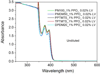
3.3.1.1 Absorption spectra of polysiloxane liquids ... 56
3.3.1.2 Absorption spectra of scintillating solutions ... 57
3.3.2 Fluorescence spectra ... 59
3.3.2.1 Fluorescence of polysiloxane liquids ... 59
3.3.2.2 Fluorescence of scintillating mixtures ... 61
3.4 Scintillation response of polysiloxane liquids ... 66
3.5 Conclusions ... 70
Chapter IV ... 73
4.1 Introduction ... 73
4.2 Experimental part ... 74
4.3 Fluorescence analysis ... 74
4.4 Fluorescence lifetime analysis ... 76
4.5 Scintillation lifetime analysis ... 79
4.6 Scintillation light yield ... 86
4.7 Pulse shape discrimination capability ... 87
4.8 Conclusions ... 92
Chapter V ... 93
Time response of polysiloxane plastic scintillators ... 93
5.1 Introduction ... 93
5.2 Experimental part ... 94
5.3 Fluorescence emission analysis ... 94
5.4 Fluorescence lifetime analysis ... 99
5.5 Time resolved ion beam luminescence (TRIBIL) ... 102
5.6 Scintillation light yield ... 107
5.7 Scintillation pulses ... 108
5.8 Conclusions ... 110
Chapter VI ... 113
Red emitting polysiloxane scintillators ... 113
6.1 Introduction ... 113
6.2 Experimental part ... 114
6.3 Fluorescence and energy transfer ... 114
6.3.1 Fluorescence emission ... 114
6.3.2 Energy transfer analysis ... 118
6.4 Scintillation light yield analysis ... 126
6.4.1 PMT measurements ... 126
6.4.2 APD measurements ... 128
6.5 Neutron response ... 132
6.6 Conclusions ... 132
Chapter VII ... 135
HYDE experiment ... 135
7.1 Introduction ... 135
7.2.1 Device structure ... 136
7.2.2 Polysiloxane deposition ... 137
7.2.3 Thermal neutron converters deposition ... 138
7.2.4 Neutron Tests ... 142
7.2.4.1 Fast neutrons ... 142
7.2.4.2 Thermal neutrons ... 142
7.3 Performances of 3D hybrid detectors ... 143
7.3.1 Fast neutrons ... 143
7.3.2 Slow neutrons ... 144
7.4 Conclusions ... 148
Conclusions and Future Perspectives ... 149
List of Abbreviations and Acronyms ... 153
References ... 155
Scientific production ... 169
HYDE and scintillators ... 169
Other activities ... 169
Proceedings... 170
LNL annual reports ... 170
Introduction
The attention of the scientific community to neutron detection has been continuously increasing for more than 60 years (Figure 1), mainly due to the broad range of applications in many fields, ranging from nuclear physics [Leo1987], to homeland security [Joyce2012], materials analysis [Vartsky2003], medicine [Kirov2005], fusion science [Kaschuck2000] and more. In the last decade in particular, the research on this topic experienced a fast growth, boosted by the increased popularity of neutron characterization techniques (neutron imaging, neutron scattering and neutron diffraction), by homeland security issues connected with terrorism threats and by the 3He shortage [CRSreport2010].
Figure 1. Annual distribution of the number of papers on "Neutron Detector" in Scopus database.
3He has been traditionally the most used material for neutron detection, especially in
achieving very good gamma rejection rates. Best performing liquid scintillators, based on xylene, have however some drawbacks connected with their high toxicity, high volatility and high flammability. The obvious solution to overcome these problems is the replacement of toxic solvents with less harmful ones, and strong efforts have been put in the development of new solutions [Chang2015, Joyce2012, OKeeffe2011, Bentoumi2013] but, despite the good results achieved, at the moment they do not seem to equal the performances of xylene based scintillators [Pawelczak2013].
Polysiloxane liquids could also play a role in this research for new, less hazardous solvent, given their very good chemical stability, excellent thermal stability, very low toxicity, low flammability, low volatility (lower than 10-4 torr at room temperature) and high flash point (more than 200°C) [GelestMSDS]. For this reason, in this work, several possible polysiloxane solvents were tested as liquid scintillators, analyzing their optical properties and their gamma rays response (Chapter III). This investigation allowed selecting 1,1,5,5-tetraphenyl-1,3,3,5-tetramethyltrisiloxane (TPTMTS) as the best performing solvent. Since one of the key characteristic of liquid scintillators is their pulse shape discrimination capability, TPTMTS based mixtures were also investigated in this sense, analyzing their time response at various concentrations of primary dye and under different type of excitation (Chapter IV).
Another possible way to overcome these problems regarding the toxicity and volatility of liquid scintillators would be the use of plastic scintillators. At present however, their use for neutron detection is mainly hindered by their very poor pulse shape discrimination performances. Many attempts have been done in the last decade to overcome this problem, as reviewed in [Bertrand2015], and recently, the first commercial plastic scintillator with PSD capability entered the market [EJ-299-33]. Many of these attempts however were not so effective or efficient, and also the commercial EJ-299-33 is still under evaluation, both as regarding its performances [Cester2014, Pozzi2013] and its long term stability.
3
steps to reach this goal is the replacement of cumbersome PMTs with more compact photodetectors. This could also allow overcoming some of the main problems of this type of device like high sensitivity to magnetic fields, large power consumption, fragility and damageability when exposed to intense light. At the moment, however, their performances in terms of gain, noise and quantum efficiency are hardly reached by other systems. This leadership is however being challenged by recent improvements in silicon based photodetectors, and Avalanche Photodiodes are very promising candidates to assume this role thanks to their very high quantum efficiency, compactness, insensitivity to magnetic fields, low power consumption, durability and good energy resolution [Holl1995, Moszynski2002, Karar1999, Schmelz1985]. One of the main factors limiting the widespread of APD detectors in coupling with scintillators is that the spectral efficiency of these devices is higher in the red part of the visible spectrum, with the maximum responsivity often above 700 nm, therefore having a non optimized spectral matching with most scintillators. Following this consideration, the shifting of the scintillator emission to longer wavelength could allow improving the spectral matching between APD responsivity and scintillator emission [Kalivas2012].
Chapter VI describes the development of red emitting polysiloxanes plastic scintillators, through the introduction of a third dye in the elastomeric matrix with the aim of improving the optical coupling with APD.
5
Chapter I
Radiation detection and scintillation
detector
1.1 Radiation-Matter Interaction
In order to understand the behaviour of any radiation detector, including scintillators, it is crucial to understand the way the radiation to be detected interacts with matter. Different kinds of radiation interact in different ways depending on their mass, charge and energy. For this reason, for an optimal detection of a specific radiation field a dedicated detector has to be used, which might not be effective in detecting a different kind of radiation. For instance, silicon based semiconductor detectors are very efficient and widely used in heavy charged particle detection, but the same detectors are generally inefficient in the detection of high energy photons or neutrons. For the purposes of this work, radiations can be divided into four main classes:
• Heavy charged particles, comprising heavy ions (e.g. alpha particles), protons, mesons.
• Electrons (e- and e+).
• Electromagnetic radiations (X-rays and γ-rays). • Neutrons.
1.1.1 Heavy charged particles
Heavy charged particles of particular importance for this work are alpha particles and protons. The former are doubly positively charged 4He ions (4He2+), widely used for detectors energy calibration, and also exploited for thermal neutron detection, since alpha particles are emitted by 10B and 7Li after neutron capture. The latter are exploited for fast neutron detection in organic scintillators, as explained more in detail later.
The energy loss of this kind of radiation depends not only on the particle, but also on the medium where this radiation travels. More in detail the specific energy loss,
− , for a particle with energy E, rest mass M (>> which is the electron rest mass), velocity V (= ) and charge , crossing a medium having , with atomic number Z, can be expressed using the Bethe formula:
− = !" # $ − %1 − "' − "( (1)
where ) is an empirical constant depending on the ionization and excitation potential of the material. This formula shows that the heavier and denser is the medium, the larger is the specific energy loss.
An important parameter connected to the specific energy loss is the range of the particle, defined as the thickness of material at which the number of particles is reduced to 50%, and represents the mean distance travelled by the particle in that medium.
A very common α source used also in this work is the one based on 241Am, that decays emitting α particles with energy of 5.486 MeV (85%), 5.443 MeV (13%) and 5.388 MeV (1%). At this energy, the range is about 3 cm in air and is as short as 44 µm in a typical polysiloxane based material. Protons of the same energy, due to their smaller mass, have a range respectively of 30 cm and 430 µm (data from SRIM simulation [SRIM]).
A consequence of the Bethe formula is that the loss of energy along the track is not constant for heavy charged particles, but it is higher at the end of their path, so that
Figure I. 1. Specific energy loss profile along the path for a 241Am α particle in polysiloxane
(spectrum achieved by SRIM simulation [SRIM]).
1.1.2 Electrons
Also high energy electrons (β-) and positrons (β+) lose their energy through excitation and ionization of the matter, but interactions occur at lower rate than with heavy charged particles. Furthermore, due to their lower mass, they lose larger energy fractions in scattering with electrons (more common) and nuclei (rarer).For this reason they don’t follow a straight track, but a tortuous path, so that observed range and real path can have different lengths (real path can be up to 4 times longer), and their track can undergo large deviations from the straight line especially after collisions with nuclei. As an example, the observed range for 1 MeV β rays in polysiloxane is about 4 mm, almost 100 times longer than alpha particles [Birks1964].
1.1.3 Photons
High energy electromagnetic radiations are classified as X-rays and γ-rays depending on their origin: X-rays are photons emitted by excited electronic orbitals of atoms, while γ-rays are emitted from atomic nuclei, as an effect of radioactive decays or nuclear reactions. The detection of high energy photons usually exploits three different mechanisms, depending on the material and on the energy of the radiation: photoelectric absorption, Compton scattering and pair production. All of them lead to complete or partial energy transfer from the photon to an electron, whose energy can be detected. Depending on the material and on the radiation energy, these processes can also occur simultaneously. The importance of the different processes as a function of energy in polysiloxanes are shown in Figure I. 2
Figure I. 2.γ-rays cross section for the different types of photon interactions as a function of energy in a polysiloxane material (data achieved from [NIST2010]).
1.1.3.1 Photoelectric effect
In the photoelectric process, the photon is absorbed by an electron in the atomic orbital of the medium. The energy of the photon is high enough to cause the ionization of the material and the ejection of the electron with energy equal to:
+,= ℎ. − +/ (2)
being ℎ. the photon energy and +/ the electron binding energy.
This electron can later cause excitation and ionization in the material, allowing the detection of the radiation. As a first approximation, the probability to have
this reason, photoelectric effect is the main process for relatively low energy photons and is much more important in elements with high atomic number. Following these considerations it is clear that in light materials, typical for organic scintillators, photoelectric effect is almost negligible if no high Z element is added [Cho1975, Bertrand2014, Hamel2011a].
1.1.3.2 Compton Effect
The Compton Effect is usually the most effective process for organic materials in the energy range between 0.1-0.5 MeV and 10 MeV that is the energy of the most used γ sources. For this reason this is the process exploited also by plastic scintillators (and polysiloxane ones among them) for the detection of γ rays, and is particularly important for this work.
During this kind of elastic process, γ-ray interacts with an electron, considered at rest, and transfers part of its energy to it. This electron recoils with a certain angle 5 with respect to the direction of the incoming photon, and with a certain energy + , while the photon scatters with a different angle 6 and an energy +′. The energies of the scattered photon and of the recoil electron depend on the scattering angle of the photon, so that:
+8=
9:< =; %9> ?' (3)
+ = + − +′ (4)
Following these equations, depending on the photon scattering angle, the energy of the recoil electron can vary between 0 and a maximum value (+ ), known as Compton Edge, that takes the value:
+ =
9:< =; (5)
Figure I. 3. Energy distribution of Compton recoil electrons for different γ energies [Evans1958].
1.1.3.3 Pair production
At energies higher than 10 MeV, the Compton scattering cross-section decreases and a third type of process becomes important. This process usually occurs in the electric field of the atomic nucleus, where the high energy photon is totally absorbed to create an electron-positron pair. In order to create this pair, a minimum energy of
2 "=1.02 D E is needed, so that this process cannot occur for γ energies
below 1.02 MeV. Over this threshold, the energy in excess is transformed into kinetic energy, so that:
+,F +G +H 2 "
Also in this case then, as in the case of the photoelectric effect, the measured energy spectrum is a single peak, with an energy corresponding to +H
1.1.4 Neutrons
Neutrons, similarly to photons, have no electric charge and for this reason they cannot experience coulombic interactions with electrons or nuclei in the material. Unlike the other types of radiation, neutrons interact only through the strong force within the nuclei, but since this force requires a very short distance (~
the interactions are much rarer than the Coulombic ones, so that they can travel several centimetres in a medium without being scattered or absorbed. As a consequence, in order to have an efficient neutron shield or an efficient neutron of Compton recoil electrons for different γ energies [Evans1958].
section decreases and a third type of process becomes important. This process usually occurs in the electric field of the atomic nucleus, where the high energy photon is totally absorbed positron pair. In order to create this pair, a minimum energy of is needed, so that this process cannot occur for γ energies below 1.02 MeV. Over this threshold, the energy in excess is transformed into kinetic
(6)
as in the case of the photoelectric effect, the measured
2 ".
to photons, have no electric charge and for this reason they cannot experience coulombic interactions with electrons or nuclei in the material. Unlike the other types of radiation, neutrons interact only through the strong force
~10>9J ),
mainly in two ways: in the first case neutrons are completely absorbed by a nucleus, causing its excitation and the consequent decay through a neutron-induced nuclear reaction, with the emission of heavy charged particles, other neutrons and, in some cases, gamma rays; the second type of interaction instead is elastic scattering between the neutron and a nucleus of the material.
The cross section of these processes has strong energy dependence, and for this reason, historically, neutrons have been classified depending on their energy into fast, epithermal, thermal and cold neutrons (Table I. 1). A wider classification divides neutrons into fast and slow neutrons with the division set around 0.5 eV, corresponding to the cadmium cut-off energy (i.e. the energy where the neutron absorption cross-section of cadmium falls abruptly). It has to be remarked that this limit and the previous classification are not univocally defined and different authors have proposed different boundaries for the two groups [Herwig2009, Knoll2000, Leo1987].
Table I. 1. Neutron classification [Herwig2009]
Neutron classification
Energy (meV)
Velocity
(m/s) λ (nm)
Cold <1 <437 >0,9
Thermal 25 2187 0,18
Epithermal 1000 13832 0,029
Fast >1000 >14832 <0,029
1.1.4.1 Slow neutrons
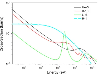
The interaction of slow neutrons with matter occurs mainly by neutron capture reactions. The cross section of these processes, excluding the effect of resonance peaks, shows a 9K dependence (being L the neutron speed), so that at low neutron energies the reactions are the most probable. The most employed elements for the detection of slow neutrons are those allowing, through the (n,α), (n,p) or (n,t) reactions, to convert neutrons into heavy charged particles that can be promptly detected with almost 100% efficiency. It is also crucial to have a high cross-section, in order to reduce the volume of the detector and increase the efficiency. This explains why 3He, 10B and 6Li are the most used elements for slow neutrons detection. These isotopes have a very high cross section (Figure I. 4) and allow a prompt neutron conversion respectively through the reactions 3He(n,p) 3H, 10B(n,α)7Li and 6Li(n,α)3H. Another isotope which is sometimes used for neutron detection is 157Gd. In this case the reaction doesn’t produce heavy charged particles, but gamma
detected, but the incredibly high cross section of this reaction, which is almost 100 times higher than the other mentioned reactions (Figure I. 4) can make it convenient in some cases.
Figure I. 4. Neutron absorption cross-sections for the most used reactions in slow neutron detection [ENDF].
1.1.4.2 Fast neutrons
Figure I. 5. Comparison between neutron elastic scattering cross section in hydrogen and the neutron absorption cross section of the most used slow neutron converter in the keV-MeV
range.
More in details, the energy of the recoil nucleus can be expressed as:
+M %N:9'" N 1%1 − OP6' (7)
where Q is the mass number of the recoil nucleus, +R is the incoming neutron energy and 6 is the scattering angle of the neutron in the centre of mass coordinate system. For 6 = S, i.e. for head-on collisions, the recoil nucleus has the maximum energy, equal to:
+M =%N:9' N 1 (8)
It follows straightforwardly that with hydrogen atoms (A=1) +M = +R, meaning that the neutron transferred all its energy to the nucleus. From these considerations it is clear that the best materials to slow down neutrons and to exploit the energy of the recoil neutrons are light hydrogen rich materials.
scintillators, for the detection of fast neutrons, as seen more in details in the next paragraphs.
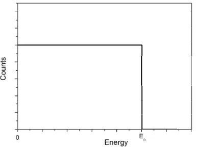
Figure I. 6. Expected energy spectrum of recoil protons produced by scattering on neutrons with energy below 10 MeV on hydrogen atoms.
1.2 Scintillation detectors
Scintillation detectors played a major role in many nuclear physics experiments, starting from the famous Rutherford experiment in 1909, when the light pulses where counted by sight [Geiger1909] up to now, in ATLAS and CMS detectors [Seiden2012] when much more advanced photodetectors are employed.
The working principle of scintillating materials is based on the emission of light pulses produced by the excitation and ionization of the material induced by ionizing radiations. These light pulses can be detected and used to achieve information about the particles originating them. At the basis of the scintillation process is the property called luminescence, which is the ability of a certain material to decay from an excited state through the emission of light.
Depending on the type of material used for this application, scintillators are classified as:
• Inorganic scintillators • Organic scintillators
o Organic scintillating crystals o Liquid scintillators o Plastic scintillators
especially in organic scintillators, to their relatively low cost (plastic and liquids) and, with the partial exception of plastic scintillators, to their capability to distinguish the type of radiation exploiting the Pulse Shape Discrimination (PSD) technique. Ideally, the characteristics that a scintillator should have are [Knoll2000]:
• High scintillation efficiency
• Linearity between particle energy and light output • High transparency, especially at the emission wavelength
• Emission wavelength matching the maximum sensitivity of the photodetector
• Fast decay time
• High manufacturability also in large volumes
• High refractive index (close to that of photodetector window) • Low cost
• Pulse shape discrimination
At present, no material possesses these properties all together and for this reason, several scintillators exist, that are optimized for different specific applications and for the detection of different types of radiation.
1.2.1 Inorganic scintillators
1.2.2 Organic scintillators
Differently from inorganic scintillators, the luminescence of organic scintillators is an intrinsic property of the molecules that constitutes the material, so that it is retained even in vapour state. Scintillation of organic materials is usually given by the emission of light following an electronic transition from the excited state to the ground state of aromatic groups that are the fundamental component of any organic scintillator. The main advantages of organic scintillators are the very fast response, with decay times usually shorter than 10 ns, the possibility to be produced easily and at reasonable prices, even in large size (for plastics and liquids), and the high hydrogen content, that allow them to be used for fast neutron detection. The control of impurities is less stringent than in inorganic crystals, but it is still very important since it is reported that the contamination of some elements, especially oxygen in liquid scintillators [Birks1964, O’Keeffe2011], can lead to quenching effects that reduce the light yield and the time performances of the scintillators. The main drawback of organic scintillators is that the scintillation light yield is usually lower than in their inorganic counterpart, and this is reflected also in a poorer energy resolution. Furthermore they proved to be less radiation hard than their inorganic counterpart, thus limiting their use where low radiation doses are present.
Depending on their physical form, organic scintillators can be mainly divided into three classes: pure crystals, plastic and liquid scintillators.
1.2.2.1 Organic crystals
Organic crystals were the first type of organic scintillators to be used, in 1947, with the discovery of naphthalene crystals [Brooks1979]. Within organic scintillators they are the materials with the highest scintillation efficiency, even if their fragility, the anisotropy that reduces the energy resolution and the difficulty to produce them in large volumes and cut them in the desired shape and size made their use uncommon. The most used organic crystals are anthracene (best light yield), stilbene (pulse shape discrimination) and naphthalene. Anthracene crystals, in particular, remain the reference standard for organic scintillators as regarding the light output.
1.2.2.2 Liquid scintillators
efficiency is too low to be exploited for scintillation. For this reason a highly efficient solute, called primary dye, is dissolved in the base, thus collecting the excitation from the solvent and emitting it with higher efficiency at longer wavelengths. Both solutes and solvents need to have aromatic groups in order to be able to emit light after radiation excitation.
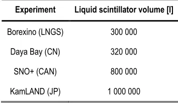
The main advantages of liquid scintillators are their fast response and the very large detection volumes that can be achieved easily and with reasonable costs so that they become the only affordable option in large scale facilities [Araki2005, Zhan2013, Kraus2006]. Furthermore, in order to detect slow neutrons, they can be easily doped with neutron absorbing materials like Gd [Beriguete2014], 6Li [Bass2013] and especially 10B [Birks1964, Swiderski2008], which is at present the most common solution. Liquid scintillators also proved to be fairly radiation hard, harder than plastic scintillators [Zorn1990], since they lack a rigid structure that could be damaged by radiations, leading to yellowing and absorption of dye emission. As mentioned above, a drawback of these scintillators is their strong sensitivity to dissolved oxygen that seems to act as a quencher both for the solvent and for the solute [Seliger1956], [Berlman1961a]. For this reason sealing and deaeration are required in order to achieve the best performances from these materials. Furthermore most efficient and therefore most used liquid scintillators (e.g. xylene and trimethylbenzene) have also some drawbacks due to toxicity, volatility and flammability of the aromatic solvents employed and these concerns become more than an issue when very large volumes of these materials are needed. Therefore, in the last decade, new solvents have been developed with low toxicity and low volatility, e.g. linear alkilbenzene (LAB) [Marrodan2009, Lombardi2013], di-isopropylnaphtalene (DIN) [Lombardi2013] or phenyl-o-xylylethane (PXE) [Marrodan2009, Back2008].
1.2.2.3 Plastic scintillators
polyvinyltoluene or polystyrene is that they are attacked by many common organic solvents such as acetone, toluene, benzene, and they can also undergo crazing, with the formation of a cracks network on the surface that affect the optical quality of the scintillator [Leo1987]. Also plastic scintillators, similarly to liquids, can be easily doped in order to improve the sensitivity to some specific kinds of radiation, the most significant cases are plastic scintillators loaded with heavy elements, mostly lead, for x-rays and γ-rays detection (especially imaging) [Hamel2011b, Koshimizu2015] and boron, lithium or gadolinium loaded scintillators for slow neutron detection [Britvich2005, Normand2002, Breukers2013, Ovechkina2009].
1.2.3 Scintillation process in organic scintillators
When a particle releases its energy in a scintillator, a fraction of this energy is used to excite the molecules of the solvent or the matrix. This excitation is then partially transferred to one or more dyes that are responsible for the emission of light. The overall process is very fast, since it occurs in few nanoseconds, but it is composed of different steps, where several competing processes can occur leading to different non-radiative de-excitation paths. For this reason, only a fraction of the initial particle energy is finally converted to light. This fraction depends on the scintillation efficiency of the material, S and is usually around 3-4% of the particle energy. Beside S, other important properties of an organic scintillator are the scintillation emission spectrum, that, in case of plastic and liquid scintillators, depends on the last emitting dye, and is important because it has to match the region of maximum efficiency of the photodetector, but has also influences on other parameters like the attenuation wavelength and the radiation resistance; another crucial property is the scintillation decay time, that depends once again on the characteristic of the dyes and affects the acquisition rate.
In order to understand more in details the working principle of a scintillator, the scintillation process can be conveniently divided into two main parts: a first part, when the particle releases its energy in excitations and ionizations, leading to the excitation of the main constituent of the scintillator (organic crystal, solvent or polymeric matrix); and a second part, when this excitation is transferred, through different steps, at the emitting dye, responsible for the final emission, through the process called fluorescence. Since organic crystals will not be part of this work, only the case of plastic and liquid scintillators will be treated from now on.
1.2.3.1 Ionization and excitation of the matter
several molecular diameters from the track, and in case the transferred energy is high enough, secondary electrons (known as δ rays) can also be ejected from the atomic orbitals inducing more ionization and excitation further from the path. In such a way, a particle leaves behind a track of excited molecules, radicals, ions, secondary electrons and fragments, whose density depends on the specific energy loss of the particle, .
Since, in plastic and liquid scintillators, exclusively the aromatic molecules in the first excited singlet state, S1, can transfer their energy to the fluorophores [King1966], only a small fraction (roughly 3-4%) of the energy released along the path will finally be converted into scintillation light, while the larger part will be used in ionization of the material, excitation of non-fluorescent species or it will be dissipated through non radiative processes like thermal de-excitation and recombination. The latter occurs especially within the track, where a high density of ions and radicals is created, and ionization quenching occurs, reducing the intensity of the emitted light by molecular collisions. This process explains the reason for the lower scintillation light yield of alpha particles in comparison to electrons of the same energy, and accounts for the non-linear behaviour of the scintillation with the radiation energy.
After being excited to higher singlet excited states, S2 or S3, the molecules of the matrix undergo a very fast vibrational relaxation process (10-11 s), called internal conversion, to the lowest singlet excited state, S1. This process has almost unitary efficiency when occurring in regions of low ionization density, while, in case of high
, it is strongly affected by ionization quenching which is acting in the same time
scale [Brooks1979, Voltz1966, Fuchs1970].
As mentioned above, in order to produce scintillation light, the molecules need to be in the S1 state. This state can be populated not only by direct excitation, but also by ions recombination or by a process called triplet annihilation [Laustriat1968], in which two excited triplet states interact to give rise to an excited and a ground singlet state, following the scheme:
T1 + T1 S1 + S0
These triplet states are mainly formed in ion-electron recombination processes, when triplet and singlet excited states are formed in a 3:1 ratio. Since the excited singlet states coming from triplet annihilation form later, their emission occurs at longer time, giving rise to a slower component in the emission, called delayed fluorescence [King1966]. Furthermore, since triplet annihilation occurs mainly due to ion recombination, which is acting in competition to the ionization quenching process, this delayed component is less sensitive to ionization quenching, and its relative intensity, in comparison to the prompt component, will be more intense the higher is
the density of ionized states, thus depending on . This consideration is at the
The relationship between the intensity of the scintillation light emitted per length unit,
U, and the specific energy loss has been studied in details by many authors. A very
popular mathematical formulation of this dependence is the one proposed by Birks [Birks1964]:
U VW;WA
9:X/ W;WA (9)
where S is the scintillation efficiency, Y is the density of ionized species,
depending on the specific energy loss, and Z is the ionization quenching parameter. An alternative formulation was proposed by Wright [Wright1953]:
U N
"/ !1 +2Y $ (10)
Finally a most complicated but most accurate relation was introduced by Voltz et al. [Voltz1966], dividing the contribution to the scintillation intensity in two components, respectively due to the prompt and the delayed emission. This relation seems to fit in a better way the experimental data also for heavy charged particles [Brooks1979]. In the limit of small instead, they all reduce to the linear relation:
U= [ (11)
that has been experimentally verified for fast electrons.
1.2.3.2 Energy transfer
After reaching the first excited singlet state, S1, the molecule of the solvent (solid or liquid) can undergo some different processes in order to return to the ground state S0. This de-excitation can occur either radiatively, with the emission of a photon, or non-radiatively. In the first case, the photon can be absorbed by another solvent or matrix molecule, in the so called radiative energy migration process; in particular, if it is absorbed by a primary dye molecule, the process is called radiative energy transfer. Non-radiative decay, instead, can occur by non-radiative energy migration to another base molecule, by non-radiative energy transfer to a primary dye molecule or by quenching and thermal de-excitation.
The energy transfer process in particular is very important, since it is the one allowing the excitation of the dye through the matrix aromatic groups. Indicating X as the matrix or the solvent fluorophore, Y as the primary dye and Z as the secondary dye, the energy transfer process from X to Y can be schematized in the following way:
where S0X and S1X represent respectively the ground and excited singlet state of the solvent, and S0Y and S1Y are those of the primary dye. In an efficient plastic or liquid scintillator, this process is strongly competing with other de-excitation processes. Especially non-radiative energy transfer is particularly important in the scintillation process, since it is faster and more efficient than the radiative energy transfer, involving the emission and re-absorption of photons and since it allows in some cases also the transfer of triplet excitation energy [Kaschke1988]. The rate of non-radiative transfer increases with the amount of dye and for this reason, in liquid or plastic scintillators, where high primary dye concentrations are typically employed, this mechanism becomes the leading one for the transfer of the solvent or matrix excitation energy. At lower dyes concentrations, instead, the dominant process is the radiative one, since the average molecule distance becomes larger than 3-10 nm usually required for an efficient non-radiative interaction [Lakowicz2006].
From several studies performed on liquid and plastic scintillators, it appears that the energy transfer from solvent or matrix to primary dyes occurs mainly by non-radiative processes, through long range dipole-dipole interactions [Birks1964] between molecules with similar energy levels, and thereafter also called resonance energy transfer.
This mechanism has been studied by Förster [Forster1959], so that it is also known as Förster energy transfer. Following his formulation, the energy transfer rate of this process follows the equation:
Z_=`9
a!
M b$
c
(12)
where de is the donor lifetime in absence of acceptor, f is the donor-acceptor distance and g is the so called Förster radius, representing the donor-acceptor separation at which transfer rate and decay rate (= 9
`a) are equal.
The Förster radius can be calculated as:
gc=h %ij9 'k la
9"m 4noR p )e%q'rN
s %q'q tq (13)
where u" is an orientation factor and assumes the value of "J in case of randomly
distributed freely rotating molecules and the value of 0.476 in case of rigid media where the molecules rotation is slower than the de-excitation rate [Valeur2001]. NA is the Avogadro’s number, is the refractive index of the medium in the wavelengths region of interest, Φe is the donor quantum yield in the absence of transfer, and the last term represent the overlap integral between donor emission (normalized to
p )s e%q' tq = 1) and acceptor molar absorption coefficient (rN). From this
spectrum very well overlapping with the matrix or solvent emission spectrum, together with high quantum efficiency. From Eq.12, it also follows that the transfer rate is inversely proportional to the sixth power of the intermolecular distance between donor and acceptor. This means that this kind of process is much more efficient at high concentrations, when this distance is small, so explaining why the primary dye is usually dissolved in the matrix with concentrations in the order of 1% wt. If the process involves excited triplet states, the transfer mechanism is slightly different: in this case, the only dipole-dipole interaction is not sufficient and the transfer occurs by electron exchange mechanism, occurring at shorter distances since it needs a certain degree of orbital overlap [Forster1959, Valeur2001]. In case of binary systems, the energy transfer from the base to the primary dye is mainly non-radiative, due to the high concentration of the latter. This is especially true in liquid scintillators, where the molecular diffusion contributes to bring the excitation close to the acceptor molecule [Birks1970a], while a certain amount of non-radiative one cannot be excluded in plastic scintillators [Hallam1978]. In any case, after the excitation is transferred to the primary dye, light is emitted through radiative decay by the latter. In case of ternary systems, a further step is required in order to transfer the excitation to the secondary dye. Since this secondary solute is dissolved in the system at much lower concentration, the intermolecular distance between the two dyes is not small enough to allow complete non radiative transfer, and the process partially occurs also via radiative transfer, through the emission of a photon from the primary dye, and its re-absorption by the secondary one [Birks1964, Birks1970a]. At the end of this process the light emission occurs almost entirely from the secondary dye, by radiative de-excitation.
The energy transfer efficiency from primary to secondary dye and especially from matrix or solvent to primary dye is favored by another process, called energy migration. It can occur both radiatively and non-radiatively, but in plastic or liquid scintillators, the latter, appears to be the dominant one. This process seems to be driven by short range exchange interactions between adjacent aromatic groups both in liquids and in plastics [Zhang1995, Horrocks1974, Hirayama1968, Mathad1986, Birks1966].
In liquid scintillators, the energy migration is further facilitated also by thermal diffusion of excited molecules that contributes, together with non-radiative processes, to bring the solvent excitation close to the acceptor molecule.
1.2.4 Luminescence of organic molecules
1.2.4.1 Excited state
As already mentioned, the property at the basis of the scintillation capability of a certain material is the luminescence, which is the ability to decay from electronic excited states through emission of photons.
Excitation can be induced by several different processes (chemically, mechanically, thermally, electrically,…), but in case of scintillation, the most important processes are photoluminescence, induced by the absorption of photons, and radioluminescence, that is at the base of scintillation and in which the excitation is induced by ionizing radiations.
In case of atomic transitions, since the mass of the nucleus is several orders of magnitude larger than that of the electron, electronic transitions are much faster than the consequent rearrangement of the nuclei, which can thus be considered in a fixed position during the excitation (Franck-Condon principle). After the transition has occurred, the new electronic configuration changes the electric field felt by the nucleus, that begins to oscillate around a new equilibrium position. For this reason, electronic excited states can be divided into different vibrational sublevels having slightly different energies one from each other. Since at the end of the excitation process, the nucleus is not yet in the new equilibrium position, the electronic transition occurs at higher vibrational sublevels. After the transition, the system dissipates the excess energy, bringing the excited electron to lower vibrational sublevels. This non-radiative relaxation is called internal conversion. In case of luminescent species, the system cannot completely dissipate the excess energy in a vibrational way, but once the lowest sublevel of the excited state has been reached, the return to the ground state occurs radiatively with the emission of a photon, in a much longer time than the excitation or than the internal conversion. Similarly to the excitation, also the decay follows the Franck-Condon principle, so that, after coming back to the ground state, further vibrational relaxation is needed to reach the lowest vibrational sublevel of the fundamental state (Figure I. 7).
Figure I. 7. Franck-Condon diagram for an electronic transition showing the difference in energy between excitation and de-excitation.
In organic compounds, luminescence is associated to the presence of conjugated molecules, especially aromatics. The presence of unsaturated bonds (with hybridization), allows the electrons to occupy π orbitals. If more π orbitals are present next one each other, they form a delocalized system whose excited state is responsible for luminescence (π π* transition).
1.2.4.2 Radiative decay
Luminescence can be divided into two main radiative processes: fluorescence and phosphorescence. The former is the decay from an excited singlet state (S ground singlet state (S0), S1 S0, where the electron in the excited state and its counterpart in the ground state have antiparallel spin. This is an allowed transition and therefore it occurs efficiently and quickly (10-8 to 10-9 s) with the emission of a photon.
Phosphorescence instead is the decay from an excited triplet state (T1
singlet state (S0). The triplet state T1 has slightly smaller energy than the corresponding singlet state S1, and is characterized by excited and ground state electrons having parallel spin. Triplet states can be populated by ion recombination, Condon diagram for an electronic transition showing the difference in energy
In organic compounds, luminescence is associated to the presence of conjugated matics. The presence of unsaturated bonds (with sp or sp2 ), allows the electrons to occupy π orbitals. If more π orbitals are present next one each other, they form a delocalized system whose excited state is
Luminescence can be divided into two main radiative processes: fluorescence and phosphorescence. The former is the decay from an excited singlet state (S1) to a excited state and its counterpart in the ground state have antiparallel spin. This is an allowed transition s) with the emission of a
as explained in the previous section (1.2.4.1)or from the excited singlet state, by a non radiative process called inter-system crossing. The transition T1 S0 is forbidden by selection rules and the emission of photons occurs then slowly (10-3-1 s) and less efficiently.
There is also a third kind of radiative emission, called delayed fluorescence and already mentioned earlier. In this process, lasting for a period of 10-7-10-3 s, the decay from the excited triplet state to the ground singlet state doesn’t occur directly, but through the interaction with another molecule in the same excited triplet state. The result of this interaction is the formation of an excited and a ground singlet state, T1 + T1 S1 + S0. S1 decays by fluorescence but, due to time needed for the triplet state interaction to occur, the photon is emitted at delayed times.
The most important parameters needed to characterize a fluorescent molecule are the lifetime (τ) and the quantum efficiency (q).The former describes the time evolution of the intensity of the light emitted by the fluorophore, and usually follows an exponential decay.
)%w' = ) >xy (14)
If the emission is the sum of different component, or in case also delayed fluorescence occurs, the decay can be multi-exponential, presenting two or more different decay time constants.
)%w' =Q >yzx + Y >yx (15)
The quantum efficiency instead is the ratio between the emitted photons and the absorbed ones, and can be expressed as:
{ = X|
X|: X1} (16)
where kfis the radiative emission rate and knr is the non radiative one that can be due to phenomena like quenching, inter-system crossing or energy transfer.
1.3 Neutron detection
The most important characteristics for a neutron detector are: high efficiency, good time resolution, efficient neutron/gamma discrimination, good neutron energy resolution and good pulse height resolution [Harvey1979]. No neutron detector can however fulfil all these requirements at once, and for this reason, different applications requires different detectors, depending on the specific need (e.g. neutron counting, neutron spectroscopy, neutron imaging), on the neutron energy range (fast or slow) and on the specific conditions (high gamma background, required volume, ...).
Fast neutron detection generally occurs in three different possible ways. A first technique is to exploit neutron moderation, using water, heavy water, paraffin or polyethylene, in order to slow neutrons down to thermal energies and detect them using neutron induced nuclear reactions, as seen in the previous paragraph. This is the case of one of the most used neutron detector, called Bonner Sphere. A second possible strategy is to exploit neutron induced reactions that have a relatively high cross section to the desired energies, similarly to what has been seen for slow neutrons. At these higher energies however the cross section is usually much lower than for slow neutrons. Typical exploited reactions are 3He(n,p)3H and 6Li(n,α)3H that show a resonance peak in the MeV range. A third type of detector, which is probably the most common one in this field, directly detects the recoil nuclei produced in the elastic interactions. This technique has the advantage that the energy of the recoil nuclei is somehow dependent from the neutron energy, and thus it allows to perform neutron energy spectroscopy, not possible in the other types of detector.
Table I. 2. Main characteristics of most used slow neutron absorbers.
Converter σ (25 meV)
[barns] Reaction products Q-value
3He 5353 H (0.573 MeV), α (0.191 MeV) 0.764 MeV
10B 3870 α (1.47 MeV), 7Li (0.84 MeV) α (1.78 MeV), 7Li (1.01 MeV)
2.31 MeV (94%) 2.79 MeV (6%)
6Li 945 α (2.05 MeV), 3H (2.73 MeV) 4.78 MeV
157Gd 256000 Several products with
energies below 100 keV -
As regarding thermal neutron detection, it usually relies on the neutron capture reaction described above. The neutron converter and the reaction products however can be detected in several different ways depending on the application. The main types of slow neutron detectors are gas detectors, scintillator detectors and solid state detectors. Gas detectors can be filled by a neutron converting gas (3He or enriched BF3). The products of the neuron capture reaction ionize the gas itself, and the so formed ions are accelerated causing further ionization before being collected at the electrodes. A slightly different version of gas detectors is represented by boron lined counters, where the neutron conversion is not performed by the gas, but by a thin layer of enriched boron deposited on the wall of the gas container. The reaction products of the boron capture reaction are responsible for the gas ionization that is collected by the electrodes in the same way as before [Knoll2000].
deposited over a microstructured solid state detector, that allows to detect the reaction products coming from the converter [Herwig2009, McGregor2009, Mendicino2014]. Finally, thermal neutron detection can also be efficiently fulfilled by scintillators, as treated below.
1.3.1 Scintillators for neutron detection
Table I. 3. Main properties of EJ-301 and EJ-309 liquid scintillators and EJ-299-33 plastic scintillators, all of them with PSD capability.
Organic scintillators are widely used as neutron detectors because of their versatility and their suitability to produce large detectors volumes, relatively easily and at reasonable prices. Organic liquid and plastic scintillators are mostly composed by hydrogen and carbon atoms and for this reason they are able to detect fast neutrons, exploiting the neutron recoil reaction. So far, the most employed materials in this field have been organic liquid scintillators, because the possibility to easily produce very large scintillator volumes allows for good detection efficiency that would not be achievable with organic crystals like stilbene or anthracene. But most of all, the success of liquid scintillators is due to their capability to perform pulse shape discrimination (PSD), which is a key aspect for neutron detection since it allows to
Properties EJ-301 EJ-309 EJ-299-33
Type of scintillator PSD liquid PSD Liquid
Low Toxicity PSD plastic Light Output [%
anthracene] 78 75 56
Photon yield [ph/MeVee] 12000 11500 8600
λem [nm] 425 424 420
H atoms [1022 cm-3] 4.8 4.37 5.13
C atoms [1022 cm-3] 4.0 5.46 4.86
Electrons [1023 cm-3] 2.3 3.17 3.55
Density [g/cm3] 0.874 0.964 1.08
Fast Decay Time [ns] 3.2 3.5 5
Long Decay Times [ns] 32.3; 270 n. a. 140; 150
distinguish neutrons from the gamma background [Brooks1979]. In this respect, the best liquid scintillators, and still the most used is the xylene based EJ-301 (or its equivalent BC-501A or NE-213). These liquids have the drawback of toxicity, flammability and volatility, requiring sealing and consequently reducing the handiness of the system. To overcome this issue, non toxic solvents were tested [Chang2015, Joyce2012, OKeeffe2011, Bentoumi2013], and a new low toxicity, low volatility liquid scintillator with PSD capability entered recently the market [EJ-309ds] (Table I. 3).
The ultimate solution to these problems however would be the replacement of liquid scintillators with plastic scintillators having the same performances. This would allow detecting fast neutrons in an easier way, also combining in the same device charged particles detection.
For this reason, recently, strong efforts have been put in the development of plastic scintillators capable of PSD [Bertrand2015, Zaitseva2012], but the suitability and stability of these new products is still under investigation [Cester2014] and for this reason, at the moment, plastic scintillators are employed as fast neutron detection only in the few cases when gamma discrimination is not a concern because of relatively low background or because other discrimination techniques, e.g. time of flight (ToF), can be applied [Agosteo2016]. In order to produce PSD plastics, different strategies have been employed so far: composite scintillators, addition of triplet harvesting materials and increase of the triplet-triplet interaction.
The first method consists of inserting organic crystal, capable of PSD in transparent inert matrix [Tarasenko2013], with the drawback of low scintillation light output due to light scattering by crystals. The second smart method consists of the addition to the organic matrix of triplet harvesting dyes, emitting at different wavelength and with a longer lifetime, allowing a combination of spectral discrimination and pulse shape discrimination [Feng2012], but with the drawback of a much longer time response, in the order of µs, typical of triplet harvesting organometallic compounds.
Finally, the most used technique so far employed to enhance PSD capability of plastic scintillation has been the strong increase of the primary dye concentration, in order to favor the dye molecules interaction and in turn increase the triplet-triplet interaction probability. The first attempt was reported by Brooks in 1960 [Brooks1960], and other followed until very recently [Zaitseva2012, VanLoef2014]. Even if his technique seems to be the most promising and it also brought to the commercialization of EJ-299-33 plastic scintillator, the performances reached so far are still lower than liquids [Cester2014, Pozzi2013], and the scintillators seems to have problems related to the long term stability of the high dye concentrations (up to 30 wt%) dissolved in the matrix [Bertrand2015].
[454ds] or EJ-254 [EJ-254ds] or liquid scintillators doped with Gd [EJ-331ds, BC-521ds] or 10B (EJ-339A, BC-523A). The main issue in this case is to find the most suitable compound in order to achieve the highest solubility without affecting the performances. In case of boron containing mixtures, the most used molecules are carboranes [Pawelczak 2014], boric acid [Britvich2001] and other metallorganic compounds [Bollinger1957]. In case of lithium, Li-methacrylate [Breukers2013], lithium salts [Bass2013] and more complex metallorganic compounds [Zaitseva2013] have been successfully employed. Finally, gadolinium has been incorporated in organic systems, by using different aromatic and non-aromatic metallorganic complexes [Ovechina2009, Bariguete2014]. All these systems have some advantages and disadvantages. Boron is at the moment the most used solution because it has a quite high abundance of 10B in the natural mixture and thus, in most cases, enrichment is not needed, with great cost saving. It is also a well known and documented element, and the high cross-section allows achieving very good efficiencies. On the other side, the energy released by the reaction products is not so high in comparison to other possible elements. Furthermore, enrichment is not so easy, and in case enriched boron is needed the price of the system is strongly increasing. Finally, some problems have been encountered with the toxicity of boron compounds and also with their volatility that is reducing the long term stability of the scintillator. Lithium instead has the advantage of a higher energy produced during the neutron capture reaction, increasing the scintillation light yield and also allowing for a better pulse height discrimination. From the chemical point of view, Li compounds are easier to produce, but despite these advantages, the hygroscopicity of most Li compounds and most of all, the lower cross-section are intrinsic limits of this element, hindering its diffusion. Finally, gadolinium is one of the elements with the highest thermal neutron cross-section. Unfortunately, the doping of organic materials with Gd complexes is not straightforward. Furthermore, its reaction products are mainly low energy x-rays and γ-rays that due to their long range can also escape from the material without being detected, cannot be easily distinguished from the background, and doesn’t allow good neutron-gamma discrimination. The main advantage of organic scintillator in the field of thermal neutron detectors is represented by their fast response, which is in some cases orders of magnitude faster than other scintillators. In terms of efficiency and scintillation light output, instead, their performances are lower than inorganic scintillators, which are, at the moment, the most common scintillating system. In this field, in the last years, there have been a large number of newly developed crystals, based on Li, B, Gd or a combination of them. Not all of them entered the marked, but some of them proved to be very interesting materials.
having the highest light output, but being limited to thin slabs due to low transparency.
In the last decade, a new class of compounds have been developed, with very interesting properties. This class of materials, called elpasolites, has composition A2LiMX6:Ce, (A=Cs, Rb, M=Y, La, Sc, X=Br, Cl, I) (see [Van_Eijk2012] and references therein), and has been developed after the discovery of the interesting properties of Cs26LiYCl6:Ce (CLYC) scintillators. Are part of this class Cs26LiYBr6:Ce (CLYB), Cs26LiLaCl6:Ce (CLLC), Cs26LiLaBr6:Ce (CLLB), all of them showing very high light output, but also having the drawback of strong hygroscopicity.
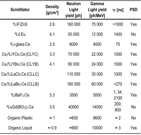
Table I. 4. Comparison between the most used inorganic scintillators for thermal neutron detection. Properties of boron doped plastics and liquids are also reported.
Scintillator Density
[g/cm3]
Neutron Light yield [ph]
Gamma Light yield
[ph/MeV]
τF [ns] PSD
6LiF/ZnS 2.6 160 000 75 000 >1000 Yes
6LiI:Eu 4.1 50 000 12 000 1400 No
6Li-glass:Ce 2.5 6000 4000 75 Yes
Cs26LiYCl6:Ce (CLYC) 3.3 70 000 22 000 1000 Yes
Cs26LiYBr6:Ce (CLYB) 4.1 90 000 24 000 1000 Yes
Cs26LiLaCl6:Ce (CLLC) 110 000 35 000 1000 Yes
Cs26LiLaBr6:Ce (CLLB) 180 000 60 000 >270 Yes
6LiBaF3:Ce 5.3 3500 5000 1; 34;
2100 Yes
6Li6Gd(BO3)3:Ce 3.5 40000 14000 200;
800 No
Organic Plastic ≈ 1 ≈650 8600 ≈ 2 No
Chapter II
Materials and methods
2.1 Polysiloxanes
The scintillators produced and studied in this work, liquid or plastic, are made by materials belonging to the category of polysiloxanes, commonly known also as silicones. These polymers are composed by a main backbone, formed by silicon and oxygen atoms, regularly alternated, and by organic substituents, attached to the silicon atoms of the main chain. Many of the optical and chemical properties of the material depend on the type and distribution of these substituents. Furthermore, in case of rigid polysiloxane, is the reaction between side groups that allows the formation of intermolecular bonds (cross-linking) conferring to the polysiloxane, mechanical properties typical of elastomeric materials.
2.1.1 Properties of polysiloxanes
![Figure I. 3. Energy distribution of Compton recoil electrons for different γ energies [Evans1958].of Compton recoil electrons for different γ energies [Evans1958]](https://thumb-us.123doks.com/thumbv2/123dok_us/534054.2053213/21.420.142.282.49.231/distribution-electrons-different-energies-compton-electrons-different-energies.webp)
![Table I. 1. Neutron classification [Herwig2009]](https://thumb-us.123doks.com/thumbv2/123dok_us/534054.2053213/22.420.114.304.231.337/table-i-neutron-classification-herwig.webp)