COMMISSION INTERNATIONALE DES IRRIGATIONS ET DU DRAINAGE
INTERNATIONAL COMMISSION ON IRRIGATION AND
DRAINAGE
SEPTIEME CONGRES R. 17
SEVENTH CONGRESS QUESTION 24
AUTOMATIC MECHANICAL IRRIGATION GATES*
ALLAN S. HUMPEERYSt
SUMMARY
Small automatic irrigation gates for farm distribution systems are being developed to improve the efficiency of water use and to save labour. Two general classes of gates are described : (I) fully automatic gates which operate from the energy of water flowing in the ditch and which require a minimum of attention from the operator ; and (2) semi-automatic gates which require resetting or moving at each irrigation. The structures are designed to divert water for a predetermined period of time from a farm distribution ditch onto one portion of a field after another in sequence. They are normally used in pairs.
One structure of a pair isa sinking float border turnout gate. The float attached to the gate has a water inlet at the bottom and an air escape at the top. It sinks at a rate controlled by the amount of air escaping which, in turn, is controlled by varying the diameter and length of a small stainless steel tube. The time required for the float to lose buoyancy determines the time of gate closing, and thus the length of irrigation.
Two types of gates are being tested as companion structures to the sinking float outlet gate. One is a counterbalanced center-of-pressure check gate. This gate uses hydrostatic pressure distribution and the resultant center-of-pressure force for tripping. It opens automatically when the up-stream water level reaches a certain depth and thus may be used at any
* Vannes d'irrigation as commande automatique
Contribution from the Northwest Branch, Soil and Water Conservation Research Division, Agricultural Research Service, USDA, id:1010 Agricultural Experiment Station co-operating.
24.257
consiste en une vanne-clapet a contrepoids associee avec une vanne rabat-tante. La vanne rabattantte est munie de charnieres a sa partie superieure ;
verrouillee en position ouverte elle est suspendue au-dessues du fosse, (lever-rouillee elk tombe sous son propre poids et arrete l'ecoulement de l'eau. Elie dolt etre réajustee ma.nuellement.
Ideally, mechanization or automation of surface irrigation refers to the use of mechanical gates or farm structures and other devices that auto-matically meter water onto an agricultural field in the proper amount and at the proper time to satisfy the demands of a growing crop. This is
accomplished using furrow, border, or other existing methods of surface irrigation with a minimum of attention from the farm operator, The gates considered in this paper are small structures used in farm distribution systems and field channels as contrasted to. large structures used in canal systems. Mechanical irrigation gates may be classified as fully automatic or semi-automatic, depending upon their method of operation. A fully
automatic system operates without attention from the operator other than periodic inspections from one irrigation to the next. The need for irriga-tion and often the irrigairriga-tion time periods, however, are still largely deter-mined by the irrigator who usually has to turn water into the system. A semi-automatic system uses gates which normally require a mechanical timer such as an alarm clock or an electric device to trip the structure at a present
time('). In addition to determining the need for irrigation and its duration, the irrigator also manually resets the structures or moves them from one location to another or both prior to each irrigation. Most mechanical gates operate either from the energy provided by water flowing in the stream channel, by an electrical or hydraulic power source, or from that provided by the farm operator when the structures are reset.
One of the prime reasons for using automatic irrigation gates is to increase the efficiency c f agricultural workers. The irrigators' productivity may be increased by reducing the labour requirement and eliminating many routine tasks associated with present irrigation practice. Financial returns
to a farm operator are greater if his time and energy are spent in managing
and making operational decisions rather than in routine time-consuming chores, such as directing water around a field with a shovel, or setting
siphon tubes. One cannot, of course, relinquish the task of irrigating to perform other operations unless a satisfactory means, such as mechanization, is available for obtaining an efficient irrigation.
Irrigation mechanization not only results in higher worker pro-ductivity, but often in better water control. Using improved structures and devices, along with adequate field preparation, can result in more efficient water use. The design of an ideal mechanized system incorporates present-day concepts of crop water requirements, soil moisture holding capacities, and intake rates, Using this information, the design will allow only the amount of water necessary to supply plant needs an dany soil leach-ing requirements to be applied to the field. Thus water conservation is a potential by-product of improving irrigation procedures.
Border and basin irrigation systems are particularly well suited for automation. Furrow and corrugation systems are much more difficult to automate. Obtaining uniform water distribution to all furrows is a problem.
24.254
The'experimental automatic gates described in this paper are particularly well suited for border and basin methods of irrigation and where the water is relatively free from floating trash. They are also well suited for use in furrow systems if a means is provided to obtain uniform water distribution to all furrows, such as the use of spites or furrow tubes. Although the structures described are shown being used in an unlined ditch, they may also be used in a lined ditch.
A requirement of all automatic irrigation systems . s that the water and ditches be kept weed-free. This is especially important in this type system where a farm operator is not in attendance. The design of any automatic system should include a weed-screening device.
AUTOMATIC GATE DESIGNS CENTER-OF-PR E SSUR E GATE
Tests were conducted in the laboratory to develop an automatic gate using the principle of hydrostatic pressure distribution and the resultant center-of-pressure force for tripping. This gate, shown in Figure 1, has a horizontal pivotal axis located above the bottom of the opening a distance of approximately 0.32 times the desired water depth at which the gate will open. The model shown is 75.5 cm long by 51 cm high and is made from 1.52-mm-thick (16-gauge) galvanized steel. When the water level on the upstream side of the gate rises to a height such that the resultant force from the water pressure is above the axis, the gate opens automatically.
With a counterbalance provided to return the gate to its closed position, the gate becomes fully automatic and is well adapted for use as a com-panion structure to other gates which create a small rise in the water surface needed for tripping. Without a counterweight, the pressure gate is sometimes used as a safety structure to release water from a channel or reservoir to protect them from overtopping when the water level becomes too high. Several different counterbalancing methods were tested ; the most simple and practical is that shown in Figure 1 in which a solid metal bar is placed at the bottom edge of the gate. Although this method is preferred, thed esign is rigid and the desired water level at gate opening must be predetermined. This limitation, however, is not serious since a depth range in which the gate may open will generally be known when design-ing an irrigation system.
However, to provide flexibility in adjusting the water depth at which the gate opens, the solid bar was removed and the gate fitted with a constant-force spring counterbalance. To decrease the water depth required, the spring was mounted as shown in Figure 2. The linkage is adjusted so that the spring applies an opening force to the gate when the gate is com-pletely closed. Therefore, less water depth is required to open the gate. To increase the water tripping depth, the spring is mounted so that a closing force is applied to the gate in its closed position. The water depth on the upstream side must increase to overcome this extra force before the gate will open. With these adaptations, the water tripping depth was adjusted through a range of about 6 cm. With the gate completely open,
the constant-force spring provides the restoring force to close it.
24.255
ditch to drain between irrigations. When water 'is first turned into the ditch, water pressure against the lower portion of the gate closes it completely, The gate is sealed against leakage by a butyl rubber strip attached to the frame above the pivotal axis and to the gate below the axis.
In operation, the gate remains open as long as water flows over it. When water is turned from the ditch, or an upstream gate closes, the gate automatically returns to its normally closed position. Stiffening flanges on the rear side have a dual purpose : (1) they strengthen the gate, and (2) cause a suction to develop beneath the gate as the water level in the ditch recedes. This holds the gate open at low flows, as shown in Figure 3, and allows the ditch to partially drain before the gate closes. These gates may be adapted to existing structures, or made portable by mounting them in a frame which is then attached to the structure.
SINKING FLOAT BORDER GATES
A sinking float border turnout gate designed for use with other companion structures such as the center-of-pressure gate described above is shown in Figure 4. It is similar to a Tainter gate with a float mounted on the front portion. The float chamber is provided with a water inlet at the bottom and a controlled air escape at the top. The float sinks at a rate controlled by the amount of air escaping. In operation, the float initially is buoyant and opens the gate when water is received in the ditch immediately upstream. The gate is counterbalanced such that the buoyant force from the float is sufficient to hold it open during irrigation. Irrigation is terminated when the float Icses buoyancy and sinks, thus closing the gate.
Two methods of counterbalancing the gate are being evaluated. On small gates
a
counterweight extending behind the gate axis may be used. This is often impractical on larger gates, however, since a large weight supported some distance from the structure tends to overturn it. The counterweight may be eliminated on bath sizes by using a constant-force spring which has a constant force independent of its extension. This spring is inexpensive and easy to mount.The rate at which water is allowed to enter the float is controlled by varying the size and length of a stainless steel hypodermic needle on the air escape tube. Laboratory tests show that the time required for the float to sink may be controlled more consistently with a short length of small-diameter stainless steel tubing than with a needle valve. For the same cross-sectional area, the wall-to-wall distance is greater in the small tube than in the valve ; therefore, it is not as easily plugged. A needle lock adaptor is used at the end of the air escape tube so that the needles may be quickly replaced or interchanged with another size. Disposable sterilized needles have proved more satisfactory than the conventional reusable type. These are also provided with a removable plastic protective cover. When the
reusable needles were used, a small, clear plastic bottle was placed over them for protection.
'24 256
The sinking float gate has also been constructed with parallel arms (Figure 4) instead of the radial gate design. This offers certain advantages
since the gate opening and closing is more in a vertical direction and the float construction is simplified. Also, a closing moment is available to assist in closing the gate against friction of the rubber seals along the sides. It also has disadvantages. The extra locations where movement occurs cause greater friction, and when the gate is fully open an opening movement tends to retard its closing. Both types of gates are being evaluated in the laboratory and in the field.
FLOAT-OPERATED CHECK GATE
Another fully automatic check gate was developed for use as a com-panion structure to the sinking float border gate. This is a float-operated check gate hinged at the top with a latch mounted on the rear side, as shown in Figure 5. A movable concrete counterweight mounted on top of the gate serves two purposes. When the gate opens, it shifts to an upstream position and acts to counterbalance the gate. When water is turned from the ditch after irrigation, the gate closes automatically and returns to its normally closed, position as the water level recedes. When it is just about closed, the counterweight shifts to its rear, or downstream position and provides a small impact force to relatch the gate. This gate is less affected by trash in the water than the center-of-pressure gate.
DROP GATE
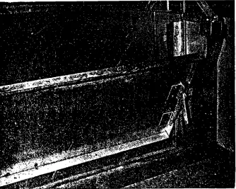
This is a top-hinged gate which is suspended over the top of the ditch in the open position, Figure 6. When released, it falls by its own weight and stops the flow of water in the ditch. It may be mounted and tripped in a variety of ways and has been used by farmers in the U.S.A. and New Zealand( 2) for several years. When used in an unlined ditch, it is usually mounted on a concrete or metal cutoff wall.
AUTOMATIC IRRIGATION SYSTEMS
BORDER SYSTEMS
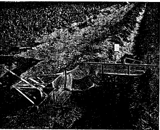
Sinking float gates and check gates were installed in pairs for field testing. The check gates were placed in the supply ditch, while the sink-ing float gates were installed at the border turnouts. In this type of installation, the paired gates are fully automatic and operate from the energy of water flowing in the ditch. Some of the border turnout gates
were mounted in a commercial precast concrete headwall to test them for adaptation to existing structures. They were installed in slots normally provided for checkboards. Others were constructed with a sheet metal cutoff wall as part of the complete gate.
24.256(a)
24.256(b)
FIGURE 2 : Counterbalance spring mounted to decrease the water depth
24.256(c)
Fttittru: 3 : Photograph showing how the pressure gate is held open by
24.256(d)
24,256(e)
24.256(f)
24.256(g)
24.256(h)
2
5 256(i)
24.256(i)
FIGURE 9 : A float-operated check gate being used with the border
24.257
closes rapidly. When the border gate closes, the water level in the ditch rises until the pressure gate opens as shown in Figure 8. Water is thus allowed to flow to the next pair of structures downstream where the
sequence is repeated. The check gate remains open as long as water flows in the head ditch. When water is turned from the ditch after field irrigation is completed, the check gate returns to its closed position ready
for the next irrigation.
A float-operated check gate is shown with the border gate in Figure 9. The general operation of this pair of gates is similar to that described above. When the border gate closes, the water level rises until water spills through the notch and into the float well of the check structure. The float well fills rapidly and the gate trips. When the gate opens, the movable counterweight shifts into its forward, or upstream position where it almost balances the gate, Figure 10. The remaining force required to
hold the gate open is provided by momentum of the flowing water against the bottom of the gate. For installations in which the velocity is very low, a small float may be required near the bottom of the gate on the up-stream side. When water is turned from the ditch after irrigation, the gate returns to its closed position. It is automatically reset when the counterweight shifts position. When water drains from the ditch, the float on the border gate and the float well on the check gate both drain. Thus, both gates are automatically reset and ready for the next irrigation without attention from the farm operator.
The gates desCribed above were field tested for approximately two weeks at the end of the irrigation season during 1967. The gates were cycled each day during this initial testing period. When the needles used for controlling the length of irrigation on the border turnout gates were protected with covers, the time periods were consistent from one irrigation to the next. Additional laboratory tests are needed to calibrate the sinking float gates to obtain the desired irrigation period in the field. With the needles protected, preliminary data indicate that time periods up to four or five hours may be reproduced in the field. Time periods of this duration will be adequate in most cases, since these gates are intended primarily for use in border systems in which long periods of time wilt generally not be needed.
Care must be taken during structure installation to obtain good compaction of the backfill to prevent piping and water seeping around the headwall. Normally the bottom of the opening of the border turnout gate is installed flush with the bottom of the ditch channel. The water velocity through the gate is sufLieat to flush sediment through the opening so that siltation does not occur. Head loss through the sinking 11 )at gate depends
upon the downstream or tailwater level. It is small when the tailwater level is high. This is desirable, since, with a high tailwater. it is often necessary to conserve head. When the tailwater level is low, the gate opening is smaller and the resulting head loss is greater. Thus. the amount of head loss through the structure adjusts itself to existing conditions and is large only when the available head is large. For those installations having a low tailwater_ level, or
where the flow leaves the gate at a high velocity, some protection may be required to prevent excessive erosion downstream from the turnout. The check gates in the supply ditch are normally installed with the crest or
24.258
is necessary to provide sufficient contact area around the opening for rubber seals. Also, it may be necessary to place a small amount of gravel down-stream from the float-operated check since a small silt bar tends to form here while the gate is open.
SAFETY STRUCTURES
Many automatic irrigation systems will require safety structures of some sort to admit water into a waste channel in the event some part cf the system Nis. the ceater-of-pressure gate is well suited for this use and as a safety structure to release water from canals or laterals, reservoirs, or recirculating-system holding ponds when the water level becomes too high. It may be used either with or without the counterbalancing feature. If it is used without :a counterbalance or spring return, it must be manually reset after opening. When used for this purpose, it should be checked periodically to make certain that it remains free and able to operate in case of an emergency.
MISCELLANEOUS
The center-of-pressure check gate may also be used in water-spreading systems, or in basin irrigation where it is desired to admit water into a channel or basin until a certain level is reached. When used in this manner, it is installed in the supply ditch to the basin such that when the water level in the basin reaches a predetermined elevation, the gate will trip and allow water to pass downstream to the next basin.
SEMIAUTOMATIC IRRIGATION SYSTEMS
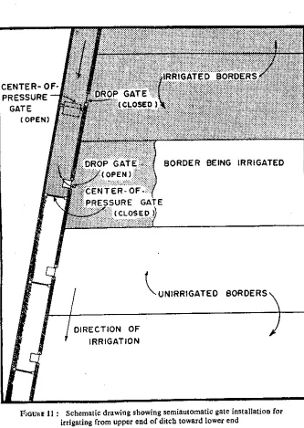
Perhaps the most simple and economical automatic type system is when the center-of-pressure check gate is used as a companion gate to the dorp gate. Since the drop gate must be manually reset, this system is semiautomatic. One use of these two gates in pairs is illustrated in Figure 11. As indicated in this sketch, irrigation proceeds from the up-stream end of the ditch towards the downup-stream end. When irrigating in this manner, the drop gate is placed in the turnout to the field, and the check gate is placed in the head ditch. The outlet into the field may be to a border for that type of irrigation system, or to a spreader ditch or equalizing bay for a furrow irrigation system. The drop gate may be tripped electrically or by a mechanical timer, and when released, the flow of water into the field is stopped. This causes the water in the ditch to rise to the .level required to trip the check gate. The water then proceeds down the ditch to the next pair of gates where the operation is repeated. Thus, irrigation proceeds down the ditch, irrigating each border or field segment in sequence. The gates may also be operated in the manner described above to form a flow diversion structure to automatically divert water from one supply ditch
to another,
DROP GAT OPEN2
ENTER0 -ESSURE GATE
(CLOSED ))
BORDER BEING IRRIGATED
UNIRRIGATED
DIRECTION OF IRRIGATION
FIGURE 11 : Schematic drawing showing semiautomatic gate installation for
IJNIRRIGATED BORDERS
DROP GATE ( OPEN )
CENTERj-PRESSURE GA
DROP GA
(CLOSED)
DIRECTION OF IRRIGATION
24.260
24.261
iopens. Irrigation proceeds in this manner toward the upper end of the head ditch. This system may not be practical where long irrigation time periods are involved unless a special timer is used which does not operate until irrigation begins in the next border downstream('). For long irri-gation periods, conventional timers are usually not available on which a total length of time exceeding 12 hours can be set. In some cases, such as when the supply ditch has a relatively steep slope, the pressure gate in this system may be replaced by a sill or stationary crest at the field 11 turnout.
1 The advantage of the second system is that a pressure gate may be
4 used to automatically divert water to another field or into a ditch leading to another portion of the farm when the last drop gate closes. For this to be accomplished with the system shown in Figure 11, an electrical or hydraulic signal must be sent from the lower end of the ditch to the upper end to operate gates which would divert water from one head ditch into another. Besides the mechanical timer limitation noted above, the head ditch for this system is normally left partially filled with water after each irrigation. Where boding occasionally occurs, and it is desired to keep
irrigation ditches open for passage of the flood waters, it is advantageous to use the first system in which irrigation proceeds from the top end of the head ditch toward the lower end. For this system, the pressure gate is installed in the head ditch and, should flooding occur, these gates will open and allow the water to pass through the ditch to the end where it may be conveyed into a wasteway.
Page 24.256:
footnote (2) should be —Calder, G. G. and Weston, L. H. Automatic system of farm irrigation, New Zealand Journal of Agriculture, Vol. 112, No. 2, February 1966.
Page 24.258:
Third line under subheadingSemia utomatic Irrigation Systems: the word