RESEARCH NOTE
STUDIES WITH A GENERALIZED NEURON BASED
PSS ON A MULTI-MACHINE POWER SYSTEM
D. K. Chaturvedi
Faculty of Engineering, Dayalbagh Educational Institute Dayalbagh, Agra, 282005, India, [email protected]
O. P. Malik
Department of Electrical and Computer Engineering, University of Calgary 2500, University Drive, N.W., Calgary, AB, T2N 1N4, Canada, [email protected]
P. K. Kalra
Department of Electrical Engineering, Indian Institute of Technology Kanpur, U.P, 208016, India, [email protected]
(Received: November 10, 2003 – Accepted in Revised Form: May 10, 2004)
Abstract
An artificial neural network can be used as an intelligent controller to control non-linear, dynamic system through learning. It can easily accommodate non-linearities and time dependencies. Most common multi-layer feed-forward neural networks have the drawbacks of large number of neurons and hidden layers required to deal with complex problems and require large training time. To overcome these drawbacks, a generalized neuron based non-linear controller has been developed and illustrated as a power system stabilizer. Studies on a five-machine power system show that the proposed controller can significantly improve the dynamic performance and provide good damping of the power system over a wide operating range.
Key Words Power System Stabilizer, Neural Network, Low Frequency Oscillation, Neuro-PSS, Generalized Neuron, Multi-Machine Power System
ﻩﺪﻴﻜﭼ
ﻩﺪﻴﻜﭼ
ﻩﺪﻴﻜﭼ
ﻩﺪﻴﻜﭼ
ﯽﻣ ﯽﻋﻮﻨﺼﻣ ﯽﺒﺼﻋ ﻪﮑﺒﺷ
ﻝﺮﺘﻨﮐ ﯼﺍﺮﺑ،ﺪﻨﻤﺷﻮﻫ ﻩﺪﻨﻨﮐﻝﺮﺘﻨﮐ ﮏﻳ ﺕﺭﻮﺼﺑ ﺵﺯﻮﻣﺁ ﻖﻳﺮﻃ ﺯﺍ ﺪﻧﺍﻮﺗ
ﺩﻭﺭﺭﺎﮑﺑﯽﻄﺧﺮﻴﻏﯼﺎﻳﻮﭘﯼﺎﻫﻢﺘﺴﻴﺳ
.
ﯽﻣﻪﮑﺒﺷ
ﻝﺎﻤﻋﺍﺍﺭﻥﺎﻣﺯﻪﺑﯽﮕﺘﺴﺑﺍﻭﻭﻥﺩﻮﺑﯽﻄﺧﺮﻴﻏﯽﮔﺩﺎﺳﻪﺑﺪﻧﺍﻮﺗ
ﺪﻳﺎﻤﻧ
.
ﻭﺮﺸﻴﭘﻪﻳﻻﺪﻨﭼﯽﺒﺼﻋﯼﺎﻫﻪﮑﺒﺷﺐﻠﻏﺍ ،
ﺐﺒﺳ ﻪﺑ
ﯽﻔﺨﻣﯼﺎﻫﻪﻳﻻﻭﻥﻭﺭﻮﻧﺩﺎﻳﺯ ﺭﺎﻴﺴﺑﺩﺍﺪﻌﺗ
ﻡﺯﻻ ﯼﺍﺮﺑ
ﻭﻩﺪﻴﭽﻴﭘﻞﺋﺎﺴﻣﻞﺣ
ﻥﺩﻮﺑﻲﻧﻻﻮﻃ
ﺵﺯﻮﻣﺁﻥﺎﻣﺯ
ﻱﺍﺭﺍﺩ
ﻒﻌﺿ ﻨﺘﺴﻫ ﺪ
. ﻦﻳﺍﺎﺑﻪﻠﺑﺎﻘﻣﯼﺍﺮﺑ ﻒﻌﺿ
ﺎﻫ ،
ﻝﺮﺘﻨﮐﮏﻳ
ﮏﻳﺕﺭﻮﺻﻪﺑﻭﻩﺪﺷﻩﺩﺍﺩﻪﻌﺳﻮﺗﻥﻭﺭﻮﻧﯼﺎﻨﺒﻣﺮﺑﻩﺪﺷﻩﺩﺍﺩﻢﻴﻤﻌﺗﯽﻄﺧﺮﻴﻏﻩﺪﻨﻨﮐ
ﺕﺭﺪﻗﻢﺘﺴﻴﺳﻩﺪﻨﻨﮐﺖﻴﺒﺜﺗ
ﺖﺳﺍ ﻪﺘﻓﺭﺭﺎﮑﺑ
. ﺎﺑﺕﺭﺪﻗﻢﺘﺴﻴﺳﮏﻳﯼﻭﺭﺕﺎﻌﻟﺎﻄﻣ ۵
ﺭﺎﺘﻓﺭﻩﺪﺷﻪﺋﺍﺭﺍﻩﺪﻨﻨﮐﻝﺮﺘﻨﮐﻪﮐﺖﺳﺍﻩﺩﺍﺩﻥﺎﺸﻧﻦﻴﺷﺎﻣ
ﻬﺟﻮﺗ ﻞﺑﺎﻗ ﺭﻮﻄﺑ ﺍﺭ ﯽﮑﻴﻣﺎﻨﻳﺩ ﻲ
ﻩﺩﻭﺪﺤﻣ ﺭﺩ ﻭ ﻩﺩﺍﺩ ﺩﻮﺒﻬﺑ
ﻱﺍ
ﺑﻮﺧ ﯽﻳﺍﺮﻴﻣ ﻊﻴﺳﻭ ﻲ
ﺭﺩ
ﻢﻫﺍﺮﻓ ﺕﺭﺪﻗ ﻢﺘﺴﻴﺳ
ﯽﻣ ﺩﺯﺎﺳ
.
1. INTRODUCTION
Use of a supplementary control signal in the excitation system and/or the governor system of a generating unit can provide extra damping for the system and thus improve its dynamic performance [1]. Power System Stabilizers (PSSs) aid in maintaining power system stability and improve dynamic performance by providing a supplementary signal to the excitation system. This is an easy,
economical and flexible way to improve power system stability. Over the past few decades, PSSs have been extensively studied and successfully used in the industry.
field experiments, this type of PSS has made a great contribution in enhancing the operating quality of the power system [2,3].
With the development of increasingly complex power systems and increasing demand for quality electricity, it is worthwhile looking into the possibility of using modern control techniques. The linear optimal control strategy is one possibility that has been proposed for supplementary excitation controllers [4]. Preciseness of the linear model to represent the system and the difficulty of measurement of some states are major obstacles to the application of the optimal controller in practice. A more reasonable design of the PSS is based on the adaptive control theory as it takes into consideration the non-linear and stochastic characteristics of the power systems [5]. This type of stabilizer can adjust its parameters on-line according to the operating condition. Intensive studies have shown that the adaptive stabilizer can not only provide good damping over a wide operating range but more importantly, there is no coordination problem with the existing CPSSs. Response time of the controller is the key to a good closed loop performance of the power system. Many adaptive control algorithms have been proposed in the recent years; generally speaking, the better the closed loop system performance is desired, the more complicated the control algorithm becomes, thus needing more on-line computation time to calculate the control signal.
More recently, multi-layer artificial neural networks (ANNs) [6-10] and fuzzy set theoretic approach [11-13] have been proposed for power system stabilization problems. Both techniques have their own advantages and disadvantages.
Integration of these approaches can give improved results.
The common neuron model has been modified to obtain a generalized neuron (GN) model using fuzzy compensatory operators as aggregation operators to overcome the problems such as large number of neurons and layers required for complex function approximation, which not only affect the training time but also the fault tolerance capabilities of the ANN [14].
A preliminary study with GN based PSS (GNPSS) on a single machine infinite bus system was described in [15]. Interconnected power systems, however, have multi-modal oscillations and it is necessary to investigate the response of the PSS to the local mode and inter-area mode oscillations. Performance of the GNPSS in a multi-mode oscillation environment is illustrated in this paper.
2. DEVELOPMENT OF A GENERALIZED NEURON MODEL
The general structure of the common neuron is an aggregation function and its transformation through a filter. It is shown in the literature [16-18] that the ANNs can be universal function approximators for given input - output data. The common neuron structure, Figure 1, has summation as the aggregation function with sigmoidal, radial basis, tangent hyperbolic or linear limiters as the threshold function.
The aggregation operators used in the neurons are Generally crisp. However, they overlook the
Σ
∫
OutputInput
Aggregation Thresholding Function Function Bias
Figure 1. Simple neuron model.
ΣΣΣΣ
1f1
ΣΣΣΣ
2ππππ
f2
Outputs_bias
pi_bias
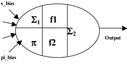
fact that most of the processing in the neural networks is done with incomplete information at hand. Thus, a generalized neuron model approach using the fuzzy compensatory operators [19], that are partly sum and partly product to take into account the vagueness involved, has been adopted.
A. Generalized Neuron Model
Use of the sigmoidal threshold function and ordinary summation or product as aggregation function in the common neuron model (Figure 1) fails to cope with the non-linearities involved in real life problems. To deal with these, the proposed model has both sigmoidal and Gaussian functions with weight sharing. The generalized neuron model has flexibility at both the aggregation and threshold function level to cope with the non-linearity involved in the type of applications dealt with. The neuron has both Σ and π aggregation functions. The Σ aggregation function has been used with the sigmoidal characteristic function (f1) while the π aggregation function has been used with the Gaussian function (f2) as a characteristic function. The final output of the neuron is a function of the two outputs OΣ and Oπ with the weights, W and (1-W), respectively, as shown in Figure 2.The neuron model described above is known as the summation type compensatory neuron model, since the outputs of the sigmoidal and Gaussian functions are summed up. Although a product type compensatory neuron model may also be developed, it is found that in most applications summation type compensatory neuron model works well [19] and is the one used for the development of the GNPSS.
B. Advantages of GN
The number of weights in the case of a GN is equal to twice the number of inputs plus one, which is very low in comparison to a multi-layer feed-forward ANN. The weights are determined through training. Hence, by reducing the number of unknown weights, training time as well as the minimum number of patterns required for training can be reduced. In the proposed GN the training time is reduced by optimally selecting the number of aggregation functions and threshold functions. A comparison of the training and performance of the GN and ANN models is given in [14, 20, 21]. As example, the training time for GN versus ANN was found to bein the ratio of 760: 850 in [20] for a short-term load-forecasting problem.
In this paper, summation and product are used at the aggregation level for simplification, although it is also possible to take other fuzzy aggregation operators such as max, min or compensatory operators. Similarly, only the sigmoidal and Gaussian threshold functions are used for the proposed GN, though other functions like straight line, sine, cosine, etc. can also be used. The weighting factor may be associated with each aggregation function and threshold function. During training, these weights change and decide the best functions for the GN.
C. Learning Algorithm of a Generalized
Neuron
The following steps are involved in the training of a generalized neuron:Step 1. The output of
the
Σ
1 part of the generalized neuron ise
s s netO
_ * 1
1
λ − + =
Σ
where
s
_
net
=
∑
W
ΣiX
i+
X
oΣStep 2. The output of
the
π
part
of the generalized neuron is:e
p pi netO * _
2
λ
− =
Π
where
pi
_
net
=
∏
W
ΠiX
i*
X
oΠStep 3. The output of the generalized neuron can be written as:
W
O
W
O
O
pk=
Π*
(
1
−
)
+
Σ*
inputs:
Error
Ei
=
(
Yi
−
Oi
)
Then, the sum-squared error for convergence of all the patterns is:
∑
=
0
.
5
Ei
2Ep
A multiplication factor of 0.5 has been taken to simplify the calculations.
Step 5. Reverse pass for modifying the connection strength.
(a) Weight associated with the Σ1 and Σ2 parts of the GN is:
W
k
W
k
W
(
)
=
(
−
1
)
+
∆
(6)where:
)
1
(
)
(
−
+
−
=
∆
W
ηδ
kO
ΣO
ΠXi
α
W
k
and:
∑
−
=
(
Yi
Oi
)
k
δ
(b) Weights associated with the inputs of the Σ1 and Σ2 part of the GN are:
i i
i
k
W
k
W
W
Σ(
)
=
Σ(
−
1
)
+
∆
Σ (7)where:
)
1
(
−
+
=
∆
W
Σiηδ
ΣjXi
α
W
Σik
and:
Σ Σ Σj
=
∑
δ
kW
(
1
−
O
)
*
O
δ
(c) Weights associated with the inputs of the π part of the GN are
i i
i
k
W
k
W
W
Π(
)
=
Π(
−
1
)
+
∆
Π (8)where:
)
1
(
−
+
=
∆
W
Πiηδ
ΠjXi
α
W
Πik
and:
Π
Πj =
∑
δk(1−W)*(−2*pi_net)*Oδ
α is Momentum factor for better convergence and η is Learning rate. Range of these factors is from 0 to 1 and is determined by experience.
4. CONVENTIONAL PSS
The CPSS is a fixed parameter device. The input of the CPSS, usually obtained from speed or a related signal such as the frequency, is processed through a suitable network to obtain the desired phase relationship [22,23]. Configuration of a practical CPSS is discussed thoroughly in [3].
5. GNPSS AND ITS TRAINING
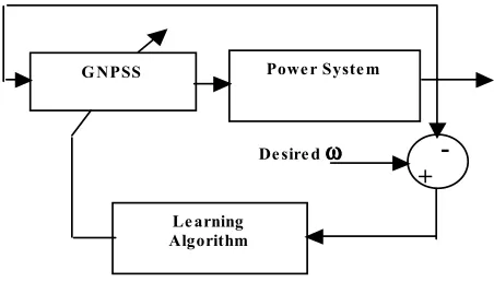
A block diagram of the GN controller as a PSS on a generator is shown in Figure 3. The power system consists of a single machine connected to a constant voltage bus through a double circuit transmission line. The angular speed of the synchronous machine, sensed at fixed time intervals, is used as input to the GNPSS. The GNPSS calculates the output or control action. Parameters of the dynamic model of the synchronous machine constant voltage bus system are given in the Appendix.
Training of an ANN is a major exercise, because it depends on various factors such as the availability of sufficient and accurate training data, suitable training algorithm, number of neurons in the ANN, number of ANN layers and so on. The
Powe r Syste m G NPSS
Le arning Algorithm
De sire d ωωωω -
+
GNPSS with only one neuron is able to cope with the problem complexity, as the selection of the number of neurons and layers is not required. Performance depends upon the training of the GN. Data used for training must cover most of the working range and working conditions in order to get good performance. Of course it is impossible to train any ANN under all working conditions that the controller is likely to meet. Still most of the
working conditions must be included in the training. The current and past three generator speed signals (i.e. ω (t), ω (t-T), ω (t-2*T), and ω (t-3*T), where T is the sampling period), and past three values of the PSS output are used as inputs to the GN. Hence, the input vector for the GN can be written as:
Xi=[ω (t), ω (t-T), ω (t-2*T), ω (t-3*T),
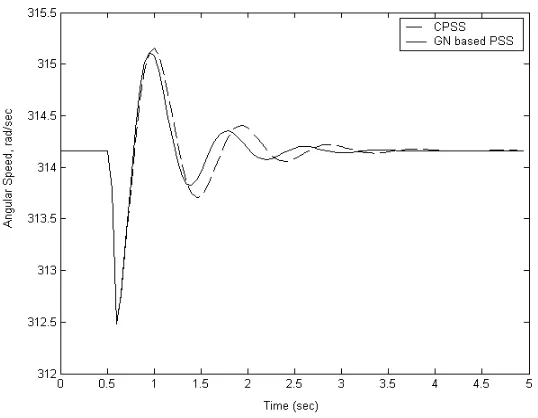
Figure 4. Performance of GN-PSS and CPSS for a 3-phase ground fault.
u(t-T), u(t-2*T), u(t-3*T)] (9)
The output of the GN is the control signal u, which is a function of the deviation in angular speed and past control signals.
Training data for the GN is acquired from the system controlled by the CPSS. For this, the CPSS is tuned for each operating condition. The GN is trained over a wide working range of the generator, i.e. output ranging from 0.1pu to 1.0 pu and the power factor ranging from 0.7 lag to 0.8 lead. Similarly, a variety of disturbances, like change in reference voltage, governor input torque variation, one transmission line outage and three phase fault on one circuit of the double circuit transmission line are also included in the training data.
6. RESULTS
A number of simulation studies were initially performed to study the performance of the GNPSS on a single machine. In this environment there are no multi-mode oscillations. To verify the damping ability of the GNPSS, the performance of the GNPSS was then investigated in a multi-machine power system environment.
6-1. Single Machine Constant Voltage
Bus
System
A. CPSS Parameter Tuning With the generator operating at P = 0.9 pu and Q = 0.4 pu lag, a 100 ms three phase to ground fault is applied at 0.5s at the generator bus. The CPSS is carefully tuned under the above conditions to yield the best performance and its parameters are kept fixed for all studies.
B. Three-Phase to Ground Fault A number of studies were performed for a 100 ms three-phase to ground transient fault at generator bus under different operating conditions. Results for the initial operating condition of P = 0.9 pu and Q = 0.4 pu lag are shown in Figure 4. Because the CPSS has been tuned for P = 0.9 pu, Q = 0.4 pu lag, performance at this operating condition as shown in Figure 4 is practically the same for both the GNPSS and the CPSS. In all figures, performance with GNPSS is shown by solid lines and with CPSS by dashed lines.
C. Operating Point Change The GNPSS performance is studied for a sudden change in the power input reference by 20% of its initial value. Results given in Figure 5 show that the angular
Bus
G #3
G #2
G #5
G #1
G #4
Bus
Load
Load
Load
Bus
Bus
Bus
Bus
speed deviations are damped quickly with the GNPSS.
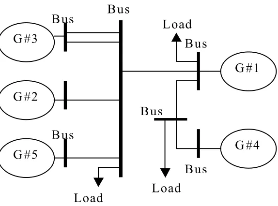
6.2 Multi-Machine System
A five-machine power system without infinite bus, shown in Figure 6, is used to study the performance of the previously trained GNPSS in the presence of multi-mode oscillations. In this system, generators # 1, # 2 and # 4 have much larger generatingcapacity than generators #3 and #5. All five generators are quipped with governors, AVRs and exciters. Parameters of all generators, transmission lines, loads and operating conditions are given in the Appendix.
The whole system can be viewed as a combination of two areas connected through a tie line between buses # 6 and bus # 7. Generators # 1 and #4 form one area and generators #2, #3 and#5
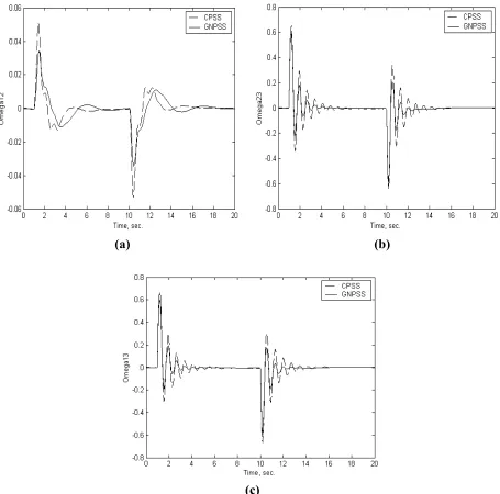
(a) (b)
(c)
Figure 7. System Response with only GNPSSs and only CPSSs installed on G1, G2, and G3 for 30% step
form another area. Under normal operating condition, each area serves its local load and is almost fully loaded with a small load flow over the tie line. When a disturbance happens in the system, multi-mode oscillations arise because of the different inertias of the generators and the topology of the system.
A. Torque Reference Change
A 30% stepdecrease in torque reference of generator #3 is applied at 1s and returns to its original level at 10s. Results with only GNPSS and only CPSS applied at generators #1, #2, and #3 are shown in Figure 7. The following parameters are set for the CPSS:
For small capacity generator #3:
Ka=0.2, T1=T3=0.07, T2=T4=0.03, T5=0.3
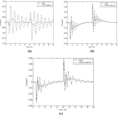
(a) (b)
(c)
Figure 8. System response with GNPSSs on G1, G3 and CPSSs on G2, G4, G5 for one line removed at 1s
For large capacity generators # 1 and # 2:
Ka = 0.5, T1 = T3 = 0.3, T2 = T4 = 0.1, T5 = 0.4
Oscillations between large generators # 1 and # 2 (Figure 7a) in different areas exhibit the low frequency inter-area mode and oscillations between generators # 2 and # 3 in the same area exhibit the higher frequency local mode. It can be seen that both modes are damped very effectively.
B. Coordination between GNPSS and
CPSS
The advanced PSSs will not replace all CPSSs operating in a system at the same time. Therefore, operation of the GNPSSs and CPSSs working together needs to be investigated. In this test, the proposed GNPSS is installed on generators # 1 and # 3; CPSSs with the above mentioned parameters are installed on generators # 2, # 4 and # 5. The operating conditions are the same as given in the Appendix. System response for sudden removal of one transmission line between bus # 3 and bus # 6 at 1s and reconnected at 10s is shown in Figure 8. The results demonstrate that two types of PSSs can work cooperatively to damp oscillations in the system.7. CONCLUSIONS
A generalized neuron, that can incorporate the non-linearities involved in the system, is described in this paper. It uses only one neuron and is trained using back-propagation learning algorithm. Because it has a much smaller number of weights than the common multi-layer feed-forward ANN, the training data required is drastically reduced. Training time is also reduced considerably, because the number of weights to be determined is much less than an ANN.
GN has been employed to perform the function of a PSS to improve the stability and dynamic performance of a multi-machine power system. Simulation studies described in the paper show that the performance of the GNPSS provides good performance over a range of operating conditions. The effectiveness of the GNPSS to damp multi-mode oscillations in a five-machine power system provides satisfactory results and it can cooperate with other CPSSs.
8. APPENDIX
A.
Single Machine Infinite Bus System
The generating unit is modeled by seven first order non-linear differential equations [6]. Parameters used in the simulation studies of single machine constant voltage bus system are given below:ra = 0.00528, rf = 0.00116, rkd = 0.0179, rkq = 0.0179, xmd= 1.74, xmq = 1.65, xf = 0.16, xkd = 0.09, xkq = 0.146,
H = 5.83, kd = 0.027
Tg = 0.1, Ts = 0.3, kg = 0.0796
ka = 0.001; Ta = 0.01; ke = 5.56; TTe = 0.01 Rt = 0.06, Xt = 0.25
Rtr = 0.008, Xtr = 0.10
All resistances and reactances are in per unit and time-constants in seconds.
B. Multi-Machine Power System
1. Generator Parameters For small generators # 3 and # 5:
xd = 1.026, xq = 0.6580, xd’= 0.3390: xd’’= 0.2690, xq’’= 0.3350, H = 20:
For large generators # 1, # 2 and # 4:
xd = 0.1026, xq = 0.0658, xd’= 0.0339: xd’’= 0.0269, xq’’= 0.0335, H = 100: Time constant for all generators:
Tdo’=0.3670, Tdo’’=0.0314, Tqo’’= 0.0623.
2. Simplified IEEE Standard Type ST1A AVR and Exciter Model Tr = 0.04, Ka = 190.0, Kc = 0.08, Ta = 10.0, Tc = 1.0.
3. Governor Model
δ
dt
d
sTg
b
a
g
]
1
[
+
+
=
where:
Tg = 0.25, a = -0.00133, b = -0.0150.
Transfer Function
)
(
)
1
(
)
1
(
)
1
(
2 1s
sT
sT
sT
sT
k
u
w w gpss
∆
ω
+
+
+
−
=
6. Loads Admittance (pu)
L1 = 7.5 – j 5.0, L2 = 8.5 – j 5.0, L3 = 7.0 – 4.5.
9. REFERENCES
1. DeMello, F. P. and Laskowski, T. F., “Concepts of Power System Dynamic Stability”, IEEE Trans. on Power Apparatus and Systems, Vol. PAS-94, (1979), 827-833.
2. DeMello, F. P., Hannett, L. N. and Undrill, J. M., “Practical Approaches to Supplementary Stabilizing from Accelerating Power”, IEEE Trans. on Power Apparatus and Systems, Vol. PAS-97, (1978), 1515-1522.
3. Larsen, E. V and Swann, D. A., “Applying Power System Stabilizer”, IEEE Trans. on Power Apparatus and Systems, Vol. PAS-100, 1981, 3017-3046.
4. Ohtsuka, K. S., Yokokama, Tanaka, H. and Doi, H., “A multivariable optimal control system for a generator”, IEEE Trans. on Energy Conversion, Vol. EC-1, (1986), 88-98.
5. DA, Pierre, “A Perspective on Adaptive Control of Power Systems”, IEEE Trans. on Power Systems, Vol. PWRS-2, No. 2, (1987), 387-396.
6. Zhang, Y., Chen, G. P., Malik, O. P. and Hope, G. S., “An Artificial Neural Network Based Adaptive Power System Stabilizer”, IEEE Trans. on Energy Conversion, Vol. EC-8, No. 1, (1993), 71-77.
7. Swidenbank, E., McLoone, S., Flym, D., Irwin, G. W., Brown, M. D. and Hogg, B. W., “Neural Network Based Control for Synchronous Generators”, IEEE Trans. on EnergyConversion, Vol. 14, No.4, Dec. (1999), 1673-1679.
8. Changaroon, B., Srivastava, S. C. and Thukaram, D., “A Neural Network Based Power System Stabilizer Suitable for On-Line Training - A Practical Case Study for EGAT System”, IEEE Trans. on Energy Conversion, Vol. 15(1), (2000), 103-109.
9. Segal, R., Kothari, M. L. and Madnani, S., “Radial Basis Function (RBF) Network Adaptive Power System Stabilizer”, IEEE Trans. on Power Systems, Vol. 15, (2000), 722-727.
10. Hsu, Yuan-Tih. and Chao-Rong, Chen., “Tuning of Power System Stabilizer using an Artificial Neural Network”, The Proceedings of the IEEE/PES Winter Meeting, New York, (Feb. 3-7, 1991).
11. Abido, M. A., and Abdel-Majid, Y. L., “Tuning of Power System Stabilizers using Fuzzy Basis Function Networks”, ElectricMachines and Power Systems, Vol. 27, (1999), 865-877.
12. Hiyama, T. and Sameshima, T., “Fuzzy Logic Control Scheme for On-line Stabilization of Multi-machine Power System”, Fuzzy Sets and Systems, Vol. 39, (1991), 181-194.
13. Hosseinzadeh, N. and Kalam, A., “A Direct Adaptive Fuzzy Power System Stabilizer”, IEEE Trans. on Energy Conversion, Vol. 14(4), (Dec. 1999), 1564–1571. 14. Chaturvedi, D. K. Satsangi, P. S. and Kalra, P. K., “Load Frequency Control: A Generalized Neural Network Approach", Int. J. of Electric Power and Energy Systems, Vol. 21, (1999), 405-415.
15. Chaturvedi, D. K., Malik, O. P. and Kalra, P. K., “Power System Stabilizer using a Generalized Neural Network”, 34th North American Power Symposium, Arizona State
University, Arizona, USA, (Oct. 14-15, 2002).
16. Hornik, K. Stinchombe, M. and White, H., “Multi-layer Feed Forward Networks are Universal Approximators”, Neural Networks, Vol. 2, (1989), 359-366.
17. Laurence Fausett, "Fundamentals of Neural Networks, Architecture, Algorithms, and Applications", Prentice Hall, Englewood Cliff, NJ, (1994).
18. Widrow, B. and Lehr M. A., "30 Years of Adaptive Neural Networks: Perceptrons, Madaline, and Back Propagation", Proc. IEEE, Vol. 78(9), (1990), 1415-1442.
19. Mizumoto, M, “Pictorial Representations of Fuzzy Connectives, Part II: Cases of Compensatory Operators and Self - Dual Operators”, Fuzzy Sets and Systems, Vol. 32, North-Holland, (1989), 45-79.
20. Chaturvedi, D. K., Satsangi, P. S. and Kalra, P. K., “Fuzzified Neural Network Approach for Load Forecasting”, Engineering Intelligent Systems, Vol. 9(1), (2001), 3-9.
21. Chaturvedi, D. K., Satsangi, P. S. and Kalra, P. K., “New Neuron Models for Simulating Rotating Electrical Machines and Load Forecasting Problems”, Electric Power SystemsResearch, Vol. 52, (1999), 123-131. 22. Rogers, G. J., “The Application of Power System
Stabilizers to a Multi-Generator Plant”, IEEE Transactions on PowerSystems, Vol. 15 Issue: 1, (Feb. 2000), 350-355.