Published online January 17, 2015 (http://www.sciencepublishinggroup.com/j/jeee) doi: 10.11648/j.jeee.s.2015030201.16
ISSN: 2329-1613 (Print); ISSN: 2329-1605 (Online)
Evaluation of uncertainties on the performance of distance
relay
Seyyd Mahmood Mosavi
1, 21
Khorasan Regional Electric Company, Mashhad, Iran 2
Department of Electrical Engineering, College of Ebne Yamin, Sabzevar, Iran
Email address:
To cite this article:
Seyyd Mahmood Mosavi. Evaluation of Uncertainties on the Performance of Distance Relay. Journal of Electrical and Electronic Engineering.
Special Issue: Research and Practices in Electrical and Electronic Engineering in Developing Countries. Vol. 3, No. 2-1, 2015, pp. 25-29. doi: 10.11648/j.jeee.s.2015030201.16
Abstract:
Global demand growth for electric energy has speed up development in designing power systems in order to meet users' needs for providing reliable, cheap and high quality electric energy. In power networks the first zone of distance relay is considered as main protection for transmission lines. Zones 2 and 3 of this relay are considered as supporting protection for next lines. Distance relay can be affected by many factors which are not clear and definite. These factors which are considered as uncertainties are fault resistance, fault in measurement transformers, ground resistance, and change in structure and exploitation conditions. In this article we prove their considering uncertainties approaches zone 1 distance relay extent to 100 percent of protected line provides more reliable protection for transmission lines.Keywords:
Distance Relay, Uncertainty, Zone, Protection1. Introduction
Global demand growth for electric energy has speed up development in designing power systems in order to meet users' needs for providing reliable, cheap and high quality electric energy. From the beginning of this industry the problem of electric energy production, transmission and distribution was always accompanied with likely faults and reliability problem [3]. Task of protection system is fast and timely detection of unusual conditions in power system and running revisions in order to restore power system to usual conditions [4]. One of the important elements of power system is transmission line which transfers energy from producer to consumer. Protection of transmission line is done by distance relay and high current [3]. These relays not only act as main protection but also they are used as supporting protection [1]. Distance relay detects fault location through measuring path impedance between relay location and short circuit. However there are factors which have undesirable effect on distance relay and disrupt their performance; Therefore, investigating them and presenting suitable solution has special importance in preventing these factors [3].
2. Effective Uncertainties on Distance
Relay Performance
2.1. Fault Resistance
Fault resistance has undesirable effect on distance relay performance as an unknown phenomenon and usually is considered as an important uncertainty. If fault resistance was zero, measured impedance in relay point is only dependent on the part of tool which is located between relay and line but if resistance was non-zero, measured impedance is not equal with part of line which is located between relay and fault point. Therefore, fault tolerance results in uncertainty in distance relay [2].
2.2. Fault in Measurement Transformers (PT, CT)
voltage transformer) and it will influence distance relay performance.
2.3. Ground Resistance
Ground resistance is another uncertainty which is considered for single phase to ground faults. In this case, measured impedance by relay will be equal with sum, line impedance between relay and fault location and fault resistance and ground resistance. As ground resistance in each zone is different from other zones because of ground especial resistance, soil type and humidity, it will influence correct relay performance [3].
2.4. Change in Structure and Exploitation Conditions
Since distance relay settings are those settings which are stable and impose offline for worst case fault in system and relay, therefore, by changing structure and exploitation of network distance relay performance will suffer. In fact when network structure changes, network impedance and short circuit in network will change as well. Change in exploitation condition creates this problem. By increasing or decreasing load or production of plants network voltage will change [3].
3. Related Works
In a research study, Sidha al,[9] presented a new approach for calculating zone 2 distance relay settings and its application in comparative protection. They presented two comparative and non-comparative algorithms for calculating zone 2 settings in response to change in exploitation condition. In non-comparative algorithm, impedance is calculated for maximum and minimum and production and zone 2 as worst case but in comparative method online awareness from exploitation is presented and new settings impose in relay per each change. This method provides better support and coverage for zone 2 [9].
In another study, Jamali and Shateri [4] calculated the maximum fault resistance regarding measured impedance in relay point for which distance relay with tetrahedron characteristics has desired performance.
Furthermore Benteghi et. al, [11] presented comparative distance relay based on cvt transient fault estimation. They presented the following issues:
Measurement impedance is obtained by dividing ct and cvt voltage and current. Therefore, it influences cvt transient voltage fault influences this impedance and leads it to saturation point. Measured impedance includes ohm and self-parts. Based on distance relay parameters, reaching saturation point was caused by reactance fault. Therefore, reactance problem is solved with combining old distance relay with comparative reactance relay [11]. In 2008, Joy Mooni presented an article entitled "distance relay under ct saturation condition". He studied waveform of ct output current in secondary and showed that how saturated ct caused sub-saturation point and up-saturation point and studied effect of ct saturation on zones and direction and distance
relay time [12].
In addition Taqizade et. al, [13], studied the effect of single phase to ground fault with arc-resistance on distance relay performance. They used THD factor (harmonic disturbances) to detect faults along with arc and a comparative distance relay was presented by this factor.
4. Methodology
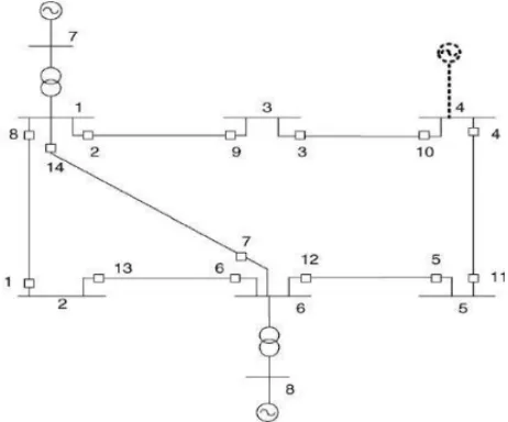
First we are seeking to determine effect of each uncertainty factor on distance relay performance. For this, we design a simple 8 buses network according to IEEE standard as depicted in Figure 1. Then we regulate distance relays of this network based on status quo (without uncertainty), single phase and two phase and three phase faults were simulated in different locations (different zones) and measured impedance by distance relay for each condition was recorded. In the next step, we simulate uncertainties which were used separately for each fault. This time measured impedance by relay was recorded considering uncertainties. It is necessary to mention that some uncertainties are related to each other and influence each other. For example, exploitation conditions influences fault resistance and we should consider it in modeling and model both uncertainties synchronously or some uncertainties have more influence on certain zones. We should consider them to determine their effects. Therefore, effect of each on uncertainties on distance relay performance were determined and prioritized according to importance of these uncertainties.
4.1. Design of a Standard 8-Buses Network
The Mont-Carlo method was used regarding type and nature of problem, purposes and questions. In simulations instead of creating formula for solving problem we try to analyze and test a model for several times in likely conditions and results were recorded each time. Then by analyzing obtained statistics we gain reliable results for real performance of the system.
4.2. Research Methodology
4.2.1. Setting of First Zone
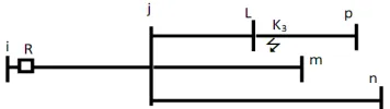
It is expected that relay R in ideal state covers ijth line by its protection i.e. for each fault between buses i and j, relay should be able to detect fault and cut ij circuit. For this purpose, at first glance it seems that if relay R set by ij line impedance this line will be under protection but uncertainties influence measured impedance by relay R and may increase or decrease this impedance.
Assume that there is a fault near bus j (k1). In this case,
current will increase and voltage reduces. If impedance measured by relay increases because of uncertainties, in this case relay R detects this impedance in zone 2 (k2).
Figure 2. Simple three buses network with distance relay for introducing setting zone 1 and 2
However if fault occurs in next line i.e. jL line near bus j and impedance measured by relay decreases because of some uncertainties, relay R detects wrongly fault in zone 2 as zone 1 and cut ij circuit. Therefore, relay R cannot be set by ij line impedance but it is clear that impedance measured by relay R is in following interval because of uncertainties.
Zmin< Zmeas< Zmax (1)
Zmeas€ [Zmin ,Zmax] (2)
In which Zmin is minimum impedance Zmeans is impedance
measured by transformers and Zmax is maximum impedance.
Since zone of one Relay R per faults in next line should not have performance, impedance measured by this relay should be higher than relay set impedance i.e.
Zmin>Z1set [Zmin,Zmax]>Z1set Zmeas>Z1set (3)
In which z1set is set impedance for distance relay.
Therefore, minimum impedance measured by relay R considering uncertainties should be higher than set impedance; Therefore, if three phase fault simulated in end point of line ij and on bus j and repeat it thousand times, minimum impedance measured by relay R in these repetitions can be considered as zone 1 setting in relay R.
Zmin = Z1set (4)
Now we should see that how much percent of line ij is covered by setting relay R without uncertainties i.e. measured impedance by relay in this condition should be lower that set amount to place in relay performance scope. Therefore, we should displace fault on ij line to farthest point for which fault be always Zmeans<Z1set. Therefore, we have:
Zmax<Z1set [Zmin,Zmax]<Z1set Zmeas<Z1set (5)
Therefore, we change fault point on line ij and it is
simulated thousand times in different locations to obtain maximum impedance in each location considering uncertainties. This will be repeated until maximum impedance measured in one place should be equal with zone 1 set by relay which shows that relay covers it as a zone considering uncertainties.
4.2.2. Setting of Zone 2
In order to set zone 2 relay R, we consider following network:
Figure 3. Simple three buses network with distance relay
In ideal condition, relay R should cover all lines connected to bus j as zone 2. Perhaps we consider that of zone 2 was set by jn line impedance we can achieve this but if a short circuit happens on Lp relay wrongly detects it as zone 2 while fault has occurred in zone 3. Therefore, in order to set zone 2 relay R we should consider shortest line connected to bus j and as we discussed about zone 1 relay we should simulate a three phase fault at the end of shortest line with uncertainties. Impedance measured by relay is in
interval. Therefore, the following equation should be hold in order that relay has not performance. Therefore, we have:
Zmin>Z2set [Zmin,Zmax]>Z2set Zmeas>Z2set (6)
We repeat this fault several thousand times. Minimum impedance measured by relay R was considered as zone 2 setting. In following we consider that by setting zone 2 this relay covers some percents of jL line completely considering uncertainties. For this purpose, we should displace fault on line iL to farthest point in which . Therefore, we have:
Zmax<Z2set [Zmin,Zmax]<Z2set Zmeas<Z2set (7)
Therefore, we change fault point on line jL and it is simulated thousand times in several locations to obtain maximum impedance in each location considering uncertainties. His will be repeated until maximum measured impedance become equal with zone 2 setting. In this case, this location shows percent of jL line which relay covers it completely as zone 2 considering uncertainties
4.2.3. Setting of Zone 3
In order to obtain zone 3 relay we consider following network:
At the end of longest line connected to bus j (on bus n) we simulate three phase fault. We assume that in this fault there is uncertainty in measurement device, fault in calculating line impedance and lines' resistance. We repeat this simulation several thousand times. Maximum measured impedance in this repetition is considered as zone 3 setting.
Of course, we should consider that uncertainties mentioned in simulations occur in short circuit or fault not others or it may decrease or increase impedance measured by relay; therefore, in all simulations we consider uncertainties randomly and its value by normal distribution.
In simulations we considered uncertainties of CT and PT faults and faults in calculating line impedance and fault resistance. We considered CT and PT fault as 2% and fault in lines impedance as 1 percent and fault resistance two times of line resistance.
5. Setting Algorithms
Regarding the setting algorithms used for calculating zone setting and obtaining maximum covered area the following details are provided:
5.1. Zone 1 Setting Algorithm
1. Entering network information including introducing buses, line impedance, generators production power, load consumption power.
2. Entering relay number in which zone 1 is placed and line which this relay protects it as zone 1.
3. Imposing one percent fault in lines impedance matrix using normal distribution.
4. Forming network impedance and admittance
5. Raphson-Newton load distribution (for calculating buses voltage before short circuit).
6. Simulation three phase fault on bus j (worst case scenario)
7. Imposing fault resistance randomly in zero to double amount of ij line resistance using normal distribution.
8. Calculating short circuit and obtaining relay voltage and current after short circuit.
9. Imposing 2% fault in relay voltage and current using normal distribution.
10. Calculating seen impedance by relay using following formula and storing in Zsss
For Impedance Relay: ZR=VR/IR and for Admittance Relay:
Zr=(VR/IR)/(cos(φr-φx)
11. Step 9 repeats thousand times.
12. Calculating minimum Zsss and storing in Ztttt
13. Step 7 repeats thousand times. 14. Step 3 repeats thousand times
15. Calculating minimum Ztttt as zone 1 setting
16. end
If R is the impedance relay : ZR=VR/ IR if the relay R is moho:Zr =(VR/ IR)/(COS(φr – φx))
5.2. Zone 2 and Zone 3 Setting Algorithms
Zone 2 and zone 3 setting algorithms is similar to zone 1 setting algorithm with this difference that in step 2 for zone 2 setting enter 2 and line relay is on it (j,i) and shortest next line (L) and zone 3 setting as -2 and longest next line.
5.3. Algorithm for Calculating Maximum Covered Area by Zone 2 Setting
1 Entering network information including buses, lines impedance, power generated by generators, loads consumption power..
2 Entering relay number and line in which relay locates and shortest next line and zone 2 setting.
3 Place a as 1.
4 Change bus 1 location
5 Impose one percent error in impedance matrix using normal distribution.
6 Forming network impedance and admittance
7 Newton load distribution (for calculating buses voltage before short circuit)
8 Simulation three phase fault on bus j (worst case scenario)
9 Imposing fault resistance randomly in zero to double amount of ij line resistance using normal distribution. 10Calculating short circuit and obtaining relay voltage and
current after short circuit.
11Imposing 2% fault in relay voltage and current using normal distribution.
12Step 9 repeats thousand times.
13Calculating maximum Zsss and storing in Ztttt
14Step 7 repeats thousand times. 15Step 3 repeats thousand times
16Calculating maximum Ztttt as zone 1 setting
17If Zmax=Z2SET go to step 20
18Place a=a-(0-01) and go step 4
19a is percent of jl line which relay R covers it/ 20end
6. Discussion & Conclusion
Settings imposeding as distance relay are stable settings which are considered by dominant condition of systems. In these settings effects of factors like fault resistance, measurement devices fault, change in structure and exploitation conditions are not considered which are introduced as uncertainty. In this study we obtained settings for distance relay which cover uncertainties and increase relay accuracy. By considering security marging several setting groups are considered for different conditions of network and by changing condition certain setting groups impose on relay.
References
[1] Shateri, H., & Jamali, S. ideal characteristic for distance relay. International power conference, Tehran, Iran, 1990.
[2] Shateri, H., Jamali, S. fault border resistance for setting distance relay with tetrahedron chaaracteristics. 19th international electricity conference, Tavanir company Tehran. Iran, 2004.
[3] Catalogues, instructions for power networds, Deputy exploit, Khorasan Regional Electricity Company, 2012.
[4] Hashemi, S.M., Tarafdarhaqh, M., & Seyyedi, H. protecting transmission lines equipped with IPFC. Iran. Tabriz University. 6th power systems conference, , 2012.
[5] Tarlochan S.Sidhu , David Sebastian Baltazar , Ricardo Mota Pahomino , and Mohindar S.Sachdev, A New Approach for Calculating Zone-2 Setting of Distance Relays and Its Use in
an Adaptive Protection System , IEEE Transactions on Power Delivery, January ,v01.19 , No.1 , 70, 2004.
[6] H.Shateri , S. Jamali . Measured Impedance by Distance Relay Elements in a Single Phase to Ground Fault , IEEE , 5th International Conference on Electrical and Computer Engineering, 20 _ 22 December , 978_1_4244 , 2008. [7] Benteg He , Yiquan Li , Zhiqian Q.Bo ,An Adaptive Distance
Relay Based on Transient Error Estimation of CVT , IEEE TRRANSACTIONS ON POWER DELIVERY, OCTOBER , VOL.21 , NO.4 , 2006.
[8] Joe Mooney, P.E., Distance Element Performance Underconditions of CT Saturation, IEEE, Schweitzer Engineering Laboratories, Inc., 2008.