Published online March 20, 2014 (http://www.sciencepublishinggroup.com/j/jeee) doi: 10.11648/j.jeee.20140201.13
Application of Rayleigh probability density function in
electromagnetic wave propagation
Mustafa MUTLU
Electronic Communication Department, Technical Sciences MYO, Ordu University, 52200 Ordu, Türkiye
Email address:
To cite this article:
Mustafa MUTLU. Application of Rayleigh Probability Density Function in Electromagnetic Wave Propagation. Journal of Electrical and Electronic Engineering. Vol. 2, No. 1, 2014, pp. 17-21. doi: 10.11648/j.jeee.20140201.13
Abstract:
In this study, signal voltage obtained at the receiver is investigated by taking the Rayleigh Probability Density Function into account. Probability of received signal and occurrence of incoming signal between two levels are also studied. Success percentage, requirement of how much the receiver is to be modified and variation of voltage or power at the output with respect to time are simulated in MATLAB for various physical environments.Keywords: Rayleigh Probability Density Function, Multipath Fading, Fade Depth, Probability of Reception of Signal,
Distribution Function1. Introduction
Rayleigh Probability Density Function (Rayleigh PDF) is used for the cases in which there is non-line of sight (NLOS)[1] between transmitters and receivers for the communication networks and channel modeling. When there occur phase differences between multipath signals arriving the receiver, fading takes place. Rayleigh modeling is used for multipath fading in modeling of change of voltage or power that will be received. In Rayleigh modeling, in contrast to the Ricean, there is no any specified direction, that is, signals coming from any direction are assumed to have equal probability.
Moreover Rayleigh Modeling is used for noise analysis. If a signal coming to a receiver via reflection becomes so greater than the direct signal that it suppresses that, in this case this type of channel modeling is done by means of Rayleigh PDF.
2. Voltage Obtained at the Receiver
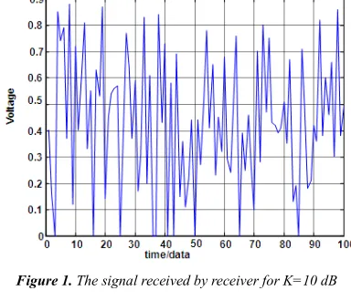
In Figures 1-3 the variation of voltage obtained at the receiver for different K values representing physical environments is shown. Here K is the ratio of the power of the electromagnetic wave received directly; to the electromagnetic wave received by reflection, diffraction and scattering.
Figure 1. The signal received by receiver for K=10 dB
Figure 3. The signal received by receiver for K=20 dB
It can be seen that, as the K value increases the peak value of voltage signal obtained by the receiver decreases. It is also possible to obtain the variation of voltage at the receiver using fz(z). fz(z) is sampled in a particular time
interval and this sampled values are rounded to integer numbers. If we plot these values by using a function that is distributing them randomly, the figures 1-3 are obtained [2].
3. Numerical Plot of Rayleigh
Probability Density Function
It is possible to obtain Rayleigh PDF from the voltage at the receiver. Received signal is sampled in a particular time interval and this sampled values are rounded to integer numbers. when this integer numbers and their number of repetitions, probability of received signal, are plotted and put into an envelope, Rayleigh PDF is obtained. In this plot, vertical axis represents the number of repetition and horizontal axis represents the voltage level. For instance, if 0.21v is repeated 4 times among 100 samples obtained at the receiver, the probability of the occurrence of 0.21 v is 4 percent. An increase in the range of the voltage level at the receiver causes a decrease in the mean of Rayleigh PDF. This leads to a decrease in the probability values around the mean [3].
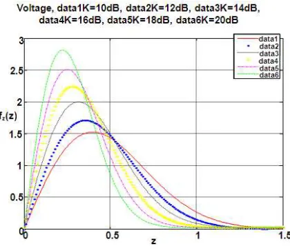
Figure 4. The variation of fz(z) for different K values
4. Transition From fz(z) to Time
Domain
We divide fz(z) with desired steps horizontally, i.e.,
0.01 increments in the example. If we distribute these 100 data values randomly to plot them, we obtain the variation of the signal with respect to time. In this function, the bigger the amplitude K gets, the more the repetition number around the mean occurs. Rayleigh PDF changes with respect to a single parameter, either standard deviation σ or K[4].
⁄ (1)
1 2 ⁄ (2)
0 1 (3) K values are normalized when using in the equation (4). Rayleigh PDF is expressed as,
2 !" # (4) When K represents the power
L K 10⁄ (5) and if it represents the voltage
& ⁄20 (6) is used. For both cases
' 10( (7)
normalized Rayleigh PDF can be written as,
2 ' !" # ' (8) S is obtained through the equations (5), (6), (7) and used in equation (8) to obtain fz(z)[5].
Mean of this function is
) * +, - .0/ , (9)
and the variance is written as,
+, - # + , - 0.2146⁄ (10)
and the standard deviation is
σ 0.4632/√K 11
The probability that a receiver can obtain a voltage level, is found by replacing z by the value of voltage level in fz(z) .
For instance, the probability of 0.15 volt to be obtained is 2.395549 %.
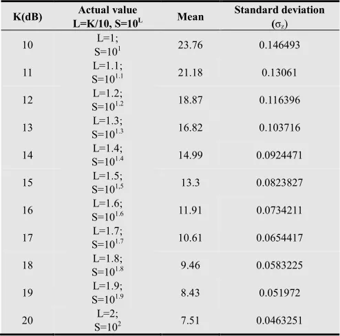
Table 1. K values, Actual K values representing different environments, the mean and the standard deviation for power.
K(dB) Actual value
L=K/10, S=10L Mean
Standard deviation (σz)
10 L=1;
S=101 23.76 0.146493
11 L=1.1;
S=101.1 21.18 0.13061
12 L=1.2;
S=101.2 18.87 0.116396
13 L=1.3;
S=101.3 16.82 0.103716
14 L=1.4;
S=101.4 14.99 0.0924471
15 L=1.5;
S=101,5 13.3 0.0823827
16 L=1.6;
S=101.6 11.91 0.0734211
17 L=1.7;
S=101.7 10.61 0.0654417
18 L=1.8;
S=101.8 9.46 0.0583225
19 L=1.9;
S=101.9 8.43 0.051972
20 L=2;
S=102 7.51 0.0463251
In Table 2, K values, total data number and the number of data having zero probability (Nz) are given. We conclude
from this table that, if K increases Nz and the probability
value increases. Also this shows that low-amplitude voltages can be obtained with a higher probability than high-amplitude voltages. In this table. The data with a probability value smaller than 0.0005 are taken as zero.
Table 2. K values, total data number and Nz are given.
Total data count Nz
K=10 dB (voltage) 10000 2096
K=12 dB (voltage) 10000 2645
K =14 dB (voltage) 10000 3184
K =16 dB (voltage) 10000 3707
K =18 dB (voltage) 10000 4207
K =20 dB (voltage) 10000 4680
Table 3. The relationship between K values, voltage and power means for 100 data.
K(dB) Environment (according to Loo’s
distribution model)
Voltage average
Power average
4 overall 60 47
6.3 İnfrequent light 52 36
10 42 23
11 40 21
12 38 19
13 36 17
14 34 15
15 32 14
16 30 12
17 28 11
18 27 10
18.8 frequent heavy 26 10
19 25 9
20 24 8
For voltage, when the means of the function with respect to K values are taken into consideration, it is seen that they are varying between 0.21 V and 0.6 V. For power, the variations are between 0.08 V-0.48 V. These results show that these levels can be obtained with a high probability in this voltage or power range and the remaining probabilities are close to zero. The lower-voltage levels can be obtained with a higher probability in Rayleigh model. This leads to the extension of the variation range of voltage values by lowering the threshold in the receiver. For instance, for power, the probability of 0.21 volts to be obtained at the receiver for K=10, 12, 14, 16, 18, 20 dB would be 1.11 %; 1.35 %; 1.640 %; 1.960 %; 2.312 %; 2.681 % respectively. Function behaves as a narrow band filter as the K value increases. Bandwidth is inversely proportional with K [6].
5. Obtaining Distribution Function
from fz(z)
Fz(z), the distribution function, is obtained by finding the
area of fz(z).
F9 z . f0/ 9 z dz (12)
Figure 5. The variation of Fz(z) with respect to K
Due to the fact that the total area of fz(z) which is the
sum of probabilities equals to 1. The bigger the peak value of fz(z) gets, the earlier fz(z) goes to zero, and the earlier
Fz(z) goes to 1. Fz(z) is also quite significant as it provides
us with the probability values of any desired voltage level to be less than or equal to a voltage value of z, or the probability of a voltage to occur between two voltages. In addition, this function also supplies us with the probability of the voltage or power to be obtained by the receiver or the occurrence probability of voltage or power. If we are to find the occurrence probability between any two voltages, these two points should be chosen very close, if not it would be possible to observe that the error increases linearly with the distance. In this function, the probability of voltage or power to be occur between any two points can be found with the expression given below[7]
= # = > ? @ ABC (13)
0.23-0.24 V to occur at the receiver is found 2.705570 % by using the equation (13). The sum of the probability values under any value can be found by using Fz(z).
6. Obtaining Gz(z) from Fz(z)
Gz(z) is the failure rate and can be expressed as,
D 1 # = (14)
The earlier Fz(z) function goes to 1, the earlier Gz(z) goes
to zero. This function shows that the value of threshold at the receiver to be decreased in order to get signal at any level. The sum of the probabilities above a value can be found with this function.
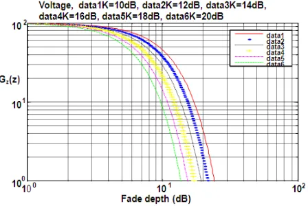
Figure 6. The variation of Gz(z) with respect to K
In Figure 6, Gz(z) is plotted for different K values. In
addition, this figure shows the power to be added to the receiver in order to gain desired success rate. For instance, without any change in the system, the success rate is 0.63 % for K=10 dB. If a power of 10 dB is added to the receiver, the success rate would reach to 64 %, if 20 dB is added, the success rate would reach to 95 % [8].
7. The Variations of fz(z) and Fz(z)
Figure 7. The variation of Fz(z) and fz(z) with respect to voltage level
Figure 7 shows the probability of voltage values obtained
at the receiver and their probability of being below any level.
8. fz(z) and Gz(z) Functions
In Figure 8, the probability of voltage values obtained at the receiver and their probability of being above any level is shown [9].
Figure 8. The variation of fz(z) and Gz(z) with respect to voltage level
9. F
z(z) and G
z(z) Function
In the Figure 9, the success and failure curves of the signal obtained are shown. The curves plotted by the data 1 and data2 values, show the sum of the probabilities of being below and above a value respectively.
Figure 9. The variation of Fz(z) and Gz(z) with respect to voltage level
10. Conclusion
In this study, Rayleigh PDF which is obtained at the receiver according to different K values is used. The mean, and the standard deviation is calculated. Rayleigh PDF, Rayleigh distribution, failure rate and the voltage obtained at the receiver are plotted. We have interpreted the meaning of these concepts at the outdoor NLOS propagation.
References
[1] Mutlu, M. and Çavdar, İ.,Adaptation of COST-231 Walfisch-Ikegami method to Ordu city in GSM 900 frequency band. Electrical, Electronics and Computer Engineering (ELECO), National Conference, pp. 447-453, Bursa,Turkey, 2-5 Dec. 2010.
[2] Papoulis, A. Probability, Random Variables, and Stochastic Processes, McGraw-Hill, New york, 1965.
[3] Goldhirsh J. And Vogel W.J.,Handbook of Propagation Effects for Vehicular and Personal Mobile Satellite Systems, December, 1998.
[4] D. Lu and K. Yao, Improved Importance Sampling Technique for Efficient Simulation of Digital Communication Systems, IEEE Journal on Select. Areas in Commun., vol.SAC-6, no.1, pp.67–75,Jan. 1988.
[5] Mutlu, M. Minimization of the Difference between the Theoretical Mean of the Rayleigh Probability Density Function and the Mean Obtained from its Plot. Universal Journal of Electrical and Electronic Engineering pp. 23 - 29 DOI: 10.13189/ujeee.2014.020104 Vol 2 No 1, New york, Jan 2014
[6] Lee, W. C. Y. Mobile Communications Design Fundamentals, H. W. Sams and Co.,Indianapolis, Indiana, 1986.
[7] Abramowitz, M and I. Stegun,Handbook of Mathematical Functions,NBS AppliesMathematics Series, Vol. 55, U.S. Govt. Printing Office, Washington, DC.,20402.1964. [8] Clarke, R. H, A Statistical Theory of
Mobile-RadioReception, Bell System Technical Journal, Vol. 47, No. 6, July-August, pp. 329-339 .1968.