Magnetic Gearing System
Yadhu Raj Vishnu M Nair
UG Student UG Student
Department of Mechanical Engineering Department of Mechanical Engineering Saintgits College of Engineering, Kottayam, Kerala Saintgits College of Engineering, Kottayam, Kerala
Libin K Varghese Martin Vincent
UG Student UG Student
Department of Mechanical Engineering Department of Mechanical Engineering Saintgits College of Engineering, Kottayam, Kerala Saintgits College of Engineering, Kottayam, Kerala
Davis Wilson
Assistant Professor
Department of Mechanical Engineering Saintgits College of Engineering, Kottayam, Kerala
Abstract
With the advent of magnetic gears, researchers have developed a new breed of permanent-magnet machines. These magnetic-geared permanent-magnet machines artfully incorporate the concept of magnetic gearing into the permanent-magnet machines, leading to achieve low-speed high-torque direct-drive operation.Gears and gearboxes are extensively used for speed change and torque transmission in various industrial applications. It is well known that the mechanical gear has a high torque density, but suffers from some inherent problems such as contact friction, noise, heat, vibration and reliability are of great concern. In order to avoid these types of problems we are using magnetic meshing gears. That is the gears are meshed together with the help of magnetic force of attraction without making into contact. By using such kind of gearing systems we can reduce the wear and tear that are commonly seen in mechanical spur gear systems and the magnetic gears works smoothly without any sound and the main advantage of magnetic gearing is it will not get heated as long as it works. Magnetic gearing systems can be used in vehicle transmissions that reduce the friction and improve the efficiency without using any type of additional lubricants. We are using high power rare earth neodymium magnets for the purpose of making gears. Neodymium magnets are powerful magnets which are about 12 times stronger than normal magnets used in speakers.
Keywords: Transmission; Magnetic meshing; Torque density
_______________________________________________________________________________________________________
I. INTRODUCTION
Gears and gearboxes are extensively used for speed change and torque transmission in various industrial applications. It is well known that the mechanical gear has a high torque density, but suffers from some inherent problems such as contact friction, noise, and heat, while vibration and reliability are of great concern. In contrast, the magnetic gear (MG) offers significant advantages of reduced acoustic noise, minimum vibration, free from maintenance, improved reliability, inherent overload protection, and physical isolation between the input and output shafts. However, for a long time, MGs have received relatively little attention, probably due to the poor torque density and relative complexity of the magnetic circuits
the converted MGs, the CMG has a higher torque density, because all the PMs simultaneously contribute to torque transmission. Based on the field modulation principle, many improved CMG topologies are proposed to further obtain a better performance. In view of the coaxial structure, the CMG can be artfully integrated with a high speed outer-rotor PM brushless machine to constitute a composite electrical machine named as the magnetic-geared permanent-magnet (MGPM) machine, which can achieve low-speed high-torque driving while providing high torque density.
An analysis has been done by X. Li, K.T. Chau, M. Cheng1 and W. Hua1 [1] This paper deals with the comparison between magnetic gears and the mechanical gears.
And another study done by K. T. Chau1, Dong Zhang, J. Z. Jiang, Chunhua Liu1, and Yuejin Zhang [2] and it deals with novel in-wheel motor, which artfully integrates a magnetic gear into a permanent-magnet brushless (PMBL) DC motor so that they can share a common PM rotor, hence offering both high efficiency and high power density. Moreover, the low-speed requirement for direct driving and the high-speed requirement for compact motor design can be achieved simultaneously.
III. MATERIAL SPECIFICATIONS
Neodymium Magnets:
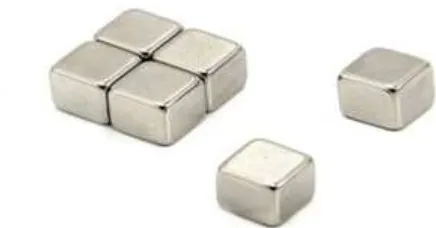
Fig. 1: Cubic shaped Neodymium magnets
Figure 1 shows Cubic shaped Neodymium magnets. Neodymium magnets are a member of the Rare Earth magnet family and are the most powerful permanent magnets in the world. They are also referred to as NdFeB magnets, or NIB, because they are composed mainly of Neodymium (Nd), Iron (Fe) and Boron (B). Neodymium magnets are over 10x stronger than the strongest ceramic magnets. Here we are using N52 grade high strength cubical shaped Neodymium magnets of size 30mm*20mm*10mm
Gear Blank:
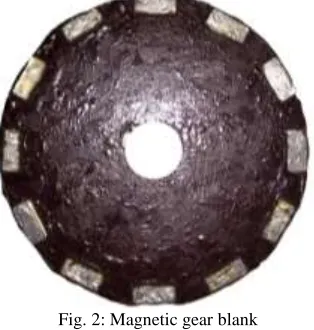
Fig. 2: Magnetic gear blank
Figure 2 shows the Magnetc gear blank made of hylam material and cubical shaped Neodymium magnets are placed inside the slots provided.
Shaft:
Two mild steel shafts of length 60cm and diameter varying from 24mm to 17mm as per shaft design. Both of the shafts are supported by two roller bearings of inner diameter 17mm and 24mm and outer diameter of 35mm and 42mm respectively. The centre to centre distance between two shafts is 143mm. The prime mover is connected to the upper shaft with the help of a coupling. The upper shaft being the input shaft the gear blanks are kept fixed by providing keys. The lower shaft being the output shaft the gear blanks are movable to show variable gear ratios. Metal bushes are used to fix the gear blanks at required positions on the lower shaft.
Base:
Base consists of two upper and lower compressed wood supports for the stability of the prototype. Two vertical post of compressed wood itself are provided to place the two mild steel shafts. On the left post two bearing seats of inner diameter 42mm and outer diameter of 52mm are there at a distance of 143mm for placing the 24mm bearings.
teeth. Some mechanical gears are very similar to magnetic gears for instance the magnetic spur gear.
Fig. 4: Magnetic spur gear with magnets and mechanical spur gear.
Figure 4 shows the similarity between a Magnetic spur gear and the conventional toothed gear. Magnetic spur gear consists of magnets arranged circumferentially and the alternate attraction and repulsion helps in power transmission .
Fig. 5: 3-D Model of gear blanks
Figure 5 shows the 3-D model of the proposed Mgnetic gear. The traditional mechanical gear uses steel teeth’s to transfer torque. Gear wheel teeth have physically contact with each other, and there will be wearing on the tooth flanges. The magnetic gear does not have the same wear, because there is no direct contact. Permanent magnets on the gearing wheels transfer the torque between the two wheels. Since the magnetic gear does not have direct contact, there will be a fictive torsion spring effect between gear wheels.
Fig. 6: A magnetic gear and a torque diagram.
Figure 6 shows the torque diagram of the Magnetic gear. Gearing relationship Rg depends on the number of magnets Npole1 on the drive wheel and Npole2 on driven wheel. This relationship can be shown as equation (1).
Most gear systems have a gearing relationship Rg which is greater than one, which corresponds to high revolutions on the input shaft and low revolutions on the output shaft. Gearing relationship equation is valid for mechanical gears also if the number of magnet poles are replaced of number of teeth’s on each gearing wheel.
Rg= Npole1
Npole2 (1)
V. DESIGN OF MAGNETIC GEARING SYSTEM
Mathematical Modeling Of Magnetic Gear With Cuboidal Magnets:
Two cubical magnets of sides a, b, and c and a0, b0, and c0 are shown in Figure 7.
Fig. 7: Cuboidal magnets: (a) front view and (b) sectional side view
za is the axial offset between the magnets. The vertical force (Fy,c) between two cubical magnets shown in figure 7 is estimated using Coulombian equation is represented in the following equation:
Fy,c= σ1σ2
4πμ0(R(Za) + R(Za+ H − B) + R(Za+ H) + R(Za− B)) … (2)
Where
R(α) = ∫ ∫ ∫ ∫ (Clc+Y−y)
((φ+X−x)2+(Clc+Y−y)2+(Za+Z−z)2)1.5dXdYdxdy
a′ 0 b′ 0 a 0 b
0 … (3)
The vertical force between two cubical magnets is found by using Eq. (2)
Fy,c=
σ1σ2
4πμ0
(R(0) + R(0.01 − 0.01) + R(0.01) + R(−0.01))
Where
R(α) = ∫ ∫ ∫ ∫ (Y − y)
((X − x)2+ (Y − y)2+ (α)2)1.5dXdYdxdy 0.01
0 0.01
0 0.01
0 0.021
0.001
The value of Fy,cis estimated by solving the above equation in MATLAB and found to be 66.016 N.
66 N is sufficient for driving the whole gear system so we confirmed 3mm as the distance between two gear blanks Distance Between Two Gear Blanks On Same Shaft:
By analysing the magnetic field visualization and the magnetic vector plot from the 3D magnetic gear model, The magnetic field lines are concentrated only at the two sides of the cubical magnet and it has been recorded that the range of magnetic field is below 10 cm hence two magnets can be kept at a distance of 10 cm without having flux linkages. By the help of this practical calculation we kept the two gear blanks on a single shaft at a distance of 10 cm apart.
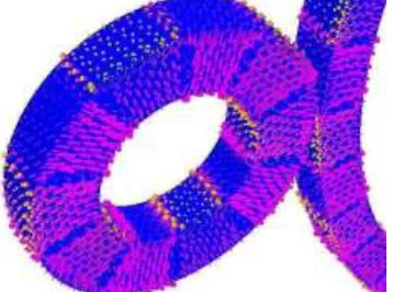
Fig. 8.2: B-field vector plot from the 3D magnetic gear model.
Figure 8.2 shows the magnetic field vector plot diagram which shows the direction of the magnetic field lines. Figure 8.3(a) shows the magnetic field visualisation which shows the strength of the cubical magnet we are using. Figure 8.3(b) shows the pull force generated by two magnets and its variation according to the distance between them changes.
Gear Ratios:
The prime mover motor is kept at 1000 rpm so the input shaft rotates at same speed. In order to decease and increase the output speed at our desired level we have to design the diameter and the number of magnets of meshing gears.
Ninput
Noutput
=Doutput Dinput 1st gear
Input speed =1000 rpm
Diameter of gear in input shaft = 80mm Diameter of shaft in output shaft = 200mm
1000 𝑁𝑜𝑢𝑡𝑝𝑢𝑡
=200
80 𝑁𝑜𝑢𝑡𝑝𝑢𝑡= 400 rpm
Output speed = 400rpm 2nd gear
Input speed =1000 rpm
Diameter of gear in input shaft = 180mm Diameter of shaft in output shaft = 100mm
1000 Noutput
=180
100 Noutput= 555.5 rpm
Output speed = 555.5rpm 3rd gear
Input speed =1000 rpm
Diameter of gear in input shaft = 200mm Diameter of shaft in output shaft = 80mm
1000 Noutput
= 80
200 Noutput= 2500 rpm
Output speed = 2500rpm Scope for Future:
Magnetic gears are becoming competitive alternatives to conventional gears. They present no contact and no wear. They do not produce debris and they do not require lubricant, being able to be operated at abroad range of temperature ranging from -270ºC up to 350ºC. They present intrinsic anti-jamming properties and there is a clutching effect if the applied torque exceeds a limit therefore protecting the output from overloads. This effect is completely reversible without any damage or wear.
This technology is currently increasing making it available for consideration for aerospace uses. The radically different behaviour against torque overloads, the isolation of vibrations, the absence of maintenance, the compatibility with sand or dust, broad temperature range and the through wall capability are some properties that make these devices attractive for aerospace and other future applications
VI. APPLICATIONS OF MAGNETIC GEARS
Turbine Generators:
- Key drivers: reduce weight + increase reliability - Non-contact gearbox or integrated gearbox / generator - Reduce direct drive diameter
Aerospace:
- The isolation of vibrations - The absence of maintenance - Broad temperature range
VII.CONCLUSION
Magnetic gears afford the opportunity to provide speed and torque multiplication similar to a traditional geared gearbox or transmission, but by using magnetic attraction between rotating members rather than actual physical contact, as between gear teeth. It may be possible to greatly reduce, or potentially eliminate, lubrication requirements, compared to existing traditional gearboxes.
A magnetic gear based gearbox for winch applications could increase reliability and mission availability by reducing or perhaps eliminating wear-related gearbox failures attributable to traditional tooth-to-tooth contact.
ACKNOWLEDGEMENT
First and foremost, we express our heartfelt gratitude to our guide, Er. Davis Wilson , Assistant Professor, Department of Mechanical Engineering, Saintgits college of Enigineering for his valuable guidance, support and encouragement. Help rendered by Dr. Sreejith C C, Er. Vineeth V K, Er. Bibin Varkey and all other staff members of the Department of Mechanical Engineering, Saintgits college of Engineering are thankfully acknowledged. We also remember with thanks all our friends and well-wishers for their encouragement and support.
REFERENCES
[1] K.T. Chau, M. Cheng1 and W. Hua ,X. Li “Comparison of magnetic-geared permanent magnetic machines” Journal on Electromagnetics Research, Vol.
133,177{198, 2013}
[2] Chunhua Liu, Dong Zhang, J. Z. Jiang, K. T. Chau1 and Yuejin Zhang “Design of a magnetic-geared outer-rotor permanent-magnet brushless motor for