doi:10.3926/jiem.2009.v2n2.p407-417 ©© JIEM, 2009 – 2(2): 407-417 - ISSN: 2013-0953
Simulation of wind power with front-end converter into interconnected grid system
Simulation of wind power with front-end converter into
interconnected grid system
Sharad W. Mohod
1; Mohan V. Aware
21
Meghe Institute of Technology & Research, Badnera-(INDIA);
2Visvesvaraya National Institute of Technology Nagpur-(INDIA)
;
Received May 2009 Accepted July 2009
Abstract:
In the growing electricity supply industry and open access market for electricity
worldwide, renewable sources are getting added into the grid system. This affects the grid
power quality. To assess the impact on grid due to wind energy integration, the knowledge
of electrical characteristic of wind turbine and associated control equipments are required.
The paper presents a simulation set-up for wind turbine in MATLAB / SIMULINK, with
front end converter and interconnected system. The presented control scheme provides
the wind power flow to the grid through a converter. The injected power in the system at
the point of common coupling is ensured within the power quality norms.
Keywords:
power quality, wind generating system
1 Introduction
Generation of electricity from wind is the fastest growing energy technology in the world. India is in the 4th rank and has a renewable energy gross potential installed
doi:10.3926/jiem.2009.v2n2.p407-417 ©© JIEM, 2009 – 2(2): 407-417 - ISSN: 2013-0953
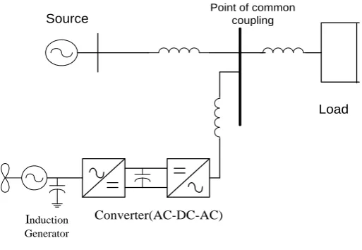
operation in electric power system, it is necessary to utilize the steady state model for analysis, related to load flow, short circuit calculation, power quality assessments, etc. The electric utility grid system cannot accept connection of new generation plant without strict condition, due to the real power fluctuation and reactive power generation of wind plants. Therefore the penetration of wind power in grid implies taking care of power quality issues like voltage variation on grid, switching operation of wind turbine (Reid, 1996). Today grid connected wind turbines are equipped with power converter systems. The wind–generation system interconnected with power system as shown in Figure 1.
Point of common coupling Source
Converter(AC-DC-AC)
Load
Induction Generator
Figure 1. “Wind –Generation system Interconnection with power system”.
doi:10.3926/jiem.2009.v2n2.p407-417 ©© JIEM, 2009 – 2(2): 407-417 - ISSN: 2013-0953
Simulation of wind power with front-end converter into interconnected grid system
2 Model of wind turbine
The static characteristic of wind turbine can be described by the relation between total power in the wind and mechanical power of wind turbine as in Equation 1. It presents a basic model for wind turbine in electric power system.
3 2
2
1
wind
wind
R
V
P
(1)In wind power Equation 1, where ρ- air density (1.225 Kg/ m3), R is rotor radius in
meters, Vwind is the wind speed in mtr3/sec.
It is not possible to extract all kinetic energy of wind, thus it is extracted a fraction of power in wind as given in Equation 2 and it is called power coefficient Cpof the wind turbine.
mech p wind
P
C P
(2)Pmech is the mechanical power of wind turbine in Nm/s. The power coefficient is
given as 0.59
27 16
p
C . This coefficient is also known as Betz’s limit. This coefficient
can be expressed as a function of tip speed ratio-λ and pitch angle-θ. The torque Tmax can be conveniently calculated from power Pmech by using turbine rotational
speed ωturbine.
turbine mech
mech
P
T
/
(3)Therefore,
)
,
(
turbine windmech
f
V
P
(4)p wind
mech
R
V
C
P
2 32
1
(5)The tip speed ratio λ is defined as Equation 6.
wind turbine
R
/
V
doi:10.3926/jiem.2009.v2n2.p407-417 ©© JIEM, 2009 – 2(2): 407-417 - ISSN: 2013-0953
Assuming constant wind speed Vwind, the tips speed ratio λ will vary proportionally
to the rotational speed of wind turbine rotor (Tande, 2002). The highest value of Cp
is typically obtained for λ values in the range of 8 to 9 (when the tip of the blades moves 8 to 9 times faster than incoming wind). On modern wind turbines, it is possible to adjust the pitch angle of the entire blade through servo mechanism (Jorgensen et al., 1997; Charly, 2007). Assuming constant wind speed Vwind, the
tips speed ratio λ will vary proportionally to the rotational speed of wind turbine rotor.If Cp - λ curve is known for specific wind turbine with a turbine rotor radius R,
it is easy to construct the curve of Cpagainst rotational speed for any wind speed.
The Cp- λ curve is shown in Figure 2.
0.5
0.2 0.3 0.4
2 4 6 8
CP
Figure 2. “Cp – λ curve”.
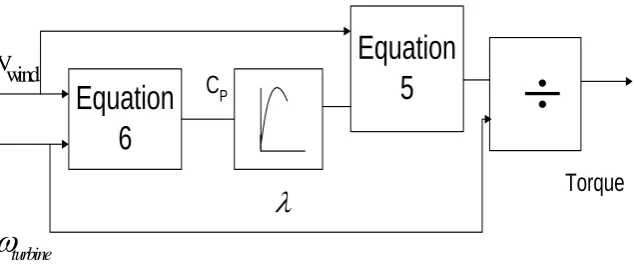
The wind turbine model is as fallows. The wind turbine model is constructed as shown in Figure 3, once the aerodynamic properties of wind turbine are described.
Equation
6
Equation
5
Vwind
turbine
Torque
C
P
doi:10.3926/jiem.2009.v2n2.p407-417 ©© JIEM, 2009 – 2(2): 407-417 - ISSN: 2013-0953
Simulation of wind power with front-end converter into interconnected grid system
Where Vwind and
turbine are input of Equation 6 in the block diagram and CP iscalculated and given as input for Equation 5, so as to get output power. This power is divided by
turbine to get output torque.3 Control strategy
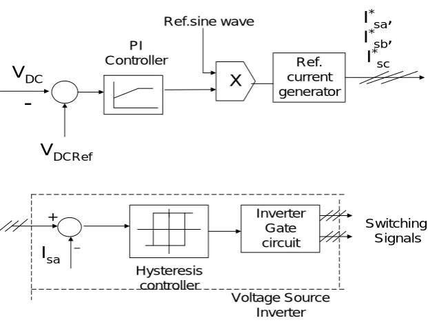
The control scheme block diagram for the simulation of power system on grid is shown in Figure 4. The dotted line is the voltage source inverter in current control mode.
Switching Signals Inverter
Gate circuit +
I
saHysteresis controller
_
Voltage Source Inverter
X
V
DCV
DCRef-PI Controller
Ref.sine wave
Ref. current generator
I
* sa,
I
*sb
,
I
*sc
Figure 4. “Control Scheme block diagram”.
In the simulation of wind-connected system on grid, the generator is connected to a rectifier. The output of this rectifier is connected to the dc bus. The dc bus voltage at which wind generating system is connected with a set reference values and error is sent into proportional and integral (PI) controller. In PI controller the proportional gain kp will reduce the rise time of error and the integral gain ki will
eliminate the effect of steady state error. The output of this controller is given to the multiplier circuit, where a reference sine wave generator multiplies the output of proportional integral PI controller and desired reference current I*
ref. is obtained.
doi:10.3926/jiem.2009.v2n2.p407-417 ©© JIEM, 2009 – 2(2): 407-417 - ISSN: 2013-0953
controller to generate the switching pattern (Mohod et al., 2006). Switching signals
are obtained by comparing reference currents *
sa
i
,i
sb* ,*
sc
i
with actual currentsi
sa,i
sb,
i
sc. Current errors
i
a,
i
b,
i
care applied to the hysteresis controllers producingthe correct signal to switch the power electronics switches ON and OFF. Therefore the reference current for the comparison must be derived from the source voltage. These currents can be expressed as Equation 7.
i
sa
I
sin(
t
)
,i
sb
I
sin(
t
120
0)
,i
sc
I
sin(
t
240
0)
(7)Where, I is proportional to the magnitude of the filtered source voltage of phase ‘a’. This ensures that the source current is controlled to be sinusoidal irrespective of whether the source voltage is unbalanced.
4 System for simulation
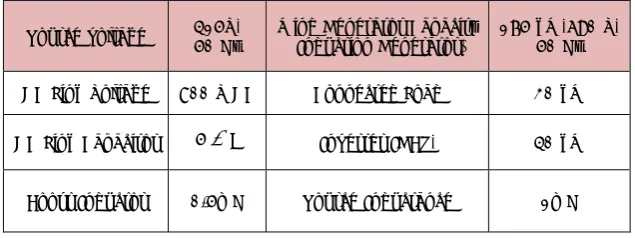
A grid connected wind turbine generating system is simulated in the SIMULINK using Power System Block set. The variable speed turbine with generator having similar wind characteristics is interfaced with the rectifier unit to get dc bus voltage and ac-dc-ac converter is interfaced to the grid. The system parameters are presented in the Table 1.
Source voltage 415V, 50 Hz Wind Generator Capacity (Induction Generator) 175 kW,690 V, 50 Hz
DC Link Voltage 800 V DC Connected Load 30 kW
DC Link Capacitor 5
F Inverter IGBT, 40 kWBoost Inductor 0.5mH Source Inductance 1mH
Table 1. “Simulation Parameters”.
5 System performance
doi:10.3926/jiem.2009.v2n2.p407-417 ©© JIEM, 2009 – 2(2): 407-417 - ISSN: 2013-0953
Simulation of wind power with front-end converter into interconnected grid system
5.1 Steady State Performance
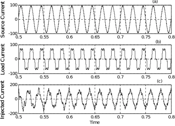
The result of source current at point of common coupling (PCC) is shown in Figure 5a and non linear load current is shown in Figure 5b. The injected current from the inverter is shown in Figure 5c.
Figure 5a. “Source Current”; 5b. “Load Current”; 5c. “Inverter Current”.
The source current is maintained sinusoidal and in phase with source voltage, indicating the unity power factor at PCC and shown in Figure 6.
Figure 6. “Source Voltage & Current at PCC”.
0.5 0.55 0.6 0.65 0.7 0.75 0.8 -100 0 100 So u rc e Cu rr e n t
0.5 0.55 0.6 0.65 0.7 0.75 0.8 -100 0 100 Loa d C u rr e n t
0.5 0.55 0.6 0.65 0.7 0.75 0.8 -200 0 200 Time In je c ted C u rr en t (a) (b) (c)
0 .5 0 .5 5 0 .6 0 .6 5 0 .7 0 .7 5 0 .8
- 5 0 0 - 4 0 0 - 3 0 0 - 2 0 0 - 1 0 0 0 1 0 0 2 0 0 3 0 0 4 0 0 5 0 0
doi:10.3926/jiem.2009.v2n2.p407-417 ©© JIEM, 2009 – 2(2): 407-417 - ISSN: 2013-0953
The active power, data 1 in Watt and reactive power flow, data 2 in Watt at the PCC is shown in Figure 7. The reactive power observed is zero, at PCC.
Figure 7. “Active and Reactive power at PCC”.
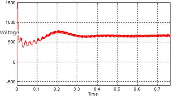
The generated output of wind turbine is rectified and connected to dc link and it is shown in Figure 8.
Figure 8. “DC Link Voltage”.
5.2 Performance under dynamic behavior of the system
doi:10.3926/jiem.2009.v2n2.p407-417 ©© JIEM, 2009 – 2(2): 407-417 - ISSN: 2013-0953
Simulation of wind power with front-end converter into interconnected grid system Figure 9a. “Load Current under dynamic behavior”.
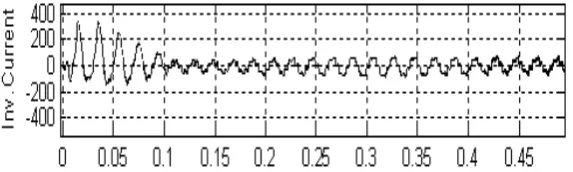
Figure 9b. “Inverter Current under dynamic behavior”.
It is observed that at any time the reactive power demand is supplied by inverter. The system makes unity power factor. The system can supply real power and can compensate for reactive power. Thus the simulated system improves grid power quality norm IEC standard 61400-21.
6 Conclusions
doi:10.3926/jiem.2009.v2n2.p407-417 ©© JIEM, 2009 – 2(2): 407-417 - ISSN: 2013-0953
References
Chen, Z., & Sprioner, E. (2001). Voltage Source Inverters for High Power, Variable Voltage DC Power Supply’. IEEE Proceeding Generation, Transmission and Distribution, 148(5), 419-447.
Ekanayake, J. B., & Holdsworth, L. (2003). Dynamic Modeling of Doubly fed Induction Generator Wind Turbines’. IEEE Transactions on Power System, 18(7), 803-810.
Lou, C., Banakar, H., & Shen, B. (2007). Strategies to smooth Wind Power Fluctuations of Wind Turbine Generator, IEEE Conference on Energy Conversion, 22, 341-349.
Jorgensen, P., & Tande, J. O. (1997). Power Quality and Grid Connection of Wind Turbines. IEEE Conference Publication, 438.
Kinjo, T., & Senjyu, T. (2006). Output Leveling of Renewable Energy by Electric Double Layer Capacitor Applied for Energy Storage System. IEEE Transaction on
Energy Conversion, 21(1).
Matlab (1995). MATLAB / SIMULINK user guide, Math Works inc. USA .
Matsuzaka, T., & Tsuchiya, K. (1997). Study on stabilization of a wind generation power fluctuation. T.IEE Jpn., 117-B(5) 625 – 633.
Mohod, S. W., & Aware, M. V. (2006). Grid Power Quality with Variable Speed Wind
Energy Conversion. Presented at the IEEE International Conference on Power
Electronic Drives and System (PEDES) Delhi.
Mohod, S. W., & Aware, M. V. (2007). Modeling and simulation of Grid Connected
Wind Turbine Generating System. Presented at the International Conference on
Power Systems (ICPS), Central Power Research Institute, Bangalore.
doi:10.3926/jiem.2009.v2n2.p407-417 ©© JIEM, 2009 – 2(2): 407-417 - ISSN: 2013-0953
Simulation of wind power with front-end converter into interconnected grid system
Reid, W. E.(1996). Power Quality Issues – Standards and Guidelines. IEEE
Transactions on Industry, 625-632.
Smith, J. C., & Milligan, M. R. (2007). Utility Wind Integration and Operating Impact State of Art. IEEE Transaction onPower System, 22(3), 900-910.
Tande, J. O. Q. (2002). Applying power quality characteristic of wind turbine for assessing impact on voltage quality. Wind Energy, 37-52.
©© Journal of Industrial Engineering and Management, 2009 (www.jiem.org)
Article's contents are provided on a Attribution-Non Commercial 3.0 Creative commons license. Readers are allowed to copy, distribute and communicate article's contents, provided the author's and Journal of Industrial Engineering and Management's names are included. It must not be used for commercial purposes. To see the complete