An Oracle White Paper November 2012
Oracle VM 3:
Integrating Oracle VM into a Disaster Recovery
Solution using SAN
Contents
Introduction ... 1
Part 1: Solution Architecture and Concepts ... 2
Installing and Configuring Oracle VM 3 ... 2
Existing Business Continuity Solution is a Requirement ... 2
Solution Flexibility ... 3
Flexibility through independent Oracle VM Managers ... 3
Flexibility through independent server pools ... 3
Flexible active/standby solutions with a single server pool at one site4 Flexible active/active solutions with a single server pool at each site 4 Flexible active/active solutions with multiple server pools at each site5 Flexible hybrid solutions including non-DR server pools ... 6
Key concepts ... 7
Overview of the Active/Standby Example Used in this Paper ... 7
Site Considerations ... 9
Required Hardware ... 9
Homogeneous Vs. heterogeneous hardware between sites ... 9
Network Considerations ... 11
Global Network Name Space ... 11
Oracle VM Network IDs ... 12
Using network metafiles to sync Oracle VM network IDs ... 13
Revealing Oracle VM network IDs ... 15
Virtual NICs ... 16
Storage Considerations ... 16
Pool file system ... 16
Physical disks ... 16
Storage repositories ... 16
Virtual disks ... 17
Data Replication Software... 17
Triggering a DR Failover ... 18
Develop Meaningful Conventions ... 18
Oracle VM Version Considerations ... 19
Product Licensing ... 19
Conclusion... 19
Part 2: Integrating Oracle VM into a DR Environment ... 20
Process Overview ... 20
Before Beginning the Installation and Configuration Process ... 21
Servers for Site B ... 21
Storage for Site B ... 21
Pool file system ... 22
Storage repository ... 22
Oracle VM Guests for validation ... 22
Step 1: Install and Configure Oracle VM at Site A ... 22
Step 2: Install Oracle VM Servers at Site B ... 22
Step 2.1: Install Oracle VM Server on Site B servers ... 23
Step 3: Replicate Site A Network IDs to Site B ... 23
Step 3.1: Determine which metafiles to copy... 23
Step 3.1: Copy the metafiles to Site B Oracle VM Servers ... 24
Step 4: Install Oracle VM Manager at Site B ... 24
Step 4.1: Get the UUID of the Site A Oracle VM Manager ... 25
Step 4.2: Install Site B Oracle VM Manager using Site A UUID ... 25
Step 5: Discover Oracle VM Servers at Site B ... 26
Step 6: Configure network interfaces for Site B ... 26
Step 6.1: Ensure all Ethernet interfaces are available ... 26
Step 6.2: Configure bonded interfaces ... 27
Step 6.3: Create VNICs for Site B ... 27
Step 7: Configure Oracle VM management networks ... 27
Step 8: Configure Oracle VM Guest networks ... 28 Step 8.1: Remove the virtual machine channel from each network . 29
Step 8.2: Add the virtual machine channel to each network ... 29
Step 8.3: Finish adjusting any other networks ... 30
Step 9: Register Storage at Site B ... 30
Step 10: Create Server Pool at Site B ... 31
Step 11: Validate Server Pool at Site B ... 31
Step 12: Implement Storage Replication between Sites... 31
Conclusion... 32
Part 3: Executing a Failover from Site A to Site B ... 33
The Process Flow ... 33
Step 1: Prepare Site A for failover ... 34
Step 2: Present replicated storage to Oracle VM Servers ... 34
Step 3: Discover replicated storage on Oracle VM Servers ... 34
Step 3.1: Rescan for disks on Oracle VM Servers ... 34
Step 3.2: Add the Site A repository to the Site B OCFS2 cluster ... 36
Step 3.3: Refresh the disk containing the storage repository ... 37
Step 4: Present replicated storage repository ... 38
Step 5: Ensure networking is correct for Oracle VM Guests ... 39
Step 6: Ensure storage is correct for Oracle VM Guests ... 39
Step 7: Start Oracle VM Guests on Site B servers ... 39
Step 7.1: Migrate Oracle VM Guests ... 39
Step 7.2: Start Oracle VM Guests ... 40
Conclusion... 40
References ... 41
Pertinent Oracle white papers ... 41
Book references ... 41
Introduction
Oracle offers a complete product portfolio that includes applications, middleware, database, operating systems, servers, storage, and even thin clients — along with across the stack
virtualization and clustering technologies that are optimized to work together. Oracle VM 3 is simply one piece of a very complex puzzle that must be integrated along with other disaster recovery software and applications into an overall business continuity solution for your enterprise. This technical white paper focuses on Oracle VM Server for x86, explains how to incorporate Oracle VM 3.1.1 into an existing or planned disaster recovery solution in your data center.
The solution presented in this paper is designed to use Fibre Channel (FCP) or iSCSI SAN storage as the protocol being used to present physical disks to the server pools for storage repositories, applications and application data. Either SAN or NAS (NFS) can be used to integrate Oracle VM into multisite disaster recovery solution, but only SAN (FCP or iSCSI) is discussed in this paper. The decision regarding which SAN storage protocol to use is completely dependent on the storage infrastructure available in your particular data center.
Our goal is to provide knowledge and insights into Oracle VM that will help you design a solution that fits with the unique requirements of your software and hardware platform. This paper assumes the reader is knowledgeable and experienced with Oracle VM 3, data replication, business continuance and disaster recovery concepts. Topics such as high availability, data replication, backup and recovery strategies are beyond the scope of this document since computing environments and business continuity strategies vary so widely in approach and complexity.
This paper is divided into three parts. The first part explains the architecture and design considerations for storage, network and product installation. The second part of the paper explains in detail how to prepare and install Oracle VM 3 for an active/standby solution using SAN. The third part of the document explains in detail how to execute a failover from the active site to a standby site.
Part 1: Solution Architecture and Concepts
Oracle VM presents a disaster recovery solution that is flexible enough to allow easy integration with the varying degrees of complexity and technologies used in today’s data center to build computing environments for business systems. There is no single approach or method for designing a mission critical disaster recovery solution presented in this paper since every data center environment is going to be slightly different: different servers, different backup solutions, different storage vendors, unique networking infrastructures, different application stacks, etc. Oracle VM provides the tools needed to adapt the product to your particular environment.
The solution presented in this white paper includes some step-by-step instructions that must be followed in order to integrate Oracle VM into an overall disaster recovery project under any circumstance, but the examples and screen shots are simple in nature and are not representative of a robust network or storage solution. This document is meant as a guideline rather than rigid
instructions for designing and implementing your mission critical Oracle VM deployment: you must take the information presented here and adapt it to fit your unique requirements.
Installing and Configuring Oracle VM 3
Setting up and configuring Oracle VM 3 server pools is beyond the scope or purpose of this document. Please use the Getting Started guide that is an integral part of the Oracle VM Manager interface to learn how to configure an Oracle VM server pool with Oracle VM Guests. You should not attempt to integrate Oracle VM into a disaster recovery solution if not already very familiar with installing, configuring and managing Oracle VM. Important user guides for getting started with Oracle VM can be found on Oracle Technology Network for Oracle VM documentation.
Existing Business Continuity Solution is a Requirement
Oracle VM is simply a small piece of a complete business continuity structure. All other aspects of a disaster recovery solution are assumed to be in place before integrating Oracle VM into the overall architecture. At the very least the following components of a complete business continuity solution should be in place:
A proven method for backing up and recovering Oracle VM Servers
A proven method for backing up and recovering Oracle VM Manager & storage repositories A proven method for backing up and recovering applications and data within the Oracle VM
environment
A proven method for replicating Oracle VM storage repositories, applications and data between sites A proven fault tolerant, highly available computing environment needs to be in place. The goal is to
eliminate single points of failure for power, networking, servers, storage and applications at each site. A plan for continuous maintenance and site synchronization for the overall solution
Solution Flexibility
Oracle VM 3 is flexible enough to be integrated into almost any DR solution envisioned by Oracle customers. As indicated in the introduction, Oracle VM is only a small piece of a complete business continuity solution. Each hardware and software vendor will have solutions, user guides and technical white papers explaining how integrate their particular products into an overall disaster recovery plan. Figure 1 below illustrates some of the basic building blocks for a complete DR plan.
Figure 1: Oracle VM is just one of many pieces needed to build a complete DR solution
Oracle VM is flexible enough that it can be adapted to a wide variety of DR solutions. We provide an example throughout this document using a simple two site, active/standby solution with a server pool at each site, but there are many possible solutions that go far beyond our example. Using the
information provided in this paper, the same concepts for the active/standby solution can easily be adapted to create any number of active/active or active/standby scenarios – imagination is the only limitation to potential solutions.
Flexibility through independent Oracle VM Managers
No matter which type of solution you choose, whether it is a variation of the active/standby presented in this paper or active/active coverage, the key to integrating Oracle VM 3 into a multisite disaster recovery plan is ensuring each site has a completely independent instance of Oracle VM Manager. Maintaining independent Oracle VM Managers is a key point since it means everything about the two sites can be completely different; different number of server pools, different number of servers, different server models, different network infrastructure, different storage infrastructure, etc. Independent Oracle VM Managers allow maximum flexibility in the way each site is configured. Having separate Oracle VM Managers means that the database maintained by Oracle VM Manager at Site A is never replicated to Site B or vise versa.
Flexibility through independent server pools
Since the Oracle VM Managers at each site are independent of each other, it follows that the pool file systems for each server pool are also independent. Pool file systems are not replicated for any of the
Oracle VM DR solution Application DR solution Storage DR solution Backup DR solution Network DR solution Service level agreements DR training, validation & audit
A Complete Business Continuity Solution
DR solutions discussed in this paper since the data contained in a pool file system are relevant only to the servers and storage belonging to a particular server pool.
Not replicating server pool file systems gives you the flexibility to make each server pool at each site completely different. This opens many possibilities for more cost effective hardware solutions between sites and gives you the flexibility to design each site any way that fits your requirements.
Flexible active/standby solutions with a single server pool at one site
We briefly touch on a few different conceptual DR solutions in this section of the paper to provide a glimpse of the many possible ways the Oracle VM Manager can be used at each site. The
active/standby solution shown in Figure 2 below is one of many possible solutions, but it is the only scenario we explain in detail and use as an example throughout this paper.
Figure 2: Overview of an active/standby disaster recovery scenario
Figure 2 shows a primary (active) server pool at Site A and a recovery (standby) server pool at Site B. The Site B server pool has running Oracle VM Servers, but no running Oracle VM Guests – the servers are standing by waiting for a site failover before any Oracle VM Guests from Site A are imported and started at Site B. You need to devise a periodic disk/data replication process to replicate only the Site A storage repositories and physical SAN disks containing applications and application data from Site A to Site B. The replicated storage at Site B is not made available to the Site B server pool until after a failure of Site A.
Flexible active/active solutions with a single server pool at each site
Although we do not specifically explain an active/active multi-site solution in this document, one can be achieved by simply applying the same process shown in this white paper in reverse. Figure 3 describes an active/active solution with a single server pool, yet four server pools can be seen which may be a little confusing. To be clear, this is because each site has a single active server pool with a corresponding standby server pool at each of the sites. In this scenario, Site B acts as a recovery site for Site A and Site A acts as a recovery site for Site B. Note that the only difference between the
active/standby and active/active illustrations in Figure 2 and Figure 3 below is the additional arrow showing the storage replication from Site A to Site B as well as from Site B to Site A.
Figure 3: Overview of an active/active disaster recovery scenario
In this scenario, both Site A and B have primary server pools with actively running Oracle VM Guests. Each site also has a matching standby server pool waiting to take over running guests from its sister site. For example, Figure 3 shows that the primary Server Pool 1 is active at Site A with a standby Server Pool 1 at Site B. It also shows a primary Server Pool 2 is active as Site B with a corresponding standby Server Pool 2 at Site A.
This solution also requires you to devise a periodic disk/data replication process to replicate the Site A storage repositories and physical SAN disks containing applications and application data from Site A to Site B. But you also need to devise a periodic disk/data replication process to replicate the storage repositories and data disks from Site B to Site A. The replicated storage from either site is not made available to the matching standby server pool until after a failure has occurred at one site or the other.
Flexible active/active solutions with multiple server pools at each site
Oracle VM is flexible enough to implement an active/active disaster recovery solution with multiple server pools at each site as illustrated in Figure 4 below. You can also choose a subset of server pools from either site. For example, perhaps only two server pools at Site A are replicated to Site B and only one server pool from Site B is replicated to Site A. Imagination is the only real limitation to the possible combinations of solutions when integrating Oracle VM into a disaster recovery solution.
Figure 4: Overview of an active/active scenario with multiple server pools
Flexible hybrid solutions including non-DR server pools
In the final example shown in Figure 5, we illustrate an active/active scenario that incorporates server pools that are part of a DR solution and two server pools that are not part of a DR solution at all. The illustration is identical to the one shown in Figure 4, except in this case we show Server Pool 4 and Server Pool 5 are not part of the DR solution. The Oracle VM Manager at each site can manage active server pools that are part of a DR solution as well as server pools that are not part of a DR solution
Figure 5: Overview of an active/active scenario with multiple server pools including some that are not part of a DR solution
Key concepts
Now that we’ve introduced a few different architectural possibilities for you to consider, it is time to introduce some key concepts that will require much deeper understanding to successfully integrate Oracle VM into a disaster recovery solution. Some of the listed concepts have already been mentioned briefly while others have not been discussed yet. In either case, each of the following concepts will be explained in much more detail and should become clearer as you continue to progress through the paper.
Independent Oracle VM Managers. All Oracle VM Managers should be completely independent of each
other. Therefore the databases for each manager are not replicated.
Oracle VM Manager UUID. The Site B Oracle VM Manager must be installed using the same UUID
as the Site A Oracle VM Manager. This allows the Site B Manager to use the replicated storage repository that is owned by the Site A Manager.
Independent server pools. All server pools should be completely independent of each other. Therefore the pool file systems for each site are not replicated.
Storage replication. Only the storage repositories and disks containing applications and application data are replicated between sites.
Disk World Wide IDs. World Wide IDs for disks must be the same at both sites. Not to be confused
with Fibre Channel World Wide Node or Port Names, the physical disks at Site B must have the same exact WWID as they do on Site A so the Site A guests can find the same disks when they start on Site B.
Global network name space. The solution assumes that both Site A and Site B have exactly the same network infrastructures for the virtual machine network channels.
Virtual machine network IDs. Virtual machine network IDs must be exactly the same at both sites.
Overview of the Active/Standby Example Used in this Paper
We now introduce you to the fictional active/standby example used throughout the remainder of this document which we use to help illustrate concepts and processes in the remainder of this white paper. Figure 6 below shows a graphic depiction of our example scenario. Let’s use the diagram shown in Figure 6 help explain a few of the key concepts from the previous subsection.
Independent Oracle VM Managers. The diagram is divided into a primary site (Site A) and a standby site (Site B). Each site has a completely independent Oracle VM Manager with a completely independent database. You will want to create a daily backup of each database, but do not include either of the databases into the DR data/disk replication scheme. This will be explained in more detail as you progress through the remainder of this document.
Oracle VM Manager UUID. Notice that the top of the diagram indicates that the Managers at both
are installed using the same UUID. As indicated in the previous subsection, the duplicate UUIDs allow the Site B Manager to use the replicated storage repository that is owned by the Site A
Manager. We explain how to install the Site B Manager so it has the same UUID as the Oracle VM Manager at Site A in part 2 of this document.
Figure 6: Example scenario used in this white paper
Independent server pools. The diagram also shows a server pool at the primary site called Site A mypool1. This server pool contains two Oracle VM Servers named myserver1 and myserver2; the servers are actively running Oracle VM Guests. The standby site has a server pool called Site B mypool1. This server pool contains two completely different Oracle VM Servers called myserver3 and myserver4. Unlike the Site A server pool, Site B mypool1 is not running any Oracle VM Guests at all.
As described previously, all server pools should be completely independent of each other. Therefore the pool file systems for each site are not part of any data/disk replication scheme. This concept is further explained in Storage Considerations in Part 1 of this document.
Storage replication. It’s recommended to use storage replication solutions from your storage vendor or Oracle products such as Data Guard. Both of these solutions are beyond the scope of this
document.
Notice the lower part of the diagram in Figure 6 shows a representation of a storage array and the LUNs/disks contained on each storage array that need to be part of the data/disk replication scheme. One array is located at the primary Site A and another storage array is located at the standby Site B; the arrays in our example are physically independent of each other. The storage arrays depicted in the diagram can be Oracle ZFS appliances or a vendor platform of your choice.
The green arrows indicate the disks/LUNs that should be part of a data/disk replication scheme for your DR solution. Only the storage repositories and disks containing applications and application data are replicated between sites. The pool file system should not be replicated to the standby site. This concept is further explained in Storage Considerations in Part 1 of this document.
Disk World Wide IDs. World Wide IDs for disks must be the same at both sites. This is not specifically shown in the diagram but is further explained in Storage Considerations in Part 1 of this document.
Global network name space. The yellow box at the bottom of the diagram is a very important concept, but is only applicable to Oracle VM networks that have been assigned a Virtual Machine channel role; the solution assumes that both Site A and Site B have exactly the same network infrastructures for the virtual machine network channels. This is also explained in much greater detail in Network Considerations.
Virtual machine network IDs. Virtual machine network IDs must be exactly the same at both sites. This concept is closely related to the requirement for a global network name space. We devote quite a lot of attention to explaining both the global network namespace concept and network IDs in
Network Considerations in Part 1 of this document.
Site Considerations
We begin our more in-depth explanation of key concepts with this section by discussing a few critical concepts that need to be understood about the disaster recovery sites, assuming a primary site (Site A) and a recovery site (Site B). The ability to extend the DR integration to more than two sites is entirely possible, but a two site solution is a very common solution so the discussion in this document is limited to a two sites.
Required Hardware
The solution presented in this white paper does not depend on any particular hardware solution. Oracle customers can use any supported hardware platform and storage vendor that fulfills the requirements for their unique business system.
Homogeneous Vs. heterogeneous hardware between sites
For best performance and higher availability, Oracle recommends that the hardware platform be identical at both sites for an Active/Standby or Active/Active business continuity model. This ensures that the disaster recovery site will be sized correctly to avoid unexpected results from Oracle VM Guests not being able to start at Site B due to fewer compute resources being available such as available memory, CPUs, differing network capacities, etc.
Figure 7 below shows a homogeneous solution where the server models, memory, CPUs, storage, storage capacity are identical at both sites. The advantage is that the recovery site can be counted on to handle whatever the primary site is managing in the event of a failover. The disadvantage is that it is harder to maintain consistency between sites over time.
Figure 7: Homogeneous solution with storage and servers being the same at each site
On the other hand, Figure 8 below shows a more heterogeneous solution where one site can have more or less hardware resources with completely different server models, different memory, CPU, network and storage capacity. The advantage to this paradigm is that data centers can utilize existing equipment or find less costly solutions for either the primary or recovery site. In fact, one of the primary benefits of virtualized guest operating system is hardware independence. Basically, each site can be built using servers and storage from entirely different manufacturers.
The obvious disadvantage to using a heterogeneous solution is that there is a distinct possibility that the recovery site may not have the resources of the primary site and some Oracle VM Guests fail to start on the recovery site due to computing resources being wholly utilized by the first few Oracle VM Guests that are able to start after a failover. In addition, particular attention must be paid to the storage replication software when using different storage vendors at each site. Data replication requirements are examined in more detail in the Storage Considerations section of this white paper.
Figure 8: Heterogeneous solution with storage and servers being different at each site
Oracle VM 3 allows quite a bit of latitude when it comes to architecting complex solutions that fit the requirements and capabilities of global or independent data center operations.
Network Considerations
Networking and storage are the most important pieces of the integration process as well as the most challenging to understand. So, this white paper devotes a little more space explaining
networking and storage concepts in the hope that some of the tasks in Part 2 make a little more sense.
Global Network Name Space
The single most problematic issue in any disaster recovery solution is
the network configuration for the Oracle VM guest operating systems as well as the applications and databases that run within the guest operating systems. Oracle VM can certainly be configured to start all the Oracle VM Guests at the recovery site, but this is completely useless if the guest operating systems and applications cannot be reached when everything is up and running at the recovery site due to fact that everything is configured for the Site A broadcast domain if the Site B broadcast domain is completely different.
Therefore, the solution presented in this paper assumes a global network name space across both data centers as a requirement. The same exact IP addresses, subnet, gateways and host names for the guest operating systems need to be available in both the primary and recovery sites. Such global software designed networking solutions are becoming more and more prevalent since they greatly simplify the
!
Critical Concept!Understanding constraints imposed by Oracle VM network IDs is critical to the success of the integration effort – do not skip this section to save time.
deployment of applications on a worldwide scale for organizations using a unification or coordination type operational model.
If the overall disaster recovery solution you have designed includes software products that obviate the need for a global network name space, then each site can have completely different broadcast domains. However, you will need to define and build a solution to change the network configuration for each guest operating system since the replicated guests will still have a network configuration relevant only to Site A; designing and automating such a solution is beyond the scope of this white paper.
Oracle VM Network IDs
One very important aspect of networking that needs to be accomplished for any DR solution with Oracle VM is ensuring that the Oracle VM network IDs for any networks with the Virtual Machine Channel assigned are exactly the same at both Site A and Site B. The method for making the network IDs match at both sites is discussed in detail in Part 2 of this paper. This section explains why the network IDs need to match.
The “user friendly” simple names are inconsequential and can be quite different at both sites without any impact what-so-ever (note the different network names in boxes 1 & 4 in Figure 9 below). However, there is a direct relationship between the network ID shown in Oracle VM Manager and a Xen Bridge on the Oracle VM Servers. This is very important.
Xen bridges are only created and associated with network devices on the Oracle VM Servers for Oracle VM networks with the Virtual Machine Channel selected in the Oracle VM Manager. It is
imperative that the IP range, netmask, IP assignment and Oracle VM network ID be the same at both Site A and Site B for these virtual machine networks.
Figure 9: Network IDs must be the same at both sites for virtual machine networks
Using Figure 9 as an example, any Oracle VM networks enclosed in boxes 2 or 5 will have a corresponding Xen bridge on each Oracle VM Server while those Oracle VM networks enclosed in boxes 3 and 6 will not have a corresponding Xen bridge since bridges are only needed for network traffic between the network devices on Oracle VM Servers and Oracle VM Guests. However, the network IDs for the virtual machine networks must be exactly the same at both sites as shown in boxes 2 and 5. If the IDs are not the same, then the Site A Oracle VM Guests will not know which Oracle VM networks to use when they are running on Site B after a failover.
All other networks related to Oracle VM servers for the management of server pools can be completely different at both sites since each site has its own server pool with completely different servers and storage.
Using network metafiles to sync Oracle VM network IDs
The exact steps needed to make the network ID match at each site are articulated in Part 2 of this paper. However, the simple concept is to copy the Oracle VM network device metafiles from one of the Site A Oracle VM Servers to each of the Site B Oracle VM Servers before they are discovered by the Site B Oracle VM Manager. The diagram shown in Figure 10 on the next page illustrates the relationship between the network ID, the Xen bridges and the metafiles that define the network ID. The commands shown in Figure 10 are only examples to help illustrate general concepts and are not actually used at this point. You will need to understand the basis of this relationship to determine which network metafiles to copy from Site A to Site B during the initial installation and configuration of Site B – the actual steps are written in Part 2 of this document.
The metafiles reside in /etc/sysconfig/network-scripts on the Oracle VM Servers. The files contain the network ID for each Oracle VM network device which will be used during the server discovery process at Site B to create the matching Xen bridges using the same network IDs. These files must not be changed or edited by hand.
The example shown on the next page assumes that VLAN segments are being used for your solution. You will need to adjust if your particular solution does not use VLAN segments, or the VLAN segments are assigned to some other bonds or ports – the point is that you will need to determine the appropriate metafiles that fit your unique environment.
Figure 10 is comprised of four different diagrams showing how to logically connect the network ID from the Oracle VM Manager to the appropriate metafile. The top diagram shows a logical
representation of the network devices that exist for the example screen shots network traffic flows from the left of the diagram through a series of logical network devices to Oracle VM guests on the right side. This diagram shows the Xen bridges (1) that are created when the virtual machine channel is assigned to a network in Oracle VM Manager.
The second diagram is a screen shot of the Oracle VM Manager networking tab showing the network ID associated with each virtual machine enabled network. There is a direct relationship between the network ID (2) in the Oracle VM Manager UI and the Xen bridge for guest traffic shown in (1) on the Oracle VM Servers.
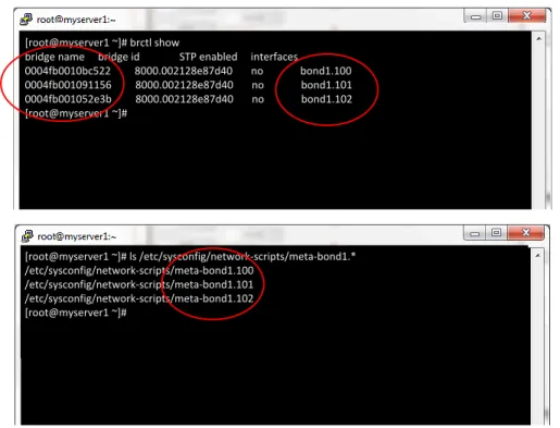
The third diagram in Figure 10 shows output from the brctl command. The brctl command displays the relationships between the Xen bridges and the logical network interface that “connects” the bridge to the rest of the world. There is a direct relationship between the network ID (2) and the name of each Xen bridge (3). The MAC address (4) is related to the bond or port that network traffic flows to and from the guests, while (5) shows which VLAN segment the Xen bridge is related.
The forth diagram shows the final piece of the puzzle, which is the relationship between the name of the VLAN segment (5) and the actual metafile (6) that will need to be copied.
[root@myserver1 ~]# brctl show
bridge name bridge id STP enabled interfaces 0004fb0010bc522 8000.002128e87d40 no bond1.100 0004fb001091156 8000.002128e87d40 no bond1.101 0004fb001052e3b 8000.002128e87d40 no bond1.102 [root@myserver1 ~]# [root@myserver1 ~]# ls /etc/sysconfig/network-scripts/meta-bond1.* /etc/sysconfig/network-scripts/meta-bond1.100 /etc/sysconfig/network-scripts/meta-bond1.101 /etc/sysconfig/network-scripts/meta-bond1.102 [root@myserver1 ~]#
Figure 10: Diagram showing the relationship between the network ID in the Oracle VM Manager and the Xen bridges on the Oracle VM Servers
1 2 3 4 6 5
Revealing Oracle VM network IDs
The network IDs are not shown by default in Oracle VM Manager, so they need to be revealed by selecting the View pull down menu from the toolbar and then choose ID from the menu. The only reason no real need during the integration process
Figure 11: Screen shot showing the default view for the Networking tab with the ID column hidden
Figure 12: Screen shot showing how to reveal the hidden ID column
Virtual NICs
Do not use the same range of virtual MAC addresses on the Site B Oracle VM Manager. The virtual MAC addresses from Site A will be imported along with the Oracle VM Guests when the Site A repository is imported into the Site B server pool.
Storage Considerations
The solutions presented in this paper are centered on replicating and using the storage repositories as well as any physicals disks presented to Oracle VM Guests containing applications and application data associated with each Oracle VM Guest. It is important that you understand what does and does not need to be replicated to the recovery site (Site B).
Pool file system
Each server pool has a single file system that contains metadata about the server pool itself. Pool file systems should not be replicated to the recovery site since at the end of the integration process the recovery site (Site B) should have a server pool ready to manage and run the Oracle VM Guests from the primary site (Site
A) during a failover. Pool file systems contain information that is specific to the particular Oracle VM Servers, storage arrays and other hardware at the primary site – the servers and storage at the recovery site will be completely different so copying the pool file system is unnecessary and will make the server pool at the recovery site unusable.
Physical disks
Only physical disks presented to the Oracle VM Guests should be replicated to the recovery site. Physical disks for applications and data are not part of the storage repositories, so provisions for replicating these separately must be made; this must also be part of your overall disaster recovery solution.
Ensure all physical disks containing the following types of data are replicated to the recovery site: Physical disks containing storage repositories for Oracle VM Guests, Oracle VM Templates,
assemblies, clones of guests that used by the server pool being replicated to the recovery site Physical disks containing applications being used by the pool being replicated to the recovery site Physical disks containing application data being used by the applications being replicated to the
recovery site
Storage repositories
Storage repositories are assumed in this document to be physical disks presented to Oracle VM Servers using one of the SAN protocols such as FCP or iSCSI. The storage repositories contain the
configuration files, system boot images and any associated virtual disks for each Oracle VM Guest. The storage repositories are replicated from the primary site (Site A) to the recovery site (Site B),
Stop!
It is very important each site maintain its own set of unique virtual MAC addresses.
!
Critical Concept!“imported” into the Site B Oracle VM Manager, and then presented to the Site B failover server pool where the Site A Oracle VM Guests will be managed.
It is important to note that the “import” process for all physical disks including storage repositories should only occur when a failover is “triggered”. The import process as described in this document is currently a manual process but can be automated using the Oracle VM CLI. Oracle suggests
contracting custom automation solutions through Oracle Advanced Customer Support Services or one of our excellent systems integrators from the Oracle Partner Network.
The storage repositories must be replicated from Site A to Site B on a periodic basis defined by the recovery point objective that is most acceptable for a given business computing environment. This decision should be made by the team responsible for the overall business continuity solution at your site.
Virtual disks
Virtual disks such as the system.img system disk for each Oracle VM Guest are simply files that reside in each storage repository. Virtual files are replicated by default when the storage repositories are replicated to the recovery site.
Data Replication Software
The actual replication of storage containing applications, application data and Oracle VM repositories between sites is completely outside the purview of Oracle VM 3 or this technical white paper. Your storage vendor should have data replication products as well as technical white paper and user guides that explain how to develop and implement data replication between sites for disaster recovery. The data replication solution you develop is the most critical piece of the overall a disaster recovery solution and the backbone of the process explained in this document.
Oracle VM is storage vendor neutral, but it is extremely critical that the replication technology incorporated into your overall business continuity solution copy 100% of each physical disk (LUN) block-for-block to ensure the metadata containing the WWID of each disk is exactly the same at both sites. This is critical since the physical disks containing applications and application data are presented to the Oracle VM Guests using a unique UUID and the guest operating systems will not be able to see the physical disks if the WWID is not the same on Site B as they were on Site A.
Each disk (LUN) has two numbers associated with it: a UUID and WWID. Oracle VM creates devices special files using the WWID (worldwide ID); the device special file names can be seen in the Oracle VM Manager whenever you select and expand the view for a physical disk under the Storage tab. The device names are usually something like /dev/mapper/360a9800056724433565a6d56304b336b as the screen shot illustrates in Figure 14 below.
!
Critical Concept!It is extremely important that the software used to replicate the physical disks across data centers copy 100% of the disk metadata block-for-block to ensure the WWID for each disk is exactly the same for both sites (VPD page83).
Figure 14: Showing the WWID and corresponding device special file for a physical disk
Unlike the UUID for a disk, the WWID is exactly the same on any server it is presented – even if the disk is presented to different servers as a block device in two different data centers in different parts of the world; the WWID never changes. This makes it very easy to identify the same disk presented to multiple servers. This is why it is so important that the WWID be copied along with the replicated disk.
Simple names for physical disks
The simple names (user friendly names) for physical disks are maintained in the Oracle VM database. Since the database is not being replicated between sites, the simple names are not persistent. These can be manually updated as needed or the Oracle VM Command Line Interface (CLI) can be used to automate scanning for simple names in the daily XML dump file and then adding the names to the Oracle VM database at the recovery site.
Triggering a DR Failover
Triggering a disaster recovery failover using Oracle VM should be a manual process. This ensures the operations team has verified that a failure of the primary site has actually occurred. The manual process for triggering and performing a site failover is articulated in Part 3 of this document.
Develop Meaningful Conventions
Please note that the object names, simple names (user friendly names), locations, configuration examples and screen shots shown in this document are simply used to convey concepts and are not meant to be taken literally. Use IP addresses and naming conventions that are appropriate for your environment.
Oracle VM Version Considerations
This document is written specifically for Oracle VM 3.1.1. Please do not use the document with earlier or later versions of Oracle VM.
Product Licensing
Please check with your account representative or Oracle product licensing before making decisions about licensing products for multisite disaster recovery solutions.
Conclusion
At this point you should have a very good grasp of the concepts surrounding the integration process needed to incorporate Oracle VM into a new or existing business continuity architecture. One of the primary concepts is all Oracle VM Managers at various sites should be completely independent of each other. It is also very important that the network name space be exactly the same for Oracle VM virtual machine networks, including the Oracle VM network ID associated with each virtual machine network. Part 2 of this document explains how to prepare and install Oracle VM Manager at the recovery site. It is assumed by this paper that the Site B Oracle VM Manager has not, and will not be installed until the primary site is completely validated and stable.
Part 3 of this document explains how to perform a site failover. The site failover should be performed once the integration process has been completed in order to validate the viability of the solution as well as familiarize the operations staff with the process. As with any good disaster recovery solution, periodic site failovers should be scheduled to ensure the process still works over time.
Part 2: Integrating Oracle VM into a DR Environment
Process Overview
Oracle VM is simply a small piece of an overall business continuity solution. Part 2 of this document explains the steps needed to prepare, install and integrate Oracle VM into your multisite disaster recovery solution. All other aspects of a disaster recovery solution are assumed to be in place before integrating Oracle VM into the overall solution.
The diagram shown in Figure 15 provides a brief look at all the steps involved with integrating Oracle VM into a multisite disaster recovery solution.
Figure 15: Process flow for integrating Oracle VM into a disaster recovery plan
Note that all of the steps in Figure 15 are accompanied by colored text used to denote the level of detail provided in this document. The key to the meaning of the text is as follows:
Normal Oracle VM process: A step with this designation means there is nothing special about that particular step beyond the normal Oracle VM implementation process; you should already be very familiar with the process noted in a step with this designation.
DR specific Oracle VM process: A step with this designation means that the integration process deviates in some way from the normal implementation methodology for Oracle VM. You should pay particular attention to any step with this designation since it will impact the success of your project.
Follow vendor specific solution: A step with this designation indicates that the step has a vendor specific solution and process. This paper articulates what Oracle VM will expect for these steps, but offers no particular way of accomplishing the task since that should have been devised by the team responsible for devising the overall DR solution at your site.
Before Beginning the Installation and Configuration Process
The following subsections discuss some important things to remember before beginning the process of installing and configuring Oracle VM at Site A and B.
Servers for Site B
All Oracle VM Servers should already be cabled and powered up at Site B. Network cabling should be verified to ensure each network device is connected to the correct subnets, VLANs or broadcast domains on the Ethernet switches. Service processors such ILOMs should be configured and tested for access before attempting to undertake any tasks related to Part 2 of this white paper.
The Oracle VM Server product should be installed on each server, but the servers must not be part of any existing server pools. The servers must not belong to an existing server pool since it will
prevent you from matching the Site A network IDs for the virtual machine networks at Site B. If you are using bonded ports without VLANs, then the Oracle VM Servers must not be part of any existing server pools. However, if you plan on using VLANs for 100% of the virtual machine networks at Site B, then the servers can already be part of an existing server pool.
Storage for Site B
All storage arrays for Site B should be up and running before installing and configuring Oracle VM. All storage that will be used to create the recovery server pool such as pool file system and a temporary storage repository should already exist and be presented to the Oracle VM Servers at Site B.
The pool file system and a temporary storage repository (discussed below) should already exist and be presented to the Oracle VM Servers. Fibre Channel disks will appear as soon as Oracle VM Server is installed if your Fibre Channel HBAs are configured correctly and the LUNs are presented to each of the severs; this will make it easier to validate that the physical disks can be seen by each of the servers. Physical disks presented via iSCSI will not appear until the iSCSI array is registered in the Oracle VM Manager. So, physical disks presented to Oracle VM Servers via iSCSI cannot be verified until much
Stop!
The Site B Oracle VM Servers must not belong to an already existing server pool if you are only using bonded interfaces without VLANs. You will not be able to match the network IDs from Site A if the servers already belong to a server.
later in the process. However, ensure that the physical disks are presented to the Oracle VM Servers before beginning the install and configuration of Site B even though the disks won’t be seen by the server until later on.
Pool file system
As mentioned in Part 1, a pool file system that is completely independent of the pool file system at the primary site (Site A) must be presented to the Oracle VM Servers at the recovery site (Site B).
Storage repository
A small, temporary storage repository should be created and presented to all Site B Oracle VM Servers. This temporary repository will be used to store a few very simple Oracle VM Guests that will be used exclusively for validating network and storage access at Site B. A 36 Gigabyte storage repository is all that is needed. Just enough space to contain an Oracle VM Template for Oracle Linux and one or two Oracle VM Guests that will be created using the templates.
Oracle VM Guests for validation
Create one or two Oracle VM Guests based on an Oracle VM Template once the Site B server pool is created and the temporary storage repository is presented to all the Site B Oracle VM Servers. The Oracle VM Guests will only be used to validate networking to ensure everything is configured correctly at Site B. Do not add any applications or do anything with the guest operating systems other than configure networking.
The goal is to keep the guest operating systems very simple with just enough changes to emulate the network configuration for Site A Oracle VM Guests. We do not want to introduce too many changes to the operating systems that cause more troubleshooting than necessary. These temporary Oracle VM Guests can be removed from the server pool once the Site B networking has been validated.
Step 1: Install and Configure Oracle VM at Site A
Ensure that Oracle VM has been installed, fully configured to fit the requirements of your computing environment. Also ensure the entire Site A solution has been validated and is completely stable before and during the entire Oracle VM integration process. Installing and configuring Oracle VM 3 is beyond the scope of this document. Please refer to the Oracle VM Documentation on Oracle Technology Network for release 3.1.1 for detailed information regarding the installation and configuration of server pools and Oracle VM Guests.Step 2: Install Oracle VM Servers at Site B
Note that this step does not include installing the Site B Oracle VM Manager – it is important that you do not install the Oracle VM Manager until later steps.
Stop!
It is especially important that Site A remain completely stable before and during the entire integration process. There should be zero changes being made at the Site A environment.
Step 2.1: Install Oracle VM Server on Site B servers
Install the Oracle VM Server product on the physical servers at Site B. Once this is completed, we will make some manual modifications to the installed operating system before the servers are discovered. The manual modifications are explained in step 3.
Step 3: Replicate Site A Network IDs to Site B
This step is very import and must be completed before discovering the Site B Oracle VM Servers with the Site B Oracle VM Manager. Please refer to the Network Considerations section in Part 1 of this paper if you are not familiar with the purpose of this step or are not familiar with the reason for ensuring virtual machine network IDs match at both sites.Step 3.1: Determine which metafiles to copy
The network bridge names used for the virtual machine networks on
the site B servers must match the bridge names on site A servers. This is a very important step to ensure the Oracle VM guests don’t require manual editing to straighten out false networks during an actual failover attempt.
The reason behind this particular step and the method for determining which network metafiles must be copied is explained in Part 1 of this paper. Please review the section on network considerations in Part 1 of this document if this step seems confusing or unclear.
The following is an example of the process for copying the metafiles – it is only an example – copy only the actual metafiles that are appropriate for your environment. In the case of this example, only three network metafiles will need to be copied assuming the three fictional VLANs shown in Figure 16 below.
Figure 16: From Site A, copy only the metadata files for Oracle VM networks with the Virtual Machine channel assigned
Run the following commands shown in Figure 17 below on any Site A Oracle VM Sever that is part of the disaster recovery solution.
Stop!
Don’t attempt to install Oracle VM Manager or discover servers at Site B until step 3 is completed! Your Site A Oracle VM Guests will not be able to use the networking at Site B if this step is skipped.
[root@myserver1 ~]# brctl show
bridge name bridge id STP enabled interfaces 0004fb0010bc522 8000.002128e87d40 no bond1.100 0004fb001091156 8000.002128e87d40 no bond1.101 0004fb001052e3b 8000.002128e87d40 no bond1.102 [root@myserver1 ~]# [root@myserver1 ~]# ls /etc/sysconfig/network-scripts/meta-bond1.* /etc/sysconfig/network-scripts/meta-bond1.100 /etc/sysconfig/network-scripts/meta-bond1.101 /etc/sysconfig/network-scripts/meta-bond1.102 [root@myserver1 ~]#
Figure 17: Use the above commands to determine which files to copy (fictional example – yours will be different)
Step 3.1: Copy the metafiles to Site B Oracle VM Servers
Armed with the names of the network metafiles from the previous step, log into each Site B Oracle VM Server and run the commands shown below in Figure 18:
[root@myserver3 ~]# cd /etc/sysconfig/network-scripts
[root@myserver3 ~]# scp myserver1:/etc/sysconfig/network-scripts/meta-bond1.100 . [root@myserver3 ~]# scp myserver1:/etc/sysconfig/network-scripts/meta-bond1.101 . [root@myserver3 ~]# scp myserver1:/etc/sysconfig/network-scripts/meta-bond1.102 . [root@myserver3 ~]# exit
Figure 18: Use the above commands to copy the metafiles from Site A to Site B (fictional example – your file names will be quite different)
Move on to the next step once you have copied the network metadata files to all servers that are part of the Site B solution.
Step 4: Install Oracle VM Manager at Site B
This document assumes that Site A is fully configured, running Oracle VM Guests and every aspect of the environment stable and validated before installing and configuring the Site B computing environment. It is extremely important that the Site A be stable: there should be absolutely zero changes being made to the Site A environment before and during the integration process.Stop!
Pay close attention to step 4! This is the key to allowing Site A storage repositories to be used by the Oracle VM Manager at Site B. It is especially important that Site A remain
Step 4.1: Get the UUID of the Site A Oracle VM Manager
This important step ensures the storage repositories from Site A and be used by the Site B Oracle VM Manager during a failover with only very minor manual intervention. This is the most critical step during the implementation of Site B Oracle VM Manager and server pools. To install Site B Oracle VM Manager with the same UUID as the Site A Oracle VM Manager you will need to get the UUID from the Site A Oracle VM Manager as shown in Figure 19 below. Just select the About menu from the top of the Oracle VM Manager interface…
Figure 19: Select About from the Help menu on the Site A Oracle VM Manager
Then highlight and copy the UUID into your desktop copy/paste buffer. You can paste the UUID onto the command line of the management server or VM guest where you will be installing the Site B Oracle VM Manager (note the Oracle VM version shown below is an example only).
Figure 20: Copy the UUID for the Site A Oracle VM Manager into the copy/paste buffer of your desktop
Now log into the server or VM guest where you are going to install the Site B Oracle VM Manager. Obviously, the management server or VM guest should be located somewhere at Site B. You should have copied the same Oracle VM Manager installer ISO image you used for install Site A and mounted it as a loopback device under the /mnt mount point. Choose the production install just like you did for the Site A Oracle VM Manager - pointing to a different
database than you used for Site A of course. Run the following command once you have logged into the management server at Site B:
[root@mymanagerB~]# mount –o ro,loop /tmp/<manager ISO> /mnt
[root@mymanagerB~]# cd /mnt
[root@mymanagerB~]#./createOracle.sh
[root@mymanagerB~]#./runInstaller.sh --uuid <the UUID you copied from above step>
Move on to the next step after the Oracle VM Manager installer has completed the install.
Step 5: Discover Oracle VM Servers at Site B
Follow the normal method for discovering servers using the Site B Oracle VM Manager. There is nothing different or special about the process for Site B. Figure 21 shows an example of Site B with the newly discovered servers.
Figure 21: All of your Oracle VM Servers should appear under the Unassigned Servers folder after discovery
Step 6: Configure network interfaces for Site B
Step 6.1: Ensure all Ethernet interfaces are available
Configure the network interfaces on all the Site B Oracle VM servers. Just like a normal implementation of Oracle VM, one of the first tasks that should be accomplished after discovering all the Oracle VM Servers is to configure all network interfaces. The only interface that is configured on all Oracle VM Servers after an initial discovery is bond0.
Remember…
The physical and logical aspects of your Site B network can be quite different from the Site A network. You can have more or less physical network interfaces, different bonding, different VLANs, etc. Read step 2.5 carefully for more information.
Stop!
Make sure you choose the production install and point to a completely different database server than the one you used for the Site A Oracle VM Manager.
Step 6.2: Configure bonded interfaces
Next configure the bonded interfaces using the appropriate physical interfaces (ports) for the Site B server pool. The interfaces that are assigned don’t necessarily need to be the same as Site A. For example, Site A might use eth0 and eth1 for bond port (1), eth2 and eth3 for bond port (2), while Site B might use eth0 and eth2 for bond port (1), eth1 and eth3 for bond port (2). Just ensure the bonding is configured correctly for Site B.
Validate that all bonds are working as expected before proceeding any further – just use the same process for validating bonded interfaces that was used for Site A.
Step 6.3: Create VNICs for Site B
Ensure you create the same exact range of virtual MAC addresses for Site B as exist at Site A.
Step 7: Configure Oracle VM management networks
The initial server discovery will create the normal management network plus all the networks from Site A something like the example shown below. At this point you should configure the Oracle VM management networks as appropriate for Site B.
Figure 22: Newly discovered networks including the default management network and the networks copied from Site A
For example, if your solution includes creating a dedicated network for server management, heartbeat and live migration, then this should be accomplished before moving on to the next step. Perhaps you need to configure a dedicated network for storage; all of the management network should be in place before proceeding any further.
Figure 23 below illustrates an example of what the networks might look like after adjusting them. These are just examples to help explain the possibilities of how networking might be adjusted and should not be taken literally.
Figure 23: Example showing adjusted management networks with dedicated server management, heartbeat and migration networks
Step 8: Configure Oracle VM Guest networks
This step ensures all Oracle VM networks with the virtual machine network channel have the same exact network ID at both Site A and B. This is an extremely important step whether yourenvironment uses a global network name space or not – the network IDs for Oracle VM virtual machine traffic must be the same at both sites.
During the server discovery the information in the metafiles forces
Oracle VM Manager to create “orphaned” virtual machine networks with names that match the corresponding Site A network names as shown in Figure 24 below. At this point the orphaned networks only exist in the user interface and no actual Xen bridges have been created yet on the Oracle VM Servers. The next two steps force Oracle VM to create the corresponding Xen bridges and network interface relationships on the Oracle VM Servers.
Figure 24: Newly discovered networks created from the metafiles copied from Site A
Stop!
This step must not be skipped or you will have to manually edit the network configuration for each and every Oracle VM Guest before you can start them at Site B.
Step 8.1: Remove the virtual machine channel from each network
Edit each virtual machine network, changing nothing except the un-checking the virtual machine channel in the first dialog of the Edit Network wizard. This should result in all the virtual machine channels being temporarily removed from each network as shown in Figure 25 below. Removing the virtual machine channel from the newly discovered networks sets the stage to force the completion of the virtual machine networks on the Oracle VM Servers themselves.
Figure 25: Showing the virtual machine channel correctly removed temporarily – add the channels back in the next step
Step 8.2: Add the virtual machine channel to each network
Now simply add the virtual machine channel back to each network where it was removed. This entire process is a bit tedious, but forces the agent to actually create the appropriate Xen bridges with network IDs that match those found on Site A. The networks should look just like they did in the Oracle VM Manager interface before we started as shown in Figure 26. However, the difference which is apparent is that the Xen bridges and the relationships to the VLAN segments or bonds has been created on the Oracle VM Servers. These should now be fully functioning networks.
Step 8.3: Finish adjusting any other networks
Add any additional networks that are unique to Site B and ensure any other adjustments like adding simple names to networks are made.
Step 9: Register Storage at Site B
Register the Site B storage arrays. There is nothing special or different about this process from standard Oracle VM procedures; it is the same process that was used to register the storage arrays at Site A.
Ensure all Site B Oracle VM Servers that are part of the standby server pool are assigned the role of Admin Server. This is very
important since the replicated disks from Site A will only be discovered on Oracle VM Servers assigned the Admin role.
This should be completed whether you are using Fibre Channel or iSCSI for the storage protocol. Switch to the Storage tab then select the Unmanaged Fibre Channel Storage Array (or Unmanaged iSCSI Array). Select the Add/Remove Admin Servers wizard from the icon or context menu as shown in Figure 27.
Figure 27: Select Add/Remove Admin Servers wizard
Ensure that all Oracle VM Servers from the standby pool have been moved from the left hand box to the right hand box in the wizard as shown in Figure 28 below.
Stop!
All Oracle VM Servers in the sandby pool must be assigned as Admin Servers..
Figure 28: Ensure all Oracle VM servers in the standby pool are selected
Step 10: Create Server Pool at Site B
Create the Site B server pool using the Site B pool file system and the temporary storage repository discussed in the overview. There is nothing special or different about this process from standard Oracle VM procedures; it is the same process that was used to create the server pool at Site A.
Step 11: Validate Server Pool at Site B
Create one or two Oracle VM Guests based on an Oracle VM Template once the Site B server pool is created and the temporary storage repository is presented to all the Site B Oracle VM Servers. The Oracle VM Guests will only be used to validate networking to ensure everything is configured correctly at Site B. Do not add any applications or do anything with the guest operating systems other than configure networking.
The goal is to keep the guest operating systems very simple with just enough changes to emulate the network configuration for Site A Oracle VM Guests. Do not introduce unnecessary changes or modifications to the operating systems since that will increase the likelihood of technical complications resulting in more time consuming troubleshooting than necessary. These temporary Oracle VM Guests can be removed from the server pool once the Site B networking has been validated.
Step 12: Implement Storage Replication between Sites
Once both Site A and Site Oracle VM Managers are fully configured. Implement the multisite storage replication recommended by your storage vendor. The goal is to ensure the physical disks from Site A containing the storage repositories, applications and application data are being replicated to Site B on a regular, periodic basis that conforms to the design goals architected by the operations team at your organization.
Conclusion
The integration of Oracle VM should be in place at this point. The next major task is to perform a site fail over to ensure the entire solution works as expected.
Part 3: Executing a Failover from Site A to Site B
The Process Flow
The following diagram describes process flow briefly describes all the steps needed to initiate a failover to validate the entire solution works correctly. The following steps assume site-to-site synchronous or asynchronous storage replication is in place and working as expected.
Some of the steps are explained in detail (In scope) while other steps are discussed without much detail since some steps involve accomplishing tasks using other pieces of your overall disaster recovery solution (Not in scope). An example would include Step 2 below which depends entirely you accomplishing the task using the data replication software from your storage; data replication is completely outside of Oracle VM control.
Figure 29: Process flow for accomplishing a failover from site A to site B
Note that all of the steps in Figure 29 are accompanied by colored text used to denote the level of detail provided in this document. The key to the meaning of the text is as follows:
Normal Oracle VM process: A step with this designation means there is nothing special about that particular step beyond the normal Oracle VM implementation process; you should already be very familiar with the process noted in a step with this designation
DR specific Oracle VM process: A step with this designation means that the integration process
deviates in some way from the normal implementation methodology for Oracle VM. You should pay particular attention to any step with this designation since it will impact the success of your project
Follow vendor specific solution: A step with this designation indicates that the step has a vendor specific solution and process. This paper articulates what Oracle VM will expect for these steps, but offers no particular way of accomplishing the task since that should have been devised by the team responsible for devising the overall DR solution at your site.
Step 1: Prepare Site A for failover
Simply ensure all Oracle VM guests are halted at Site A before beginning the failover process.
Figure 30: Site A showing all Oracle VM Guests have been stopped
Step 2: Present replicated storage to Oracle VM Servers
This step is completely dependent on your storage vendor and the method used by the vendor to present or map will vary depending on the storage array. The end result should be that the replicated Site A storage repository and any other physical disks containing applications and application data for each Oracle VM Guest should be presented to all Site B Oracle VM Servers.
Step 3: Discover replicated storage on Oracle VM Servers
This step will re-probe the SCSI bus on each Oracle VM Server and find all the replicated physical disks from Site A. The Site A storage repository and any physical disks the Oracle VM Guests depend on will be imported at this point.
Step 3.1: Rescan for disks on Oracle VM Servers
Log into the Site B Oracle VM Manager and display the Storage tab. There should be no Site A disks found in the Site B Oracle VM Manager before a site failover has been executed as shown in Figure 31 below. Only the pool file system for the recovery site server pool should be found at this point.
Figure 31: There should be no Site A disks found in the Site B Oracle VM Manager before a site failover has been executed – only the pool file system for the recovery site server pool
Ensure Admin Servers have been assigned to the Unmanaged Fibre Channel Storage Array as shown in Figure 36 and Figure 33 below. Newly presented Fibre Channel physical disks will only be discovered on servers that are designated as Admin servers so make sure all server in the pool are
selected. The requirement for Unmanaged iSCSI Storage Array is slightly different: not all the servers need to be designated as Admin Servers when using iSCSI as the storage protocol. You should select all servers in the pool as a best practice for iSCSI, but it is not a requirement.
Figure 32: Open the Add/remove Admin Servers wizard
The dialog for Add/Remove Admin Servers should show all servers in the pool as illustrated below. Move any servers belonging to the Site B server pool from the left box to the right box if any remain on the left.
Figure 33: Ensure all servers in the pool are selected for Fibre Channel or iSCSI
Refresh the Unmanaged Fibre ChannelStorage Array (shown in Figure 34) or the Unmanaged iSCSI Storage Array – the choice will depend on which storage protocol used in your environment.
Figure 34: Refresh the appropriate storage array (Unmanaged Fibre or iSCSI)
Figure 35 below should show that all replicated Site A physical disks now appear in the Storage tab of the Site B Oracle VM Manager after running rescan_for_disks on the Oracle VM Servers. As
mentioned earlier, the simple names for the disks are not persistent between sites. However, the simple names are not needed by the guests since the Oracle VM Guests rely on the device special file names such as /dev/mapper/360a9800056724433565a6c56304b336b. This is why it is so important that the WWID for each replicated disk is the exactly the same on both Site A and Site B Oracle VM Servers.
Figure 35: All replicated disks should be added to the Site B Oracle VM Manager automatically after rescan_for_disks
Step 3.2: Add the Site A repository to the Site B OCFS2 cluster
The storage repository is formatted with OCFS2 and is “owned” by the OCFS2 cluster at Site A. The ownership of the disk must be changed from the Site A to Site B OCFS2 cluster. The process is exceedingly simple and only requires the fsck.ocfs2 be run against the disk containing the storage repository. The fsck.ocfs2 command will automatically change the OCFS2 cluster name to match the cluster on the server where the command is being executed.
All we need is the device special file name for the disk containing the storage repository. Open the disk details related to the disk containing the Site A repository, highlight and copy the device special file (Path) using your mouse as shown in Figure 36 highlighted in the red circle.