Ulm University| 89069 Ulm | Germany Faculty for Engineering and Computer Science Institute for Databases and Information Systems
Enabling Personalized Business
Process Modeling:
The Clavii BPM Platform
Master Thesis at Ulm University
Submitted by: Klaus Kammerer
Klaus.Kammerer@uni-ulm.de
Reviewer:
Prof. Dr. Manfred Reichert Prof. Dr. Peter Dadam
Supervisor: Dipl.-Inf. Jens Kolb
ACKNOWLEDGEMENTS:
First and foremost I offer my gratitude to my supervisor, Jens Kolb, who has supported me throughout my studies with his enthusiasm and knowledge.
I would like to thank Prof. Dr. Manfred Reichert for making this thesis possible.
Many thanks to my fellow students and Clavii workmates Kevin Andrews, Stefan Büringer, and Britta Meyer.
I would particularly like to thank my family, who made my studies possible and encouraged all my decisions.
Finally, I thank Vanessa Schmitt. She was always cheering me up and stood by me through the good times and bad.
c
2014 Klaus Kammerer
Typeset: PDF-LATEX 2ε Print: Ulm University
Abstract
Increasing adoption of business process management systems has resulted in large busi-ness process models comprising hundreds of activities. Particularly, such process models are hard to understand and maintain. This issue requires innovative approaches to simplify and personalize process models. Therefore, this thesis introduces fundamentals for pro-cess views offering personalized perspectives for propro-cess participants by abstracting not necessary information. Furthermore, an approach for a domain-specific process modeling language, so-called Process Query Language, is presented. The latter offers process modeling notation independent abilities to define, search, and modify process models as well as process views. The proof-of-concept implementation, so-called Clavii BPM platform, shows up as integrated solution for simple, web-based business process modeling and execution. Thus, it implements basic concepts for process views and the PQL language.
Contents
1 Introduction 1
2 Fundamentals on Business Process Management 3
2.1 Business Process Management . . . 4
2.1.1 BPM Lifecycle . . . 4
2.2 Business Process Modeling . . . 5
2.2.1 Process Model . . . 6
2.2.2 Process Modeling Notation . . . 6
2.2.3 Block-Structured Process Models . . . 10
2.2.4 Workflow Patterns and Change Patterns . . . 11
2.3 Executing Process Models . . . 12
2.4 Process-Aware Information Systems . . . 13
2.5 Summary . . . 14
3 Overview on Abstracting Process Models by Applying Process Views 15 3.1 Fundamentals on Process Views . . . 17
3.1.1 Process View . . . 17
3.1.2 Control Flow View Creation Operations . . . 19
3.1.3 Control Flow View Update Operations . . . 21
3.1.4 Migration of Process View Change Sets . . . 24
3.1.5 Process View Refactoring Operations . . . 26
3.2 Discussion . . . 28
3.3 Requirements for a BPM-Specific Language . . . 29
4 Process Query and Modification Language 33
4.1 PQL Process Meta-Model . . . 34
4.1.1 Process Model Correctness and Expressiveness . . . 37
4.1.2 PQL Process Model Mapping . . . 38
4.2 Process Query Language . . . 39
4.2.1 Process Model Discovery Representation . . . 39
4.2.2 PQL Process Model Change Operations . . . 43
4.2.3 PQL Process Views . . . 45
4.2.4 PQL Modularity Concept . . . 48
4.3 Software Architecture Supporting PQL . . . 49
4.3.1 PQL Request . . . 50 4.3.2 Architectural Components . . . 52 4.3.3 Processing Pipeline . . . 54 4.4 Summary . . . 56 5 Activiti BPM Platform 57 5.1 Activiti Toolstack . . . 58
5.2 Process Modeling Support . . . 59
5.2.1 Java Object Representation for Process Models . . . 59
5.2.2 XML Representation for Process Models . . . 60
5.2.3 Custom Extensions of Process Models . . . 62
5.2.4 Expression Language . . . 62
5.3 Activiti Server Component and Java API . . . 63
5.4 Summary . . . 64
6 The Clavii BPM Platform 65 6.1 Principles . . . 66
6.2 Proof-of-Concept Implementation Architecture . . . 67
6.3 Functionalities . . . 69
6.4 Managing Process Models . . . 73
6.4.1 Process Model Representation . . . 74
6.4.2 Block-Structural Constraints . . . 76
6.4.3 Process Model Graph Utilities . . . 78
6.4.4 Process Model Creation . . . 79
Contents
6.4.6 Process Model Update Procedure . . . 82
6.5 PQL Proof-of-Concept Implementation . . . 84
6.5.1 Generating a Parser for Domain Specific Languages . . . 87
6.5.2 PQL Request Representation . . . 89
6.5.3 Parsing and Conversion Procedure . . . 91
6.6 Process View Implementation . . . 92
6.6.1 Creating a Process View . . . 92
6.6.2 Updates on Process Views . . . 95
6.7 Summary . . . 97
7 Related Work 99 8 Conclusion 105 A Appendix 107 A.1 Activiti Code Examples . . . 107
1
Introduction
In times of the information age companies are more than ever confronted with big challenges [19]. On the one hand side customers ask for even lower prices, faster product delivery and higher support—on the other side companies aim at maximizing their return on invest. One solution may be to manage and optimize efficiency through managing internal process flows.
Companies often attach significant importance toBusiness Process Management (BPM)
[26], but comprehensive BPM software platforms are costly and require profound BPM knowledge. Additionally, business processes are subject of continuous change demanding for advanced technologies supporting a fast adaption and optimization of company wide business processes. BPM software platforms have to address these challenges.
Large companies are able to use a great variety of BPM platforms, which includeBusiness Intelligence1, Service-Oriented Architectures orBusiness Rules. Small and medium-sized companies are often overcharged with an integrated BPM platform, since BPM knowledge— or available platforms are too complex and expensive for them [34]. BPM platforms are often developed for comprehensive mapping of ideally all accruing internal and external work-flows. They follow a top-down approach, which requires a high-level view on a companies processes.
This thesis presents theClavii BPM platform (Clavii for short), an integrated, web-based
solution to manage, execute, and optimize process models. It illustrates different concepts to simplify process models. Clavii is optimized for small and mid-sized companies with limited experiences with BPM. Therefore, Clavii offers a simple and self-explaining user interface (UI) trying to close the gap between organizational and technical BPM aspects. Assisted process modeling bypasses technical difficulties to ensure, for example, correct control and
data flow in process models. Advanced concepts, e.g., process viewsfor process model
abstractions, streamline the management of large and complex business processes. As
a research result for this topic the Process Query Language (PQL)is presented. PQL is
a domain-specific language for process modeling and enables the definition of notation-independent change and abstraction operations. Moreover, Clavii features a simplified data flow by supporting business objects and allows for an easy automation of BPM tasks. Hence, end-users are not required to develop software component tasks, like premised for other BPM platforms. Therefore, execution-ready generic tasks for process automation can be obtained in a store and require little or no configuration effort. Furthermore, process models for common activities, like delivery processing, can also be obtained in the store to further minimize initial obstacles.
Section 2 introduces fundamentals on business process management. Section 3 presents theoretical approaches for process views. Section 4 introduces PQL as well as a generic software architecture supporting PQL. Section 5 presents the Activiti BPM platform as base of the developed Clavii BPM platform. Section 6 introduces the Clavii BPM platform by describing various innovative principles and its software architecture. Section 7 discusses related work. A conclusion is given in Section 8.
2
Fundamentals on Business Process
Management
In the following fundamentals of Business Process Management, serving basic knowledge for further aspects of this thesis, are introduced [29, 70, 82]. Section 2.1 explains Business Process Management and the BPM lifecycle in general. Section 2.2 describes essentials, like the definition of a process model, its graphical description model and an introduction to BPMN 2.0, a de-facto standard for todays process modeling notations. Executing business processes is explained in Section 2.3.
2.1 Business Process Management
The European Association of BPM (EABPM) definesbusiness process management as
following: "Business Process Management or BPM is synonymously used for process
man-agement. A process is a set of defined operations (i.e., activities, tasks), that are executed by human or a system to achieve a goal. [...] Business process management is a system-atical approach to capture, execute, document, measure, monitor and control automated and non-automated processes to reach goals defined by a business strategy. BPM com-prises an emerging IT-supported determination, enhancement, innovation and preservation of end-to-end processes" [39].
In practice a company introduces business process management to document implicit business processes, automate certain tasks, and optimize internal workflows. Difficulties for a BPM introduction are the chosen degree of granularity, integration into existing workflows and a lack of BPM, and IT knowledge through a company [29].
The continuous process which accompanies with BPM is called BPM lifecycle.
2.1.1 BPM Lifecycle
The BPM lifecyle consists of the stepsdesign,modeling,execution, monitoringand
opti-mizationof business processes [6]. The BPM lifecycle is a never ending looping process. The time to complete each lifecycle step is not completely delimitable. In the following each step is described shortly.
Design: In this step tasks of a business process are identified on a high-level basis, organi-zational changes are discussed, and additional process dimensions (process participants, notifications, escalations) are defined.
Modeling: The modeling step creates a full documentation of a business process (i.e., by an explicit process model). It is also a validation step, where a specification is formalized (e.g., by utilizing BPMN). In this context even more details, like data handling have to be considered. Formalized process models are validated by simulating certain scenarios (cf. Section 2.2).
2.2 Business Process Modeling Execution: The process model is deployed in a PAIS (cf. Section 2.4). Afterwards, technical details are added in order to achieve the ability to execute the process model. Implementa-tions can be performed with a process notation like BPMN 2.0 and programming languages to develop automatically executed tasks (i.e., script and service tasks) within a process model (cf. Section 2.3).
Monitoring: At this time the implemented and executed process model is monitored against
defined business goals. Therefore, often so-calledkey performance indicators(KPIs) are
defined to gain convincing facts about efficiency.
OptimizationEvery preceding step, especially through experiences made by executions, creates suggestions or optimizations, that can be applied to a process model in order to increase its performance. Additional new aspects can show up, which are not covered before. As new requirements are carved out, the BPM lifecycle re-enters the design phase.
2.2 Business Process Modeling
Abusiness process describes the rationale of how an organization creates, delivers, and
captures value [62]. Aprocess model documents a business process and describes which
taskshave to be done to create a product or service. To build a process model thus it is necessary to be aware of what should be achieved and which participants are involved. Freund et al. constitute four questions to create a process model [29]:
• Which information is necessary?
• Which detail of information should be chosen?
• How can required information be acquired?
• Which modeling methodology should be used?
To decide which information is necessary a business process can be seen at different
point of perspectives. From anorganizationalperspective collaborations betweenprocess
participantsof a business process are considered, while afunctionalperspective focuses on which tasks have to be done and in what way these tasks can be organized (e.g. dividing
tasks into subtasks). Thebehavioralperspective defines the order in which these tasks
have to be executed to achieve the goal of a business process. Finally, theinformational
perspective describes resources and their production and consumption during the execution of tasks, as well as the informational flow between these tasks. Especially, the question which degree of detail should be chosen, is difficult to answer. Plenty of research exist, trying to give assistance to solve this question [13, 20, 29].
Process models are one possibility to simplify the process of formalizing certain structured tasks. Today they even take care of technical aspects and, if a particular maturity level of detail is reached, process models simply can be transformed into executable business process instances (cf. Section 2.3).
2.2.1 Process Model
Aprocess model is represented by a set ofprocess nodesand thecontrol flow between them. It is a single directed graph, which describes a business process. Process nodes,
for example, representtasks, which have to be done, to comply with the process model.
The control flow itself concerns about in which temporal chronology these tasks have to be executed.
Further, a process model may include additionalprocess elements, likeprocess data
el-ements. Every process element has variousattributes describing its properties (e.g., its name).
2.2.2 Process Modeling Notation
To describe a process model anotationis necessary. While the term notation is broadly
defined, even a textual document explaining a certain procedure can be seen as process model notation. Therefore, restrictions and guidelines are necessary to define, what exactly has to be the extend of a process model. To achieve the ability for executing a defined process model as process instance, additional information is required.
2.2 Business Process Modeling
An example for a simple process model notation arepetri nets[64]. Particularly, process
nodes or tasks refer to transitions and edges—described as control flow—refer to places. Further, process model notations exist having different scopes, goals, and expressiveness.
Examples to be mentioned areADEPT2[68],Event Process Chains (EPC)[78] andUnified
Modeling Language (UML) Activity Diagrams [24]. Generally, the expressiveness of a notation may be determined by applying workflow patterns (cf. Section 2.2.4).
In the context of this thesis, we apply the BPMN 2.0 as business process notation, a de-facto standard for graphical process model notation. A central goal of BPMN 2.0 is to be easily understandable by all process participants (i.e., business analysts, technical developers, and end-users) [30]. Thus, BPMN 2.0 creates a standardized bridge for the gap between business process design and process implementation. Particularly, BPMN 2.0 is an unstructured, graph-oriented process modeling notation. It consists of three different specification sub-classes:
• Descriptive Conformance Sub-Class (DCS): high-level process modeling comprising a subset of all existing BPMN elements
• Analytic Conformance Sub-Class (ACS): detailed modeling, including exception han-dling and events
• Common Executable Conformance Sub-Class (CECS): all elements
The CECS uses the whole expressiveness of BPMN 2.0. Such BPMN 2.0 defined process models are fully deployable to a PAIS supporting BPMN 2.0 (cf. Section 2.3). CECS
consists of the following element types: Flow Objects,Data Objects,Connecting Objects,
Swimlanes, andArtifacts.
Figure 2.1 shows a BPMN 2.0 process model consisting of selected BPMN 2.0 process elements described in the following.
Flow Objects can be further categorized in tasks, gateways, or events. These elements describe the functional nodes of a process model.
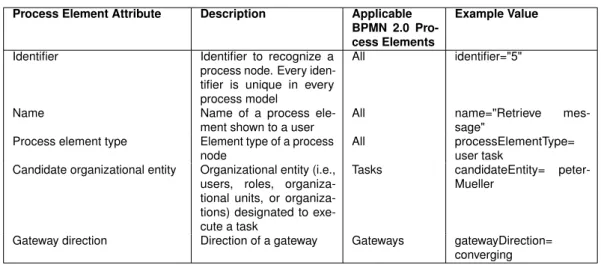
Tasksdescribe actions, a human or system should perform in a business process. Table 2.1 shows different types of tasks and their necessary technical attributes.
Sw iml an e Po ol Sw iml an e Start Event End Event
User Task Task
Script Task Exclusive Gateway Exclusive Gateway Parallel Gateway Parallel Gateway Conditional Sequence Flow Data Object Data Flow Sequence Flow Service Task TextAnnotation
Figure 2.1: BPMN 2.0 Process Model
Element Description Attributes
Task Generic task, which has to be executed by a process participant. This can be either a user or a system component.
id, name
User Task Auser task indicates, that a specified user has to interact with the business process. This can be achieved, for ex-ample, by providing a user form.
id, name, renderings, implementation, resources, ioSpecification, dataInputAs-sociations, dataOutputAssociations, loopCharacteristics, boundaryEven-tRefs
Script Task Script tasksare assigned to specified programming code, which can be auto-matically executed by a PAIS.
id, name, implementation, operationRef, ioSpecification, dataInputAssociations, dataOutputAssociations, loopCharacter-istics, boundaryEventRefs
Service Task Service tasks represent interfaces for interactions with other computer appli-cations and services.
id, name, implementation, operationRef, ioSpecification, dataInputAssociations, dataOutputAssociations, loopCharacter-istics, boundaryEventRefs
Table 2.1: BPMN 2.0 Task Types
Gateways describe points, where the control flow is split up by asplit gateway into two or
more branches or the latter is joined together by ajoin gateway. A gateway may express
either parallel control flows (i.e., all branches are considered), exclusive control flows (i.e., only one branch is selected for execution), or inclusive control flows (i.e., one or more branches are selected). Exclusive and inclusive gateways need defined decisions to determine the onward progress. Inclusive gateways are not used in this thesis, thus, they are not further discussed (cf. Table 2.2).
Eventsin BPMN 2.0 consist ofmessage,timer, anderror events(cf. Table 2.3).Message eventsindicate, that an external message is sent or received somewhere. Another business process or an intermediate message catch event is able to capture these messages taking
2.2 Business Process Modeling
Element Description Attributes
Parallel Gateway Aparallel gatewayindicates a control flow split up. Hence all branches are executed simultaneously.
id, name, gatewayDirection (only con-verging and dicon-verging)
Exclusive Gateway In contrast to parallel gateways an exclu-sive split gateway activates only one out-going branch. Each branch has a con-dition attribute splitting each activation into a disjunct activation set. Conditions can refer process data that is available during execution.
id, name, gatewayDirection (only con-verging and dicon-verging), default
Table 2.2: BPMN 2.0 Gateway Types
Element Description Attributes
Start Event Astart eventtriggers the start of a new process instance.
id, name
(also conditionalStartEvent, which has an additional
conditionalEventDefinition) End Event Anend event is the last element of a
process model. It indicates the end of a process path.
id, name
Table 2.3: BPMN 2.0 Event Types
further actions. An intermediate message catch event stops further execution of a process
instance, until an expected message has arrived. Timer events indicate a delay in the
process execution. This can be useful, when further steps of a business process, like sending a dunning letter in domain of accounting, first need a particular interruption.
BPMN 2.0 allows for data flows between tasks. Therefore, Data Objects may be used. A data flow is a process edge indicating a data flow between a Data Object and a certain task. [84] explains, that data flows are not frequently used during process modeling, thus, they are not further discussed in this thesis.
Connecting Objectslink above described flow objects to indicate a certain relationship or
interaction between them. Control flow objects describe the temporal aspects between
flow objects, whilemessage flow objectsanddata association objectsoutline a data flow.
Associations are used to link artifacts, like text annotations, to other flow objects in order to highlight their affinity.
Pools and Swimlanes are used to define process participants. Pools often represent or-ganizations. Swimlanes again subdivide pools to organize them in smaller units. To give
Element Description Attributes Sequence Flow Asequence flowconnects two nodes to
indicate a control flow.
id, name, sourceRef, targetRef, default Conditional Sequence
Flow Aconditional sequence flowis only acti-vated, when additional condition expres-sion returns true.
id, name, sourceRef, targetRef, condi-tionExpression
ConditionExpression, allowed only for sequence flow out of gateways, may be null
Table 2.4: BPMN 2.0 Connecting Objects
an example, a pool could represent anOrder Service. This pool can consists of twolanes,
Callcenter andDelivery Department.
Artifacts (i.e., Associations, Groups, TextAnnotations) show additional information to the user, which are not directly related to a sequence or message flow. They offer a possibility to document process models more precisely. Artifacts are not further discussed in this thesis, as Section 6 introduces concepts implementing them differently.
2.2.3 Block-Structured Process Models
Block structuresknown from programming languages are used to capsulate code fragments [51]. In particular, block structures must not overlap, but they can be nested arbitrary deeply. Figure 2.2a shows an example of a process model. The latter is not block-structured, as
SESE1does overlap withSESE2. In turn, Figure 2.2b is an example of a block-structured
process model.
Block SESE1 and block SESE2 in Figure 2.2b are so-called Single-Entry, Single-Exit
(SESE) blocks. A SESE defines a subgraph of a process model, where every process
node tupleA, Bconforms three characteristics:AdominatesB,Bpost-dominatesA, and
every cycle containingAalso containsBand vice versa [37]. In other words, process node
A dominates process nodeB in a process model, if every path from start to Aincludes
B. Further, process nodeApost-dominate process nodeB, if every path fromB to end
includesA. How to determine SESE blocks efficiently is described in [37].
A minimal SESE of a set of process nodesN is a tuple of two process nodes(n1, n2), where
n1denotes the entry of the SESE,n2the exit and describes the minimal SESE to surround
2.2 Business Process Modeling
be regarded (cf. Section 2.2.3). Figure 2.3 shows a process model with its different, nested
SESE blocks and a minimal SESE of three nodes(B, C, D).
A
D
B C
SESE 1
SESE 2
a) Process Model with Overlapping SESE Blocks
b) Block-structured Process Model
A
D
B C
SESE 1
SESE 2
Figure 2.2: Comparism of an Unstructured and Block-Structured Process Model
Block-structured process models are applied in the context of this thesis, because they are the basis for all presented process view operations.
2.2.4 Workflow Patterns and Change Patterns
Process model notations have different cardinality concerning their expressiveness. For
example, the BPEL process notation is not able to express anarbitrary cycle, while BPMN
2.0 supports them. Arbitrary cycles are cycles, that have more than one entry and exit point. Thus, BPEL is not able to express arbitrary cycles, because it is a block-structured process
notation. In [79] so-called workflow patterns are introduced, which describe a collection
of patterns describing common aspects of process modeling. The latter is divided into
different categories (e.g.,control flow patternsoradvanced branching and synchronization
A B G C D E F Process Model minimalSESE(B,C,D) SESE Block 1 SESE Block 2 SESE Block 3 / 4
with respect to block-structure: without respect to block-structure: minimalSESE(B,C,D) = (B,Y) minimalSESE(B,C,D) = (B,D)
X Y
Figure 2.3: SESE Blocks of a Process Model
In order to classify the cardinality of PAIS concerning their ability to change process models,
change patternsare introduced [81]. Change patterns describe and classify common control flow changes, like the insertion of a new task into a process model.
2.3 Executing Process Models
PAIS offer the ability to execute process models (cf. Section 2.4). Therefore, certain executable code (i.e., the logic of a task) can be attached to tasks, that, in turn, can be executed by a PAIS.
Particularly, BPMN 2.0 offers the ability to model and execute process models. Therefore,
several PAIS, like Activiti [67] or jBPM [17], allow for the direct execution of BPMN 2.0
defined process models.
Thereby, aprocess instancerepresents a concrete case in the operational business of a
company, for example, invoicing a service. From a technical point of view, it is a executable copy of a process model. It contains additional run-time information like an execution state
2.4 Process-Aware Information Systems
map of all present executable tasks and a log of already executed tasks. PAIS represent process instances highly memory optimized to handle hundreds or even thousands of process instances. Every business process instance has a business process instance lifecycle with different states [70].
2.4 Process-Aware Information Systems
AProcess-Aware Information System (PAIS) is a software application platform mapping business processes on a software basis offering the ability to support the BPM lifecycle. As illustrated in Section 2.2, there are different perspectives on business process management. A PAIS takes account of several perspectives, like operation, time, organization, behavior, information, and function, as well as offers different services to support them [70]. It also concerns about a separation of process logic and application code to be run by tasks in a process model.
Process Repository
Process Engine
State Machine Execution Component Manager User Interface
Process Editor Monitoring
Execution Component Editor
Worklist Manager
Configuration Editor
API Modeling Service Services
[….]
Build-time component Run-time component
A PAIS consists of several components [48]. These are separated logically intobuild-time
andrun-time services(cf. Figure 2.4). At build-time of a process model, a PAIS provides a process editor, with which a user is able to define and configure a process model by
using a graphical user interface. Resulting process models can then be stored in aprocess
repository, as well as its application service components. An execution component is a type of software to either execute certain programming code or provide interfaces to other software applications and services to map business logic. Stored process models can be
deployed to aprocess enginefor creation and execution of process instances. At run-time
theprocess enginetakes care of all business process instances with different services. It includes, for example, services for service invocation, time management, access control, escalation, logging, and persistence.
2.5 Summary
Business process management describes how companies can reach their business goals by capturing business processes, executing, and managing them. Therefore, processes are described using process models with specific notations. Every notation sets different priorities concerning its representation, cardinality, and purpose. Some process notations, like BPMN 2.0, enable automatic executions on process-aware information systems (PAIS). A PAIS consists of different components to manage and optimize process models. A concept to describe necessary management operations is the BPM lifecycle.
3
Overview on Abstracting Process
Models by Applying Process Views
Process models usually comprise tasks from different departments in a company. Further-more, such process models involve different participants. Particularly, process models often comprise hundreds of tasks, and are hard to understand by non-technical users. Next, changing or evolving process models is challenging and error-prone.
One possibility to reduce complexity of a process model are different process model visual-izations, which may change the appearance of process elements. For example, in [42] an approach to transform a process model into a verbalized process description is presented. Hence, a process model in BPMN 2.0 may be transformed into written text comprising a rich english grammar and vocabulary description of all process elements. Furthermore,
there exist other approaches to transform a process models visualization in order to reduce complexity [49, 45].
Another possibility to reduce complexity of process models isprocess abstraction, i.e., only
information needed for a specific use case is provided [12, 43]. This can be achieved by applying algorithms to hide parts of the control flow, which are not relevant for the
respective process participant. Such process models are also calledprocess views[12, 43].
Figure 3.1 shows a process model, which involves five groups of participants: assistance of
photographers,photographers,copywriters,graphic designersandlayouter. In particular, a photographer may not interested in tasks of the other participants. Therefore, a personalized process view can be created only showing tasks of the photographer, i.e., tasks, which are located on his pool [9, 10, 11, 69]. However, process views can be arbitrary adjusted to fit a participants needs: an assistant of a photographer should have knowledge of his own and the photographers tasks: its process view would consist of his and the photographers pool. To be more precise, every process element, rather than just complete pools, can be depicted by operations creating a process view. Showing only relevant tasks can also ensure privacy. Process views can be adjusted to participants in a way, only showing such process information they are allowed to see.
Process elements in a process view can also be grouped by so-calledvirtual nodes. The
latter represents multiple tasks and may be used to arrange tasks in order to increase clearness of process models. In addition, not only tasks as part of a process model control flow can be hidden, but other process elements, like attributes of tasks, gateways or process data elements. Process view algorithms may also be applied on process instances. Additionally, it is required to perform changes on process views [41]. Particularly, users must be enabled to modify their own process views. Subsequently, associated process models should be automatically updated in order to keep process view and process model consistent.
In the following, we introduce an approach to enable parametrization of process views allowing for user-specific adjustments and automatic creation.
Therefore, Section 3.1 introduces fundamentals and basic notions. Section 3.1.5 explains how a process view can be generated out of an arbitrary process model. Section 3.1.3 describes advanced techniques enabling updates on process views and propagating them to
3.1 Fundamentals on Process Views C op yw rit er Ph ot og ra ph er G ra ph ic D esi gn er Write Text Choose Scene Brainstorm Illustrations Receive Order Develop Illustrations Investigate Topic Take Photo Shoot Post Process Photos La yo ut er Choose Ttypefaces Typeset Elements Notify Manager Ph ot og ra ph er Assi st an t Brew Coffee N ew sp ap er
Figure 3.1: Process Model for Article Creation
the linked process model, on which a process view is based on. The last section illustrates the automatic application of process view generation and modification algorithms.
3.1 Fundamentals on Process Views
In the following basic notions, as well as elementary operations to create process views -reduction and aggregation - are outlined, which reduce and aggregate process elements.
3.1.1 Process View
Aprocess viewis an abstracted process model or process instance, in which not necessary process elements, like control flow elements, are reduced. Further approaches suggest modification or reduction of additional attributes and data elements [44]. However, this thesis focuses on control flow abstraction.
The following definitions are based on the proView project, which enables updating process models as well as all attached process views by applying view update operations on a process view [41]. One essential pre-condition to apply view update operations are block-structured process models or process instances (cf. Section 2.2.3).
Process views are created using acreation set (CS). The latter specifies the schema and
appearance of a process view. It consists of acentral process model (CPM), a view-specific
change set, and aparameter set.
ACPM is a process model on which process views are created on.
Achange set is a set ofview creation operations, that are applied on a CPM to calculate
a process view out of it. Every view creation operation is described by a view creation
algorithm and a node set, which contains a set of all process nodes involved in a view
creation operation. Every view creation operation in a change set has to affect different process nodes than other view creation operations (cf. Section 3.1.4). As a consequence, all view creation operations can be applied in arbitrary order without resulting in differing process views.
Theparameter set is a set of parameters to control automatic propagation and resolution of ambiguities during process view updates. An automatic propagation is executed after a process view is changed and applied changes affect the associated CPM as well (cf. Section 3.1.3). Ambiguities can occur, when inserting a process node in a process view, where adjacent process nodes are reduced (cf. Figure 3.4). A newly inserted process node
D can be set left or right of the reduced process nodeB. In the example, the parameter
InsertSerialMode resolves this ambiguity by defining whether the process node is
insertedEARLY(i.e., beforeB),LATE(i.e., afterB), or parallel to process nodeB.
A parameter set can be definedglobally for a set of users,locally for a specific CPM, or
individually for every view update operation. By doing so, individual parameter sets have the highest priority and override local and global parameter sets.
If a process model is changed, all attached process views have to be updated as well. There-fore, additional parameters for reduction and aggregation are defined to support automatic updates on attached process views. This procedure is described in Section 3.1.3.
3.1 Fundamentals on Process Views
Operation Description Operation Type
RedT ask(V, n) Reduces a specific process nodenin a viewV atomic
RedSESE(V, N) Reduces a set of process nodesNin a viewV compound
AggrSESE(V, N, v) Aggregates a coherent set of tasksNto a virtual nodevin view
V. All tasks inNhave to be part of the same SESE block
atomic
Table 3.1: Control Flow View Creation Operations
An example for a creation set of process viewV1in Figure 3.2 is:CS={CP M, ChangeSet=
{RedT ask{B}}, P arameterSet={}}. Thereby,CP M describes the CPM, where all view
creation operations in setChangeSethave to be applied on. SetChangeSetcontains view
creation operationRedT ask(cf. Section 3.1.5), which hides taskBin process viewV1, set
P arameterSetis empty, because reduction operations do not require parameters.
3.1.2 Control Flow View Creation Operations
Creating process views one or more control flow view creation operations are applied on a copy of the CPM. Such operations act locally, i.e., they do not modify the associated CPM or affect other process views. Table 3.1 shows an overview of control flow view creation operations.
Control flow view creation operations have different characteristics concerning their mod-ification of control flow dependencies between process nodes, like tasks. Control flow dependencies describe temporal and conditional behaviors between process nodes (e.g., the execution order and required conditions to execute a task). Every task has control flow dependencies to any other process node defined in a process model. The simplest case
describes, whether a taskAhas to be executed before, after or parallel to taskB.
In [43] a dependency setD is defined, which describes control flow dependencies,
so-calleddependency relations, between any two tasks in a process model. A dependency
set of the process model in Figure 3.2 before applying view creation operationRedT ask
isD={(A, B),(A, C)}. After applying view creation operationRedT ask(B)reducing task
B, the dependency set of process viewV1shows as follows:D0 ={(A, C)}. Dependency
relation(A, B)was removed fromD0by view creation operationRedT ask, this behavior is
calleddependency-erasing. In turn,dependency-generatingview creation operations insert
View creation operationsreduce process elements in the resulting process view. Such reductions can be seen as deleting a process element in a copy of the CPM. Figure 3.2
shows the reduction of taskB. Reductions aredependency-erasing operations. Operation
RedT askis anatomicoperation and reduces a single task. Atomic operations only affect one
process element at once and cannot be further split up. In contrast,compound operations
combine two or more atomic view creation operations. Compound operation RedSESE
reduces a complete SESE block and is a combination of severalRedT askoperations (cf.
Table 3.1).RedSESE isdependency-erasingas well.
A B C A C Apply RedTask(V1, B) Process View V1 Process View V1
Figure 3.2: Reduction of a Task
Aggregation view creation operationscombine a set of process nodes to a single node. The
latter is calledvirtual nodeand can be seen as Sub-process including all nodes aggregated.
If process nodes to be aggregated are not in the same SESE block, a least common SESE has to be determined. Otherwise an aggregation would break up the required block-structuredness of the process view. Figure 3.3 shows an example, in which process nodes
B andDare aggregated to a virtual nodeV in the resulting process view. Both nodes are
not part of the same SESE block. To be able to aggregate them, a least common SESE block has to be determined by applying operation minimalSESE(B,D). The latter results in
process nodes{X, Y}. Aggregation operations aredependency-generating.
Atomic view creation operations comprise a node set containing every process node by the
view creation operation. Such a node set is calleddedicated node set. In contrast, node
3.1 Fundamentals on Process Views
and exit node of a SESE block, which is calledabstract node set. Applying such operations
on the CPM requires to calculate all process nodes described by the abstract node set.
A
B C
Apply
AggrSESE(V,{B,D})
D E
1. without application of operation minimalSESE
2. with application of operation minimalSESE
Application of operation AggrSESE(V,{B,D}) not possible, because nodes B and D are part of different SESE blocks (i.e., SESE1 and SESE2)
minimalSESE({B,D}) = {X,Y} X Y SESE1 SESE2 A V SESE3
Figure 3.3: Aggregation of Tasks
Applying view creation operations may result in unnecessary process fragments, like empty branches or a completely empty branching block. Such process fragments can be removed by executing refactoring operations (cf. Section 3.1.5).
3.1.3 Control Flow View Update Operations
Process models have to be changed often as a result of amended business goals or business situations (e.g., by optimizing internal working steps). Changing large process models with dozens of tasks is complex, and thus error-prone. Process views personalized for a process participant reduce complexity. In order to allow changes on process views directly, update
operations for process views, so-calledview update operations, are described subsequently
Control flow changes (e.g., inserting a task) can be applied on a CPM or on an associated process view. Every associated process view has to be adapted after changing a CPM. Thereby, it has to be decided, whether control flow changes, except deletions, on a process
model are shown or not adducing the parametersAggrComplMode,AggrPartlyMode,
RedComplModeandRedPartlyMode. Figure 5.2.3 shows an example illustrating all four
parameters. If an updated process node is completely surrounded by already aggregated
pro-cess nodes, parameterAggrComplModedefines, if the aggregated SESE remains reduced
(i.e., parameter is set to value AGGR) or will be revealed (i.e., AggrComplMode-SHOW).
Parameter AggrPartlyModefurther proceeding, when only one adjacent flow node is
aggregated. Corresponding parameters can be set for reduction operations (i.e., parameters
RedComplModeandRedPartlyMode).
Additionally, updates can be executed on process views directly, which, in contrast to view creation operations, also propagate changes to associated CPMs. This enables participants to alter a process view, while keeping the underlying CPM and all associated process views up-to-date.
One necessity is the ability to propagate process view updates to the underlying CPM as well as to propagate updates automatically. One problem to be solved is, that changes on
process views may generateambiguitiesin relation to the associated CPM, which also have
to be resolved automatically.
Table 3.2 describes basic control flow update operations for process views. Column
Param-eter describes respective parameters, which may be defined in a parameter set in order to
resolve ambiguities for the specific update operation.
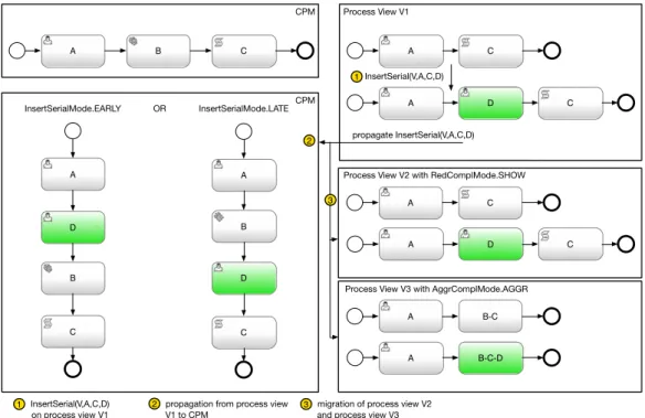
To demonstrate arising ambiguities, Figure 3.4 demonstrates a task insertion.InsertSerial
-(V, D, A, C)adds a taskDbetween taskAand taskCin a process viewV1. Propagating this
change to the associated CPM results in a decision problem: taskB, which was reduced in
process viewV, is present in the CPM. Thus,InsertSerial(V, D, A, C)has to be translated
in either inserting taskDbetween taskAand taskB, or between taskBand taskC. To be
able to solve this ambiguity parameterInsertSerialModedecides, if inserting a task is
executed in immediate vicinity to the most left (EARLY) or most right aligned process nodes
(LATE).
-3.1 Fundamentals on Process Views
Loop, two decisions (for every split gateway) have to be solved. Therefore,
InsertBlock-Modeoffers four values indicating the correct insertion point for the split gateway (EARLY_,
LATE_) and join gateway (_EARLY,_LATE).
After all, associated viewsV2andV3are updated according to their parameters. Automatic
process modelchange propagationto other process views is determined by different
pa-rameters to decide, whether the incoming process model change is shown in other process views or aggregated / reduced accordingly. These parameters also differentiate between
partial (i.e., parametersAggrPartlyMode,RedPartlyMode) and complete intersection
(i.e., parametersAggrComplMode,RedComplMode). The latter can be set to either show
or hide propagated process model changes in other process views associated with the changed CPM. A B C CPM A C Process View V1 A B C D InsertSerialMode.EARLY A D C A B C D InsertSerial(V,A,C,D) propagate InsertSerial(V,A,C,D) InsertSerialMode.LATE A C
Process View V2 with RedComplMode.SHOW
A D C
A B-C
Process View V3 with AggrComplMode.AGGR
A B-C-D CPM 1 2 3 1 InsertSerial(V,A,C,D) 2 3 on process view V1
propagation from process view V1 to CPM
migration of process view V2 and process view V3 OR
Operation Parameter Description InsertSerial(V, n, np, ns, InsertSerialM ode) InsertSerialMode = {EARLY, LATE, PARALLEL}
A new node is inserted as early or late as possible—or parallel to re-duced nodes InsertP arallel(V, n, np, ns, InsertBlockM ode) InsertConditional(V, n, np, ns, InsertBlockM ode) InsertLoop(V, n, np, ns, InsertBlockM ode) InsertBlockMode = {EARLY_EARLY, EARLY_LATE, LATE_EARLY, LATE_EARLY}
Similar to InsertSerialNode, but con-sists of four parameters to adjust an insertion of every gateway (split and join) detached
InsertBranch(V, e, np, ns) Inserts a new branch
DeleteT ask(V, n) DeleteTaskMode =
{LOCAL,
GLOBAL}
Deletes a task only in a view (se-mantically equivalent to RedTask) or in its corresponding CPM
DeleteBranch(V, e) Deletes a branch
DeleteBlock(V, nstart, nend, DeleteBlockM ode)
DeleteBlockMode= {INLINE,
DELETE}
Deletes a block by deleting its sur-rounding gateway nodes and serial-izing all branches in series (INLINE) or deleting the block with all nested nodes
Table 3.2: Control Flow View Update Operations
3.1.4 Migration of Process View Change Sets
All view creation operations in a change set have to be disjunct, i.e., a process node has to be present in no or exactly one node set. One advantage is, that view creation operations can be applied on a process model in arbitrary order.
Change setmigrationsbecome necessary, if any two view creation operations show
inter-secting node sets, or if control flow changes on a CPM are propagated to associated views. A need for migration can be determined by processing all node sets in a change set.
Intersecting node sets can be divided into four scenarios:
• Reduction of a virtual node (i.e.,RedOnAggrscenario)
• Further aggregation of one or more virtual nodes (i.e.,AggrOnAggrscenario)
• Aggregation of process nodes surrounding one or more reduced process nodes (i.e.,
3.1 Fundamentals on Process Views
• Reduction of process nodes surrounding one or more reduced process nodes (i.e.,
RedOnRedscenario)
Solving cut sets of reduced or aggregated process nodes depends on the available view creation operations (cf. Section 3.1.2) and node set type (i.e. dedicated or atomic node sets, cf. Section 3.1.1), because node sets either contain all affected nodes (dedicated node set, used by atomic view create operations) or just entry and exit nodes of an affected SESE block (abstract node set).
RedOnAggrcan always be solved by removing the interfering aggregation operation and
mi-grating all flow nodes contained in the aggregation node set to separate reduction operations. All other scenarios are node set type dependent.
When using dedicated node sets with atomic view creation operations, all overlapping
view creation operations can be easily migrated. ScenarioAggrOnAggrcan be solved
by removing all interfering aggregation operations and include their node set to the new
aggregation operation. When scenarioAggrOnRedoccurs, all involved reduction operation
have to be removed and their node set has to be migrated to the new aggregation operation.
Scenario RedOnRed is not possible when using dedicated node sets, because atomic
creation operations do not cover such case.
Migration onabstract node sets with compound view creation operationsworks similar to
dedicated node sets, but every intersection has to be computed by analyzing a node set
SESE block and either adjustment of a SESE blocks border nodes (i.e.,partial intersection)
or deletion of a complete view creation operation (i.e., complete intersection). Partial
intersections occur, if an affected SESE block of one view creation operation is not fully covered by the other view creation operation’s affected SESE block. If a SESE block
completely surrounds another SESE block, the latter is calledcomplete intersection.
If a change set migration results in an empty node set, the whole view creation operation is deleted, as its application would show no effect.
3.1.5 Process View Refactoring Operations
Applying a creation set on the CPM may create redundant or not necessary control flow
elements, which may be removed by refactoring operations. Refactoring operations are
semantic-preserving, thus, an application on a process model (e.g., a CPM or a process view) does only remove control flow elements beside the point [80]. For example, an application of refactoring operations on a process model in Figure 3.2 has no effect on its process elements, because conditional gateways in a control flow have to be preserved in
order to ensure behavioral equality. In the example, taskC is executed conditionally - by
removing the surrounding gateway block we would create the impression, that taskChas to
be executed on any account.
We focus on three refactoring operations:Simplif yEmptyBranches,Simplif yEmptyBlocks,
andSimplif yM ultipleBlocks(cf. Table 3.3).
A
B
C
A
C Process View with Reduced Tasks *
D E SimplifyMultipleBlocks SimplifyEmptyBranches & SimplifyEmptyBlocks A C b) a) * Reduced tasks are marked dotted
b1 b2 b3 b4 b2 b1
Figure 3.5: Refactoring Operations
Refactoring operationSimplif yEmptyBranchesremoves empty branches of parallel
3.1 Fundamentals on Process Views
Operation Description
Simplif yEmptyBranches(P) Removes empty branches of parallel branching gateways in a process modelP.
Simplif yEmptyBlocks(P) Removes SESE blocks only consisting of a split and a join gateway in a process modelP.
Simplif yM ultipleBlocks(P) Simplifies multiple SESE blocks by condensing nested, directly adjacent gateway nodes of the same type to a SESE block with only two appropriate gateways (i.e., split and join gateway) in process modelP.
Table 3.3: Process View Refactoring Operations
a process model. An empty block is a process fragment of a process model consist-ing of two gateway nodes and their correspondconsist-ing control flows. Refactorconsist-ing operation Simplif yM ultipleBlocksreduces nested, directly adjacent gateway nodes of the same type to a fragment with only one gateway block.
Figure 3.5 illustrates the application of the three refactoring operations on a process view with
reduced tasks: by applyingSimplif yEmptyBranchesin combination withSimplif yEmpty
−Blocks, first, empty branchesb1 andb4, then the outer gateways are removed (cf.
Fig-ure 3.5a). The application of Simplif yM ultipleBlocks leads to a removal of the inner
gateway block, consisting of two parallel gateways, branchb4and taskC, is removed, while
taskCis preserved (cf. Figure 3.5b).
Attention should be paid to branch conditions used with conditional gateways [10]. The
latter splits up a process models control flow byconditions assigned to each branch. At
run-time, the branch to be activated has to be decidable. Therefore, all condition dimen-sions (i.e., dimension of a variable in a condition) are usually covered. An application of Simplif yEmptyBranchesmay remove empty, conditional branches resulting in a loss of a complete dimension coverage. Hence, all remaining branch conditions have to be adjusted to the effect, that the latter cover all condition dimensions.
A software architecture for creating process views is proposed in [40]. It consists of a
visualization engine and a change engine. The visualization engine is responsible for
creating process views, while changes on process views are processed by thechange
engine. Figure 3.6 is divided into a view client, a view server and an underlying PAIS. The client is responsible to render and show process views, while the server manages creation sets and dispatches incoming updates from process view clients. If a view update operation is applied on a process view, first the CPM is updated. Therefore, a process modeling component applies process model changes on the CPM. Second, refactoring operations are
applied on the CPM (cf. Section 3.1.5). Then, all change sets are migrated by a change set component (cf. Section 3.1.4). Finally, changes on the CPM are propagated to all associated views, either by only processing changes, or recreating all views. Different parameters can be set to either process, or discard incoming process model changes (i.e., parameter
{Aggr,Red}PartlyMode, cf. Section 3.1.3). In order to create a process view, the CPM to
be associated is duplicated. Next, the creation set is applied on the process model. Finally, refactoring operations are executed on the process view (cf. Section 3.1.5).
View Client View Server PAIS Visualization V isualization Engine Change Engine Process Modeling Component Refactoring Component Creation Set Component View Client Visualization […] Update CPM Refactoring Migration of CS Creation of Process Model Application of CS Refactoring Component Processing Step visualize change
Figure 3.6: Application Schema for Process Views
3.2 Discussion
Process views, as presented in this section, allow to hide and condense process nodes
based on the creation operationsreductionandaggregation. Additionally, process views may
be updated by respective view update operations (e.g., view creation operationRedT ask).
3.3 Requirements for a BPM-Specific Language
allow process participants to create and update their own process view, while the associated CPM and other process views are held up-to-date.
The approach presented in this section lacks of a CPM-independent description of process views to decouple a creation set from a specific CPM. Instead, a creation set is valid for one specific process model. Additionally, process views are created using a creation set, whose definition follows by dedicating view creation operations. As a consequence, it is not possible
to define process views based on an abstract definition (e.g.,show only tasks a particular
process participant is involved). Additionally, change set migrations are costly, because every time a view operation is executed, their necessity has to be determined by considering all node sets in a change set. Summarizing, there is a need for process view definitions, that may be applicable on arbitrary process models and allow for defining view creation
operations based on aspects (i.e.,show only tasks matching particular conditions).
Furthermore, there is a lack of a comprehensive software implementation for process views supporting CPM-independent definitions. In order to address these issues, the next section shows up requirements for such a CPM-independent language.
3.3 Requirements for a BPM-Specific Language
As discussed in Section 3.2, no approach exists to define process views independently from a specific process model. In addition, process model changes are dependent on a process modeling notation and a PAIS. Hence, they cannot be easily exchanged between them.
Other domains, likerelational database management systems (RDBMS), provide dedicated
languages for data definition and data manipulation (e.g.,Structured Query Language (SQL)
[36]). In particular, SQL is a system independent language for creation, modification, and deletion of data stored in a RDBMS. SQL is able to define new data structures imperatively or refer to existing data by describing changes relational to existing data. In particular, SQL is independent from technical implementations.
SQL is a so-calleddomain-specific language (DSL). In contrast to ageneral-purpose
lan-guage, like the programming language Java, a DSL has limited expressiveness to support one aspect of a domain. If proper implemented, a DSL often offers a higher run-time
efficiency, since it can be implemented more efficiently utilizing specialized optimizations than a general-purpose language [76].
There are two types of DSLs: aninternal DSL is a subset of a general-purpose language
and uses its expression structures. One example is Rails1for Ruby. In contrast, anexternal
DSL is a separate language from the main language of the application it is based on. Thus,
it offers a custom syntax. SQL is an example for anexternal DSL.
A DSL for business process management may solve discussed issues. In the following, requirements for a BPM-specific DSL are outlined (cf. Table 3.4).
A goal of a DSL for process models is to be able to support the BPM lifecycle (cf. Requirement GRQ-1). A generic process modeling notation is required by a DSL to support typical graph-based process modeling notations (cf. Requirement GRQ-2). The DSL should be able to find and retrieve process models stored in a process repository. Therefore, search expressions offer the ability to find process models (cf. Requirement GRQ-3). A resulting requirement for process data discovery are dependency representations defining, how search expressions may define relations between different process models and process elements (cf. Requirement MRQ-2).
In order to ensure a mapping between any process modeling notation and the DSL’s process modeling notation, an underlying meta-model of the DSL has to be able to describe any type of business process (cf. Requirement MRQ-1). A modular concept should enable extensibility of supported process modeling notations, process model change operations, and the DSL’s internal processing (cf. Requirement GRQ-5).
Process elements discovered by the DSL should be updatable. Therefore, operations to change and store an updated process model should be provided by the DSL (cf. Require-ments MRQ-3 and MRQ-6). Provided operations should only apply changes supported by the initial process modeling notation. Therefore, the DSL has to be able examining their expressiveness (cf. Requirement MRQ-4). Often companies with large process models require complex operations managing these models, which should also be definable and applicable by the DSL (cf. Requirement MRQ-5). The DSL should support process views based on view creation operations and custom process view definitions to simplify managing
3.4 Summary
and displaying those large process models (cf. Requirements VRQ-1 and VRQ-2). Updates on created process views further simplify their handling and, thus, should also be supported (cf. Requirement VRQ-3).
3.4 Summary
This section introduces process views, which abstract process models by only showing necessary process elements in order to simplify the handling of large business processes with dozen of process elements. Hence, process nodes may be aggregated or reduced. Arising problems, when applying these view creation operations, are solved by utilizing refactoring operations and change set migrations. Additionally, process views may be changed by applying view update operations. Process models related to a process view are automatically adjusted to keep these models consistent.
Currently, no approach exists for a process model independent definition of process views. Furthermore, a creation and update of process models is dependent from a process modeling notation and PAIS. In this section requirements for a BPM-specific language were verbalized. These include proposals to enable process data discovery, generic process model definitions, process views, and interoperability with any PAIS.
Requirement Description General Requirements
GRQ-1 Support Complete BPM Lifecycle The DSL should enable full support for every BPM lifecycle phase.
GRQ-2 Generic Process Modeling Notation Introduction of a generic process modeling notation, which is able to represent ideally each graph-based process notation. GRQ-3 Process Data Discovery Find process models based on search expressions, like
process similarities.
GRQ-4 Correctness The DSL should provide correctness checks and abilities to define conditions process models have to comply with. Addi-tionally, arising ambiguities during process model changes should be solved automatically, the application of change operations corrupting a process model should be prevented. GRQ-5 Modularity The DSL’s expressiveness has to be extensible, which com-prises the internal processing, supported process modeling notations, search and process model change operations. GRQ-6 Interoperability The DSL should be defined independently from a specific
PAIS.
GRQ-7 Graph Processing Operations The DSL should provide graph processing operations ap-plicable on its meta-model implementing common graph algorithms (e.g., calculation of predecessors and succes-sors of a process node). Graph processing operations may be used by all DSL-provided operations (cf. Requirement MRQ-3) or supplied extensions (cf. Requirement GRQ-5). Process Modeling Requirements
MRQ-1 Process Model Definition The DSL should be able to declare process landscapes, process models, process fragments, and process elements. MRQ-2 Dependency Representation The DSL should allow to express dependencies between different process models, fragments and process elements. This functionality is, for example, a condition for requirement GRQ-5.
MRQ-3 Process Model Change Changes on process models should be supported by the DSL.
MRQ-4 Process Model Expressiveness An approach to describe a process notations cardinality has to be provided by the DSL. This requirement is needed to check for compatibility with process model changes (cf. Requirement MRQ-3).
MRQ-5 Custom Process Model Change Definition The DSL should allow for custom process model change def-initions. Therefore, custom process model changes should be able to utilize all DSL-supplied operations.
MRQ-6 Persistence Behavior Manipulation Allow to modify processing between the PQL framework and any PAIS.
Process View Requirements
VRQ-1 Process View Creation Process view creation operations have to be supported by the DSL (cf. Section 3.1.2).
VRQ-2 Custom View Creation Definition The DSL should allow for custom view creation operations. Therefore, the latter should be able to utilize all DSL-supplied process view creation operations.
VRQ-3 Updates on Process Views Process view update operations have to be supported by the DSL (cf. Section 3.1.3).
4
Process Query and Modification
Language
Companies often have dozen of process models, which have to be up-to-date. Various PAISs across a companies IT infrastructure complicate changes on process models, which may be shared across different PAIS. Furthermore, every PAIS supports different sets of process modeling notations and implements methods changing process models in a different manner.
In the following the Process Query Language (PQL), a simple data definition and data
manipulation language "for BPM needs" is introduced, based on requirements verbalized in section 3.3. PQL supports the definition of process models and process views, changes on process models and process views and is able to discover and retrieve process models from process repositories. PQL may be used as query language embedded in a
request-response1 protocol, as configuration language to define process model changes or as generic interchange format for process models.
Section 4.1 describes the PQL meta-model required to support process modeling notation-independent changes on process models. Furthermore, concepts to ensure a process models correctness are presented. Section 4.2 describes concepts of PQL including the PQL meta-model, operations to change process models, concepts enabling discovery of process models in a process repository, or the definition of process views. Section 4.3 introduces a software architecture supporting PQL. Section 4.4 concludes this chapter.
4.1 PQL Process Meta-Model
To comply with requirement GRQ-2 (i.e., generic process model representation), process models may be either described by a generic process model or by a pre-processed data structure, like a process structure tree.
In [75] a generic meta-model is proposed, which divides a process model in the perspectives:
functional, behavioral, organizational and informational (cf. Table 4.2). Aprocess definition
P D based on such a meta-model is defined by a tupleP D = (Elements, ControlF low,
P rocessLogic). SetElementsconsists of process elements describing a non-behavioral perspective (i.e., tasks, process participants, or process data elements). Furthermore, setControlF lowcomprises behavioral process elements, i.e.,operatorsandconnections. Operators denote process elements influencing a control flow (i.e., gateways), while
con-nections describe control and data flow edges. Finally, setP rocessLogicdefines relations
between behavioral and non-behavioral elements.
Converting process models of different process modeling notations into a generic process modeling notation and vice versa might be complicated due to different process elements [38]. For example, exclusive split gateways of a control flow are described by different process elements. Furthermore, exclusive gateway conditions may also have different representations depending on the process modeling notation. Particularly, the latter can be described by different script languages, i.e., UEL or JavaScript. However, automatic
4.1 PQL Process Meta-Model Attribute Description
Generic Attributes
identifier Identifies a particular process element from others, has to be unique (e.g., identifier="nid4"). name* Name of a process element presented to a process participant (e.g., name="Store Invoice"). extensions* Set of attributes to store additional information, for example, process data values (i.e., if a
process node class is INFORMATIONAL) or a human-readable documentation for a task (e.g., extensions={documentation="Stores the created invoice in the database."}).
Node Attributes
nodeClass Distinguishes between tasks, control flow modifying nodes and additional entities (like process participants and process data elements). Send and receive events are distinguished based on LINK edge directions. Possible values are:
FUNCTIONAL: process tasks
BEHAVIORAL: gateway and event representation ORGANIZATIONAL: process participants
INFORMATIONAL: process data element representation
nodeType Further distinguishes a node class into different node types. Attribute nodeType is dependent from nodeClass. Possible values are:
FUNCTIONAL: USER (involves a human), SERVICE (executed by a external service), SYSTEM (executed by the PAIS)
BEHAVIORAL: AND,OR,XOR,EVENT ORGANIZATIONAL: ENTITY, GROUP INFORMATIONAL: not applicable Edge Attributes
edgeClass An edge class defines, whether edges are behavioral-relevant (control flow) or denote relations between entities (organizational, informational nodes). Possible values are:
FLOW: connects FUNCTIONAL and/or BEHAVIORAL nodes
LINK: connects ORGANIZATIONAL and/or INFORMATIONAL nodes with FUNCTIONAL and/or BEHAVIORAL nodes
edgeType* Classifies edges more precisely. Attribute edgeType is implementation-dependent.
* Attribute is optional
Table 4.1: PQL Meta-Model Element Attributes
conversion of semantical meanings is a far complex topic and is not further discussed in this thesis.
The PQL process meta-model is a directed graph consisting of nodes and edges. Each node and each edge has respective attributes, which describe, for example, its functional
behavior. Each node has a set ofelement attributes, which can be mapped to a certain
process models notation (cf. Table 4.1). Element attributes are mandatory in order to ensure, that changes on process models defined by PQL have sufficient information to be executed unambiguously. Furthermore, the set of element attributes must be extendable to cover
the complete cardinality of a process modeling notation. Custom element attributes are
PAIS-specific and can only be covered by providing operations to define and modify these additional attributes.
Table 4.1 shows PQL element attributes comprising all perspectives presented in Table 4.2. Additional perspectives, like time, error, or operation (e.g., process instance behavior), are not considered.
Every instantiation of a meta-model element is assigned to generic attributes, which are
mandatory in order to identify nodes and edges unambiguously. Node-specific attributes
comprise attributes node class and node type. Attribute node class offers a high-level
classification of process nodes, which is necessary to identify nodes by their functionality
(e.g., BPMN 2.0 tasks are represented byFUNCTIONALnodes). Node types are used, for
example, to distinguish between different task types (e.g., user and service tasks). Edges
are divided into classes and types as well: edge classFLOWdenotes a control flow, edge
classLINKdescribes data or message flows between process nodes. Edges are directed
and may influence the semantics of a node: aLINKedge leaving aBEHAVIORALnode with
node typeEVENTdenotes the process node as message-throwing event.
Process participants are representable by nodes having attribute valueORGANIZATIONAL
for attribute node class. To define dependencies between process participants and nodes of
typeFUNCTIONAL, an organizational node can be linked to a functional node by an edge
with edge classLINK. This method does not differentiate between process participants
allowed to execute a task or designated participants. In order to define a fine granular
relationship between participants and tasks, attributeedge typemay be used. This attribute
is PAIS-specific, standard operations provided by PQL only take edge classes into account, but can be overwritten or extended accordingly (cf. Section 4.2.4).
Organizational and informational perspectives are represented by nodes to avoid redundan-cies and ambiguous identification of such elements. These nodes may be also represented by adding additional attributes to functional and behavioral nodes, e.g., an attribute of a process participant designated to execute a specific task. However, this increases, for example, the effort to identify a process participant’s designated tasks, because each node defining this attribute has to be considered. Additionally, view creation algorithms can be implemented more efficiently, as affected nodes are identified by following all links instead of exploring a process model’s whole set of process nodes. For example, if we want to reduce all tasks in a process view where a specific process participant is not involved in, every task in a process model’s node set has to be treated and checked (i.e., if this task contains an attribute describing the process participants involvement). By defining a process participant