Data-Over-Cable Service Interface Specifications
Downstream RF Interface Specification
CM-SP-DRFI-I07-081209
ISSUED
Notice
This DOCSIS specification is the result of a cooperative effort
undertaken at the direction of Cable Television Laboratories, Inc. for the benefit of the cable industry and its customers. This document may contain references to other documents not owned or controlled by CableLabs. Use and understanding of this document may require access to such other documents. Designing, manufacturing, distributing, using, selling, or servicing products, or providing services, based on this document may require intellectual property licenses from third parties for technology referenced in this document.
Neither CableLabs nor any member company is responsible to any party for any liability of any nature whatsoever resulting from or arising out of use or reliance upon this document, or any document referenced herein. This document is furnished on an "AS IS" basis and neither CableLabs nor its members provides any representation or warranty, express or implied, regarding the accuracy, completeness,
noninfringement, or fitness for a particular purpose of this document, or any document referenced herein.
© Copyright 2005 - 2008 Cable Television Laboratories, Inc. All rights reserved.
Document Status Sheet
Document Control Number: CM-SP-DRFI-I07-081209Document Title: Downstream RF Interface Specification Revision History: I01 – Released 08/05/05
I02 – Released 12/09/05 I03 – Released 01/06/06 I04 – Released 12/22/06 I05 – Released 02/23/07 I06 – Released 02/15/08 I07 – Released 12/09/08 Date: December 9, 2008 Status: Work in Progress
Draft Issued Closed Distribution Restrictions: Author
Only CL/Member CL/ Vendor Member/ Public
Key to Document Status Codes:
Work in Progress An incomplete document, designed to guide discussion and generate feedback that may include several alternative requirements for consideration.
Draft A document in specification format considered largely complete, but lacking review by Members and vendors. Drafts are susceptible to substantial change during the review process.
Issued A stable document, which has undergone rigorous member and vendor review and is suitable for product design and development, cross-vendor interoperability, and certification testing.
Closed A static document, reviewed, tested, validated, and closed to further engineering change requests to the specification through CableLabs.
Trademarks
CableLabs®, DOCSIS®, EuroDOCSIS™, eDOCSIS™, M-CMTS™, PacketCable™, EuroPacketCable™,
PCMM™, CableHome®, CableOffice™, OpenCable™, OCAP™, CableCARD™, M-Card™, DCAS™, tru2way™,
Contents
1 SCOPE AND PURPOSE ...1
1.1 SCOPE...1 1.2 PURPOSE OF DOCUMENT...2 1.3 ORGANIZATION OF DOCUMENT...2 1.4 REQUIREMENTS...2 2 REFERENCES...3 2.1 NORMATIVE REFERENCES...3 2.2 INFORMATIVE REFERENCES...3 2.3 REFERENCE ACQUISITION...4
3 TERMS AND DEFINITIONS ...5
4 ACRONYMS AND ABBREVIATIONS ...7
5 FUNCTIONAL ASSUMPTIONS ...8
5.1 BROADBAND ACCESS NETWORK...8
5.2 EQUIPMENT ASSUMPTIONS...8
5.2.1 Frequency Plan...8
5.2.2 Compatibility with Other Services ...8
5.2.3 Fault Isolation Impact on Other Users ...9
5.3 DOWNSTREAM PLANT ASSUMPTIONS...9
5.3.1 Transmission Levels...9
5.3.2 Frequency Inversion ...9
5.3.3 Analog and Digital Channel Line-up...9
5.3.4 Analog Protection Goal ...9
6 PHYSICAL MEDIA DEPENDENT SUBLAYER SPECIFICATION...10
6.1 SCOPE...10
6.2 EDGEQAM(EQAM) DIFFERENCES FROM CMTS ...10
6.3 DOWNSTREAM...11
6.3.1 Downstream Protocol ...11
6.3.2 Spectrum Format ...11
6.3.3 Scaleable Interleaving to Support Video and High-Speed Data Services...11
6.3.4 Downstream Frequency Plan ...12
6.3.5 DRFI Output Electrical ...12
6.3.6 CMTS or EQAM Clock Generation ...18
6.3.7 Downstream Symbol Clock Jitter for Synchronous Operation ...19
6.3.8 Downstream Symbol Clock Drift for Synchronous Operation...19
6.3.9 Timestamp Jitter ...19
7 DOWNSTREAM TRANSMISSION CONVERGENCE SUBLAYER ...21
7.1 INTRODUCTION...21
7.2 MPEGPACKET FORMAT...21
7.3 MPEGHEADER FOR DOCSISDATA-OVER-CABLE...21
7.4 MPEGPAYLOAD FOR DOCSISDATA-OVER-CABLE...22
7.4.1 stuff_byte...22
7.4.2 pointer_field...22
7.5 INTERACTION WITH THE MACSUBLAYER...23
ANNEX A ADDITIONS AND MODIFICATIONS FOR EUROPEAN SPECIFICATION...25
A.1 SCOPE AND PURPOSE...25
A.2 REFERENCES...25
A.2.1 Normative References ...25
A.3 TERMS AND DEFINITIONS...25
A.4 ACRONYMS AND ABBREVIATIONS...25
A.5 FUNCTIONAL ASSUMPTIONS...25
A.5.1 Broadband Access Network ...26
A.5.2 Equipment Assumptions...26
A.5.3 Downstream Plant Assumptions ...26
A.6 PHYSICAL MEDIA DEPENDENT SUBLAYER SPECIFICATION...27
A.6.1 Scope...27
A.6.2 EdgeQAM (EQAM) differences from CMTS...27
A.6.3 Downstream...27
A.7 DOWNSTREAM TRANSMISSION CONVERGENCE SUBLAYER...34
A.7.1 Introduction ...34
A.7.2 MPEG Packet Format ...34
A.7.3 MPEG Header for DOCSIS Data-Over-Cable ...34
A.7.4 MPEG Payload for DOCSIS Data-Over-Cable...34
A.7.5 Interaction with the MAC Sublayer ...34
A.7.6 Interaction with the Physical Layer ...34
ANNEX B DOCS-DRF-MIB (NORMATIVE)...35
APPENDIX I ACKNOWLEDGEMENTS (INFORMATIVE) ...51
APPENDIX II REVISION HISTORY (INFORMATIVE) ...52
II.1 ENGINEERING CHANGES FOR CM-SP-DRFI-I02-051209...52
II.2 ENGINEERING CHANGES FOR CM-SP-DRFI-I03-060106...52
II.3 ENGINEERING CHANGE FOR CM-SP-DRFI-I04-061222 ...52
II.4 ENGINEERING CHANGE FOR CM-SP-DRFI-I05-070223 ...52
II.5 ENGINEERING CHANGE FOR CM-SP-DRFI-I06-080215 ...52
Figures
FIGURE 6–1-LOGICAL VIEW OF MODULAR CMTS AND INTERFACES...10
FIGURE 7–1-EXAMPLE OF INTERLEAVING MPEGPACKETS IN DOWNSTREAM...21
FIGURE 7–2-FORMAT OF AN MPEGPACKET...21
FIGURE 7–3-PACKET FORMAT WHERE A MACFRAME IMMEDIATELY FOLLOWS THE POINTER FIELD...23
FIGURE 7–4-PACKET FORMAT WITH MACFRAME PRECEDED BY STUFFING BYTES...23
FIGURE 7–5-PACKET FORMAT SHOWING MULTIPLE MACFRAMES IN A SINGLE PACKET...23
FIGURE 7–6-PACKET FORMAT WHERE A MACFRAME SPANS MULTIPLE PACKETS...23
Tables
TABLE 6–1-LOW LATENCY INTERLEAVER DEPTHS...11TABLE 6–2-LONG DURATION BURST NOISE PROTECTION INTERLEAVER DEPTHS...12
TABLE 6–3-RFOUTPUT ELECTRICAL REQUIREMENTS...13
TABLE 6–4-DRFIDEVICE OUTPUT POWER...14
TABLE 6–5-EQAM OR CMTSOUTPUT OUT-OF-BAND NOISE AND SPURIOUS EMISSIONS REQUIREMENTS...17
TABLE 6–6-DOWNSTREAM SYMBOL RATES & PARAMETERS FOR SYNCHRONIZATION WITH MASTER CLOCK...19
TABLE 7–1-MPEGHEADER FORMAT FOR DOCSISDATA-OVER-CABLE PACKETS...22
TABLE A–1-INTERLEAVER CHARACTERISTICS...27
TABLE A–2-OUTPUT ELECTRICAL REQUIREMENTS PER RFPORT...28
TABLE A–3-DRFIDEVICE OUTPUT POWER...29
TABLE A–4-EQAM OR CMTSOUTPUT OUT-OF-BAND NOISE AND SPURIOUS EMISSIONS REQUIREMENTS ...31
1 SCOPE AND PURPOSE
1.1 Scope
This document defines the downstream radio-frequency interface [DRFI] specifications for:
• an edgeQAM (EQAM) modular device, or
• an integrated Cable Modem Termination System [CMTS] with multiple downstream channels per RF port, or • an integrated CMTS beyond DOCSIS 2.0.
There are differences in the cable spectrum planning practices adopted for different networks in the world. Therefore two options for physical layer technology are included, which have equal priority and are not required to be
interoperable. One technology option is based on the downstream multi-program television distribution that is deployed in North America using 6 MHz channeling. The other technology option is based on the corresponding European multi-program television distribution. Both options have the same status, notwithstanding that the document structure does not reflect this equal priority. The first of these options is defined in Sections 5, 6, 7, whereas the second is defined by replacing the content of those sections with the content of Annex A.
Correspondingly, [ITU-T J.83-B] and [CEA-542-B] apply only to the first option, and [EN 300 429] only to the second. Compliance with this document requires compliance with the one or the other of these implementations, not with both. It is not required that equipment built to one option shall interoperate with equipment built to the other. A DRFI-compliant device may be a single-channel only device, or it may be a multiple-channel device capable of generating one or multiple downstream RF carriers simultaneously on one RF output port. An EQAM may be a module of a modular cable modem termination system (M-CMTS) and be used for delivering a high-speed data service or it may serve as a component of a digital video or video-on-demand (VOD) system, delivering high quality digital video to subscribers. These specifications are crafted to enable an EQAM to be used without restriction in either or both service delivery scenarios simultaneously. “Simultaneous” in the early deployments means that if a RF output port has multiple QAM channels, some channel(s) may be delivering high-speed data while some other channel(s) may be delivering digital video. This specification enables future uses, wherein a single QAM channel may share bandwidth between high-speed data and digital video in the same MPEG transport stream.
Conceptually, an EQAM will accept input via an Ethernet link, integrate the incoming data into an MPEG transport stream, modulate one of a plurality of RF carriers, per these specifications, and deliver the carrier to a single RF output connector shared in common with all modulators. Conceivably, a single EQAM RF channel could be used for data and video simultaneously. The reason that an EQAM RF channel can be used for either is that both digital video and DOCSIS data downstream channels are based on ITU-T J.83 Annex B [ITU-T J.83-B] for cable networks in North America and EN 300 429 [EN 300 429] for cable networks deployed in Europe. On downstream channels complying to ITU-T J.83, Annex B, typically, the only difference between an EQAM RF channel operating in a video mode and an EQAM RF channel operating in DOCSIS data mode is the interleaver depth (see Sections 6.3.1 and 6.3.3). DOCSIS data runs in a low latency mode using a shallow interleaver depth at the cost of some burst protection. DOCSIS data can do this because if a transmission error occurs, the higher layer protocols will request re-transmission of the missing data. For video, the sequence of frames in the program is both time sensitive and order sensitive and cannot be re-transmitted. For this reason, video uses a deeper interleaver depth to provide more extensive burst protection and deliver more of the program content without loss. The penalty video pays is in latency. The entire program content is delayed by a few milliseconds, typically, and is invisible to the viewers of the program. The conflicting demands for interleaver depth are what prevent a single EQAM RF channel from being used optimally for video and DOCSIS data simultaneously. A traditional integrated CMTS, however, is used solely for DOCSIS data.
The specifications were developed by Cable Television Laboratories (CableLabs) for the benefit of the cable industry. These specifications are mostly comprised of contributions from operators and vendors throughout the world.
1.2 Purpose of Document
The purpose of this document is to define the RF characteristics required in the downstream transmitter(s) of CMTSs and EQAMs, sufficiently enough to permit vendors to build devices that meet the needs of CableLabs multiple system operators (MSOs) around the world. Such devices implementing the first technology option can be submitted to CableLabs for qualification testing in conjunction with one or several vendor’s compatible components, while a certification scheme for devices compliant to the second technology option is managed by EuroCableLabs. This level of multi-vendor interoperability is a critical measure of our ability to achieve the purpose of this document.
1.3 Organization of Document
This document will not attempt to wholly replicate the normative references provided in the document. However, it will use extracted portions of said documents where it adds clarity to this document. For fuller understanding of this document, the most recent versions of [ITU-T J.83-B] Annex B or [EN 300 429], respectively, as well as
[DOCSIS2] should be available for reference.1
1.4 Requirements
Throughout this document, the words that are used to define the significance of particular requirements are capitalized. These words are:
“MUST” or “SHALL” This word or the adjective “REQUIRED” means that the item is an absolute
requirement of this specification.
“MUST NOT” or “SHALL NOT” This phrase means that the item is an absolute prohibition of this specification.
“SHOULD” This word or the adjective “RECOMMENDED” means that there may exist
valid reasons in particular circumstances to ignore this item, but the full implications should be understood and the case carefully weighed before choosing a different course.
“SHOULD NOT” This phrase means that there may exist valid reasons in particular
circumstances when the listed behavior is acceptable or even useful, but the full implications should be understood and the case carefully weighed before implementing any behavior described with this label.
“MAY” This word or the adjective “OPTIONAL” means that this item is truly
optional.One vendor may choose to include the item because a particular marketplace requires it or because it enhances the product, for example; another vendor may omit the same item.
2 REFERENCES
2.1 Normative References
2In order to claim compliance with this specification, it is necessary to conform to the following standards and other works as indicated, in addition to the other requirements of this specification. Notwithstanding, intellectual property rights may be required to use or implement such normative references.
[DOCSIS2] Data-Over-Cable Service Interface Specifications, Radio Frequency Interface Specification v2.0, CM-SP-RFIv2.0-C01-081104, November 4, 2008, Cable Television Laboratories, Inc. [CEA-542-B] CEA-542-B: "CEA Standard: Cable Television Channel Identification Plan," July 2003. [ANSI/SCTE 02] ANSI/SCTE 02 2006, "Specification for F Port, Female, Indoor."
[ITU-T J.83-B] Annex B to ITU-T Rec. J.83 (12/07), "Digital multi-programme systems for television sound and data services for cable distribution."
[ISO 13818] ISO/IEC 13818-1, "Information Technology – Generic Coding of Moving Pictures and Associated Audio: Systems / ITU-T Rec. H.222.0," 2007.
2.2 Informative References
This specification uses the following informative references.
[NSI] CMTS Network Side Interface, SP-CMTS-NSI-I01-960702, July 2, 1996, Cable Television
Laboratories, Inc.
[M-OSSI] Modular CMTS Operation Support System Interface, CM-SP-M-OSSI-I08-081209,
December 9, 2008, Cable Television Laboratories, Inc.
[CMCI] Cable Modem CPE Interface, CM-SP-CMCI-C01-081104, November 4, 2008, Cable
Television Laboratories, Inc.
[DEPI] Downstream External-PHY Interface, CM-SP-DEPI-I06-081209, December 9, 2008, Cable
Television Laboratories, Inc.
[DTI] DOCSIS Timing Interface, CM-SP-DTI-I06-081209, December 9, 2008, Cable Televisions
Laboratories, Inc.
[ERMI] Edge Resource Manager Interface, CM-SP-ERMI-I03-081107, November 7, 2008, Cable
Television Laboratories, Inc.
2.3 Reference Acquisition
• Cable Television Laboratories, Inc., http://www.cablelabs.com/
• EIA: Electronic Industries Al
• ETSI: European Telecommunications Standards Institute, http://www.etsi.org/services_products/freestandard/home.htm
• ITU: International Telecommunication Union (ITU), http://www.itu.int/home/contact/index.html
• ISO: International Organization for Standardization
3 TERMS AND DEFINITIONS
This specification uses the following terms:3
Ceiling (ceil) Returns the first integer that is greater than or equal to a given value.
CM Cable Modem. A modulator-demodulator at subscriber locations intended for use in
conveying data communications on a cable television system.
CPE Customer Premises Equipment. Equipment at the end user’s premises; may be provided by
the service provider.
Carrier-to-Noise Ratio
(C/N or CNR)
Carrier-to-Noise Ratio.The ratio of signal power to noise power in a defined measurement bandwidth. For digital modulation, CNR = Es/No, the energy-per symbol to noise-density ratio; the signal power is measured in the occupied bandwidth, and the noise power is normalized to the modulation-rate bandwidth. For analog NTSC video modulation, the noise measurement bandwidth is 4 MHz.
Decibels (dB) Ratio of two power levels expressed mathematically as dB = 10log10(POUT/PIN).
Decibel-Millivolt (dBmV)
Unit of RF power expressed in decibels relative to 1 millivolt over 75 ohms, where dBmV = 20log10(value in mV/1 mV).
Electronic Industries Alliance (EIA)
A voluntary body of manufacturers which, among other activities, prepares and publishes standards.
EQAM EdgeQAM modulator. A head end or hub device that receives packets of digital video or
data. It re-packetizes the video or data into an MPEG transport stream and digitally modulates the digital transport stream onto a downstream RF carrier using quadrature amplitude modulation (QAM).
FEC Forward Error Correction. A class of methods for controlling errors in a communication
system. FEC sends parity information with the data which can be used by the receiver to check and correct the data.
Gigahertz (GHz) A unit of frequency; 1,000,000,000 or 109 Hz. Hertz (Hz) A unit of frequency; formerly cycles per second.
HRC Harmonic Related Carriers. A method of spacing channels on a cable television system with
all carriers related to a common reference.
HFC Hybrid Fiber/Coax System. A broadband bidirectional shared-media transmission system
using optical fiber trunks between the head-end and the fiber nodes, and coaxial cable distribution from the fiber nodes to the customer locations.
IRC Incremental Related Carriers. A method of spacing NTSC television channels on a cable
television system in which all channels are offset up 12.5 kHz with respect to the [CEA-542-B] standard channel plan except for channels 5 and 6.
kilohertz (kHz) Unit of frequency; 1,000 or 103 Hz; formerly kilocycles per second. Media Access
Control (MAC)
Used to refer to the layer 2 element of the system which would include DOCSIS framing and signaling.
Megahertz (MHz)
A unit of frequency; 1,000,000 or 106 Hz; formerly megacycles per second.
MER Modulation Error Ratio. The ratio of the average symbol power to average error power.
M/N Relationship of integer numbers M,N that represents the ratio of the downstream symbol
clock rate to the DOCSIS master clock rate.
Multiple System Operator (MSO)
A corporate entity that owns and/or operates more than one cable system.
NTSC National Television Systems Committee. Committee which defined the analog, color
television, broadcast standards in North America. The standards television 525-line video format for North American television transmission is named after this committee.
NGNA LLC Company formed by cable operators to define a next-generation network architecture for
future cable industry market and business requirements.
Physical Media Dependent Sublayer (PMD)
A sublayer of the Physical layer which is concerned with transmitting bits or groups of bits over particular types of transmission link between open systems and which entails electrical, mechanical and handshaking procedures.
QAM channel (QAM ch)
Analog RF channel that uses quadrature amplitude modulation (QAM) to convey information.
Quadrature Amplitude Modulation (QAM)
A modulation technique in which an analog signal’s amplitude and phase vary to convey information, such as digital data.
Radio
Frequency (RF)
A portion of the electromagnetic spectrum from a few kilohertz to just below the frequency of infrared light.
Radio Frequency Interface (RFI)
Term encompassing the downstream and the upstream radio frequency interfaces.
Root Mean Square (RMS)
Square root of the mean value squared a function.
Self-Aggregation Method used to compute the headend noise floor by summing measured noise from a single
device over a specified output frequency range.
Standard Channel Plan (STD)
Method of spacing NTSC television channels on a cable television system defined in [CEA-542-B].
Upstream Channel Descriptor (UCD)
The MAC Management Message used to communicate the characteristics of the upstream physical layer to the cable modems.
Video on Demand (VoD)
System that enables individuals to select and watch video content over a network through an interactive television system.
4 ACRONYMS AND ABBREVIATIONS
This specification uses the following terms:
CMCI Cable Modem CPE Interface CMTS Cable Modem Termination System
CW Continuous Wave
dBc Decibels relative to carrier power
DEPI Downstream External-PHY Interface
DOCSIS Data-Over-Cable Service Interface Specifications DRFI Downstream Radio Frequency Interface
DTI DOCSIS Timing Interface
ERMI Edge Resource Manager Interface
FCC Federal Communications Commission
ISO International Standards Organization
ITU International Telecommunications Union
ITU-T Telecommunication Standardization Sector of the ITU M-CMTS Modular Cable Modem Termination System
Ms Millisecond. 10-3 second
MPEG Moving Picture Experts Group
Ns Nanosecond. 10-9 second
NGNA Next Generation Network Architecture, see NGNA LLC
OSSI Operations System Support Interface
PHY Physical Layer
ppm Parts per Million
Q Quadrature modulation component
5 FUNCTIONAL ASSUMPTIONS
This section describes the characteristics of a cable television plant, assumed to be for the purpose of operating a data-over-cable system. It is not a description of EQAM or CMTS parameters. The data-over-cable system MUST be interoperable within the environment described in this section.
Whenever there is a reference in this section to frequency plans or compatibility with other services, or conflicts with any legal requirement for the area of operation, the latter shall take precedence. Any reference to NTSC analog signals in six MHz channels does not imply that such signals are physically present.
5.1 Broadband Access Network
A coaxial-based broadband access network is assumed. This may take the form of either an all-coax or hybrid fiber/coax (HFC) network. The generic term “cable network” is used here to cover all cases.
A cable network uses a shared-medium, “tree-and-branch” architecture, with analog transmission. The key functional characteristics assumed in this document are the following:
• Two-way transmission
• A maximum optical/electrical spacing between the DRFI-compliant device and the most distant CM of 100 miles in each direction, although typical maximum separation may be 10-15 miles
• A maximum differential optical/electrical spacing between the DRFI-compliant device and the closest and most distant modems of 100 miles in each direction, although this would typically be limited to 15 miles
At a propagation velocity in fiber of approximately 1.5 ns/ft, 100 miles of fiber in each direction results in a round-trip delay of approximately 1.6 ms. For further information, see [DOCSIS2], Appendix VIII.
5.2 Equipment Assumptions
5.2.1 Frequency Plan
In the downstream direction, the cable system is assumed to have a pass band with a lower edge between 50 and 54 MHz and an upper edge that is implementation-dependent but is typically in the range of 300 to 870 MHz. Within that pass band, NTSC analog television signals in six-MHz channels are assumed present on the Standard (STD), HRC, or IRC frequency plans of [CEA-542-B], as well as other narrowband and wideband digital signals.
5.2.2 Compatibility with Other Services
The CM and EQAM or CMTS MUST coexist with the other services on the cable network, for example:
1. They MUST be interoperable in the cable spectrum assigned for EQAM or CMTS-CM interoperation, while the balance of the cable spectrum is occupied by any combination of television and other signals,and
2. They MUST NOT cause harmful interference to any other services that are assigned to the cable network in spectrum outside of that allocated to the EQAM or CMTS. The latter is understood as:
• No measurable degradation (highest level of compatibility),
• No degradation below the perceptible level of impairments for all services (standard or medium level of compatibility), or
• No degradation below the minimal standards accepted by the industry (for example, FCC for analog video services) or other service provider (minimal level of compatibility).
5.2.3 Fault Isolation Impact on Other Users
As downstream transmissions are on a shared-media, point-to-multipoint system, fault-isolation procedures should take into account the potential harmful impact of faults and fault-isolation procedures on numerous users of the data-over-cable, video, and other services.
For the interpretation of harmful impact, see Section 5.2.2 above.
5.3 Downstream Plant Assumptions
The DRFI specifications have been developed with the downstream plant assumptions of this section.
5.3.1 Transmission Levels
The nominal power level of the downstream RF signal(s) within a six-MHz channel (average power) is targeted to be in the range: -10 dBc to -6 dBc, relative to analog video carrier level (peak power) and will normally not exceed analog video carrier level.
5.3.2 Frequency Inversion
There will be no frequency inversion in the transmission path in either the downstream or the upstream directions (i.e., a positive change in frequency at the input to the cable network will result in a positive change in frequency at the output).
5.3.3 Analog and Digital Channel Line-up
In developing this specification, it was assumed that a maximum of 119 digital channels would be deployed in a headend. For the purposes of calculating CNR, protection for analog channels, it was assumed that analog channels are placed at lower frequencies in the channel line-up, versus digital channels.
5.3.4 Analog Protection Goal
One of the goals of the DRFI specification is to provide the minimum intended analog channel CNR protection of 60 dB for systems deploying up to 119 DRFI-compliant QAM channels.
The specification assumes that the transmitted power level of the digital channels will be 6 dB below the peak envelope power of the visual signal of analog channels, which is the typical condition for 256 QAM transmission. It is further assumed that the channel lineup will place analog channels at lower frequencies versus digital channels. An adjustment of 10*log10 (6 MHz / 4 MHz) is used to account for the difference in noise bandwidth of digital
channels versus analog channels. With the assumptions above, for a 119 QAM channel system, the specification in Item 5 of Table 6–5 equates to an analog CNR protection of 60dB.
6 PHYSICAL MEDIA DEPENDENT SUBLAYER SPECIFICATION
6.1 Scope
This section applies to the first technology option referred to in Section 1.1. For the second option, refer to Annex A. This specification defines the electrical characteristics of the Downstream Radio Frequency Interface (DRFI) of a cable modem termination system (CMTS) or an edgeQAM (EQAM). It is the intent of this specification to define an interoperable DRFI-compliant device, such that any implementation of a CM can work with any EQAM or CMTS. It is not the intent of this specification to imply any specific implementation. Figure 6–1 shows the M-CMTS structure and interfaces.
Whenever a reference in this section to spurious emissions conflicts with any legal requirement for the area of operation, the latter shall take precedence.
M-CMTS M-CMTS Core EQAM Upstream Receiver DOCSIS Timing Server Wide Area Network Network Side Interface (NSI) Operations Support Systems Interface (OSSI) Cable Modem to CPE Interface (CMCI) Downstream External-Phy Interface (DEPI) DOCSIS Timing Interface (DTI) Edge Resource Management Interfaces (ERMI) Downstream RF Interface (DRFI) Cable Modem (CM) Operations Support System Edge Resource Manager Customer Premises Equipment (CPE) Radio Frequency Interface (RFI) HE Combining / Hybrid Fiber-Coax Network (HFC) M-CMTS Interface Other DOCSIS Interface
Figure 6–1 - Logical View of Modular CMTS and Interfaces
The CMTS Network Side Interface [NSI], Modular CMTS Operation Support System Interface [M-OSSI], Radio Frequency Interface [RFI], and the Cable Modem CPE Interface [CMCI] are documented in existing DOCSIS specifications (see Section 2.2). The DOCSIS Timing Interface [DTI], Downstream External-PHY Interface [DEPI], Downstream Radio Frequency Interface (this specification), and Edge Resource Manager Interface [ERMI] require new specifications specific to the M-CMTS in a Next Generation Network Architecture [NGNA] environment.
6.2 EdgeQAM (EQAM) differences from CMTS
The EQAM is primarily the RF modulation and transmission module extracted from a consolidated CMTS. Because the CMTS has been divided into constituent parts into the modules, the EQAM needs to have a new interface to the Modular-CMTS (M-CMTS) MAC module. That new interface is an Ethernet interface, as specified in the [DEPI], needed to communicate with the now remote EQAM. DEPI constructs, semantics, and syntax, as well as any new EQAM components and processing, are defined in the DEPI documentation.
EQAMs may also interface to video servers, via the Ethernet interface, and provide a downstream RF transmission to deliver digital video services. The protocols necessary to implement video services over EQAMs are out of the scope of this document.
Several new features are supported in this specification. The DOCSIS 1.x and 2.0 specifications do not reflect the ability of vendors to support multiple RF channels per physical RF port. This document presents the requirements and optional functions that enable an EQAM, or a CMTS, with multiple channels per RF port to be tested, measured and, if successful, qualified.
For an M-CMTS, module synchronization is not as easy as with an integrated CMTS. A DRFI-compliant EQAM has a timing port on it that enables a high precision (DTI) to be used to distribute a common clock and timing signals. This permits the EQAM to be used in all modes, including S-CDMA mode, because of the high stability and low jitter of the external clock and distribution system. The DOCSIS Timing Interface is defined in the [DTI] specification.
6.3 Downstream
6.3.1 Downstream Protocol
The downstream PMD sublayer MUST conform to ITU-T Recommendation J.83 Annex B [ITU-T J.83-B], except for Section B.6.2. Interleaver depths are defined in Section 6.3.3 of this document. The applicability of a particular interleaver depth depends on the data service provided on a particular QAM RF channel. Applicability of interleaver depths for service delivery, other than DOCSIS high-speed data, is beyond the scope of this document.
6.3.2 Spectrum Format
The downstream modulator for each QAM channel of the EQAM, or CMTS, MUST provide operation with the RF signal format of S(t) = I(t)·cos(wt) + Q(t)·sin(wt), where t denotes time, w denotes RF angular frequency, and where I(t) and Q(t) are the respective Root-Nyquist filtered baseband quadrature components of the constellation, as specified in ITU-T Recommendation J.83, Annex B [ITU-T J.83-B].
6.3.3 Scaleable Interleaving to Support Video and High-Speed Data Services
The CMTS or EQAM downstream PMD sublayer MUST support a variable-depth interleaver. [ITU-T J.83-B] defines the variable interleaver depths in “Table B.2/J.83 – Level 2 interleaving.”
A CMTS or EQAM MUST support the set of interleaver depths described in Table 6–1 and Table 6–2. Requirements for operational availability of interleaver depths are given in Section 6.3.5.1.2, Sub-section 1.
Table 6–1 - Low Latency Interleaver Depths
Control Word Interleaver Taps Interleaver Increment 64QAM 5.056941 Msym/sec
6 bits per symbol
256QAM 5.360537 Msym/sec
8 bits per symbol
Four Bits I J Burst Protection Latency Burst Protection Latency
1001 8 16 5.9 uSec 0.22 mSec 4.1 uSec 0.15 mSec
0111 16 8 12 uSec 0.48 mSec 8.2 uSec 0.33 mSec
0101 32 4 24 uSec 0.98 mSec 16 uSec 0.68 mSec
0011 64 2 47 uSec 2.0 mSec 33 uSec 1.4 mSec
Table 6–2 - Long Duration Burst Noise Protection Interleaver Depths Control Word Interleaver Taps Interleaver Increment 64QAM 5.056941 Msym/sec
6 bits per symbol
256QAM 5.360537 Msym/sec
8 bits per symbol
Four Bits I J Burst Protection Latency Burst Protection Latency
0000 128 1 95 uSec 4.0 mSec 66 uSec 2.8 mSec
0010 128 2 190 uSec 8.0 mSec 132 uSec 5.6 mSec
0100 128 3 285 uSec 12 mSec 198 uSec 8.4 mSec
0110 128 4 380 uSec 16 mSec 264 uSec 11 mSec
1000 128 5 475 uSec 20 mSec 330 uSec 14 mSec
1010 128 6 570 uSec 24 mSec 396 uSec 17 mSec
1100 128 7 664 uSec 28 mSec 462 uSec 20 mSec
1110 128 8 759 uSec 32 mSec 528 uSec 22 mSec
The interleaver depth, which is coded in a 4-bit control word contained in the FEC frame synchronization trailer, always reflects the interleaving in the immediately following frame. In addition, errors are allowed while the interleaver memory is flushed after a change in interleaving is indicated.
Refer to [ITU-T J.83-B] for the control bit specifications required to specify which interleaving mode is used.
6.3.4 Downstream Frequency Plan
The downstream frequency plan SHOULD comply with a Harmonic Related Carrier (HRC); Incremental Related Carrier (IRC), or Standard (STD) North American frequency plans, per [CEA-542-B] for digital QAM carriers. Operational frequencies MAY include all channels between, and including center frequencies of 57 MHz to 999 MHz. Operational frequencies MUST include at least 91 MHz to 867 MHz.
6.3.5 DRFI Output Electrical
EQAMs and CMTSs may be available in two distinct versions:
• Single channel devices that can only generate one RF channel per physical RF port.
• Multiple channel devices capable of generating more than one channel simultaneously per physical RF port. A multiple channel device could be used to generate a single channel; even so, it is still defined as a multiple channel device.
An N-channel per RF port device MUST comply with all requirements operating with all N channels on the RF port, and MUST comply with all requirements for an N’-channel per RF port device operating with N’ channels on the RF port for all even values of N’ less than N, and for N’ = 1. A single channel device MUST comply with all
requirements for an N-channel device with N = 1.
These specifications assume that the DRFI device will be terminated with a 75 Ohm load.
If more than one CMTS or EQAM is packaged in a chassis, each CMTS or EQAM MUST meet the appropriate parameters and definitions in this specification, regardless of the number of other CMTSs or EQAMs, their location in the chassis, or their configuration.
6.3.5.1 CMTS or EQAM Output Electrical
A CMTS or EQAM MUST output an RF modulated signal with the characteristics defined in Table 6–3, Table 6–4 and Table 6–5. The condition for these requirements is all N combined channels, commanded to the same average power, except for the Single Channel Active Phase Noise and Diagnostic Carrier Suppression (Table 6–4) requirements.
Table 6–3 - RF Output Electrical Requirements4
Parameter Value
Center Frequency (fc) of any RF channel of a CMTS or EQAM
MAY be 57 MHz to 999 MHz ±30 kHz (Note 1) MUST be at least 91 MHz to 867 MHz ±30 kHz
Level Adjustable. See Table 6–4.
Modulation Type 64QAM , 256QAM
Symbol Rate (nominal) 64QAM
256QAM 5.056941 Msym/sec 5.360537 Msym/sec
Nominal Channel Spacing 6 MHz
Frequency response 64QAM 256QAM
~ 0.18 Square Root Raised Cosine Shaping ~ 0.12 Square Root Raised Cosine Shaping Inband Spurious, Distortion, and
Noise
Inband Spurious and Noise
Out of Band Spurious and Noise
Unequalized MER (Note 2) > 35 dB Equalized MER > 43 dB
<= -48dBc; where channel spurious and noise includes all discrete spurious, noise, carrier leakage, clock lines, synthesizer products, and other undesired transmitter products. Spurious and noise within ±50 kHz of the carrier is excluded. When N > 1, noise outside the Nyquist bandwidth is excluded. See Table 6–5.
Phase Noise
Single Channel Active, N – 1 Channels Suppressed (see Section 6.3.5.1.2 (6)) 64QAM and 256QAM All N Channels Active, (see Section 6.3.5.1.2 (7)) 64QAM and 256QAM
1 kHz - 10 kHz: -33dBc double sided noise power 10 kHz - 50 kHz: -51dBc double sided noise power 50 kHz - 3 MHz: -51dBc double sided noise power 1 kHz - 10 kHz: -33dBc double sided noise power 10 kHz - 50 kHz: -51dBc double sided noise power
Output Impedance 75 ohms
Output Return Loss (Note 3) > 14 dB within an active output channel from 88 MHz to 750 MHz (Note 4) > 13 dB within an active output channel from 750 MHz to 870 MHz (Note 5) > 12 dB in every inactive channel from 54 MHz to 870 MHz
> 10 dB in every inactive channel from 870 MHz to 1002 MHz
Connector F connector per [ANSI/SCTE 02]
Parameter Value
Notes to Table 6–3:
1. 30 kHz includes an allowance of 25 kHz for the largest FCC frequency offset normally built into upconverters. 2. MER (modulation error ratio) is determined by the cluster variance caused by the transmit waveform at the
output of the ideal receive matched filter. MER includes all discrete spurious, noise, carrier leakage, clock lines, synthesizer products, distortion, and other undesired transmitter products. Unequalized MER also includes linear filtering distortion, which is compensated by a receive equalizer. Phase noise up to ±50 kHz of the carrier is excluded from inband specification, to separate the phase noise and inband spurious requirements as much as possible. In measuring MER, record length or carrier tracking loop bandwidth may be adjusted to exclude low frequency phase noise from the measurement. For equalized MER, receive equalizer coefficients are computed and applied with receiver operating with device under test. For unequalized MER, receive equalize coefficients may be computed to flatten receiver response, if necessary, then are held fixed when device under test is connected. MER requirements assume measuring with a calibrated test instrument with its residual MER contribution removed.
3. Frequency ranges are edge-to-edge.
4. If the EQAM or CMTS provides service to a center frequency of 57 MHz (see line 1 in table), then the EQAM or CMTS MUST provide a return loss of > 14 dB within an active output channel, from 54 MHz to 750 MHz (fedge).
5. If the EQAM or CMTS provides service to a center frequency of 999 MHz (see line 1 in table), then the EQAM or CMTS MUST provide a return loss of > 12 dB within an active output channel, from 870 MHz to 1002 MHz (fedge).
6.3.5.1.1 Power per Channel CMTS or EQAM
An EQAM or CMTS MUST generate an RF output with power capabilities as defined in Table 6–4. Channel RF power MAY be adjustable on a per channel basis with each channel independently meeting the power capabilities defined in Table 6–4. If the EQAM or CMTS has independent modulation capability on a per channel basis, then the channel RF power MUST be adjustable on a per channel basis, with each channel independently meeting the power capabilities defined in Table 6–4.
Table 6–4 - DRFI Device Output Power5
Parameter Value
Range of commanded transmit power per channel >= 8 dB below required power level specified below maintaining full fidelity over the 8 dB range
Commanded power per channel step size <= 0.2 dB Strictly monotonic
Power difference between any two adjacent channels in a block (with commanded power difference removed if channel power is independently adjustable)
<= 0.5 dB
Power difference between any two non-adjacent channels in a block (with commanded power
difference removed if channel power is independently adjustable)
<= 1 dB
Parameter Value
Diagnostic carrier suppression (3 modes) Mode 1: One channel suppressed
Mode 2: All channels suppressed except one
Mode 3: All channels suppressed
1) >= 50 dB carrier suppression within the Nyquist bandwidth in any one 6 MHz channel in the block. This MUST be accomplished without discontinuity or detriment to the other channels in the block. 2) 50 dB carrier suppression within the Nyquist bandwidth in every 6 MHz channel in the block except one. This MUST be accomplished without discontinuity or detriment to the remaining channel in the block. 3) 50 dB carrier suppression within the Nyquist bandwidth in every 6 MHz channel in the block.
RF block muting >= 73 dB below the unmuted aggregate power of the
block, in every 6 MHz channel in the block Required power per channel for N channels combined
onto a single RF port. ‘N’ = number of combined channels:
Required power in dBmV per channel
N = 1 60 dBmV
N = 2 56 dBmV
N = 3 54 dBmV
N = 4 52 dBmV
N > 4 60 – ceil [3.6*log2(N)] dBmV
6.3.5.1.2 Independence of individual channel within the multiple channels on a single RF port
A potential use of a CMTS or an EQAM is to provide a universal platform that can be used for high-speed data services or for video services. For this reason, it is essential that interleaver depth be set on a per channel basis to provide a suitable transmission format for either video or data as needed in normal operation. Any N-channel block of a CMTS or EQAM MUST be configurable with at least two different interleaver depths, using any of the interleaver depths shown in Table 6–1 and Table 6–2. Although not as critical as per-channel interleaver depth control, there are strong benefits for the operator if the EQAM is provided with the ability to set RF power, center frequency, and modulation type on a per-channel basis.
1. A multiple-channel CMTS or EQAM MUST be configurable with at least two different interleaver depths among the N channels on an RF output port, with each channel using one of the two (or more) interleaver depths, on a per channel basis, see Table 6–1 - Low Latency Interleaver Depths and Table 6–2 for information on interleaver depths.
2. A multiple-channel CMTS or EQAM MUST provide for 3 modes of carrier suppression of RF power for diagnostic and test purposes, see Table 6–4, Item 6 for mode descriptions and carrier RF power suppression level.6
3. A multiple-channel CMTS or EQAM MAY provide for independent adjustment of RF power in a per channel basis with each RF carrier independently meeting the requirements defined in Table 6–4.
4. A multiple-channel CMTS or EQAM MAY provide for independent selection of center frequency on a per channel basis, thus providing for non-contiguous channel frequency assignment with each channel independently meeting the requirements in Table 6–3.
5. A multiple-channel CMTS or EQAM MAY provide for independent selection of modulation order, either 64 QAM or 256 QAM, on a per channel basis, with each channel independently meeting the requirements in Table 6–3.
6. A CMTS or EQAM MUST provide a test mode of operation, for out-of-service testing, configured for N channels but generating one-CW-per-channel, one channel at a time at the center frequency of the selected channel; all other combined channels are suppressed. One purpose for this test mode is to support one method for testing the phase noise requirements of Table 6–3.As such, the generation of the CW test tone SHOULD exercise the signal generation chain to the fullest extent practicable, in such manner as to exhibit phase noise characteristics typical of actual operational performance; for example, repeated selection of a constellation symbol with power close to the constellation RMS level would seemingly exercise much of the modulation and up-conversion chain in a realistic manner. The test mode MUST be capable of generating the CW tone over the full range of Center Frequency in Table 6–3.
7. A CMTS or EQAM MUST provide a test mode of operation, for out-of-service testing, generating one-CW-per-channel, at the center frequency of the selected one-CW-per-channel, with all other N – 1 of the combined channels active and containing valid data modulation at operational power levels. One purpose for this test mode is to support one method for testing the phase noise requirements of Table 6–3. As such, the generation of the CW test tone SHOULD exercise the signal generation chain to the fullest extent practicable, in such manner as to exhibit phase noise characteristics typical of actual operational performance. For example, a repeated selection of a constellation symbol, with power close to the constellation RMS level, would seemingly exercise much of the modulation and upconversion chain in a realistic manner. For this test mode, it is acceptable that all channels operate at the same average power, including each of the N – 1 channels in valid operation, and the single channel with a CW tone at its center frequency. The test mode MUST be capable of generating the CW tone over the full range of Center Frequency in Table 6–3.
If either center frequency 4) or modulation type 5), or both are independently adjustable on a per channel basis, then the CMTS or EQAM MUST provide for independent adjustment of RF power (3) on a per channel basis, with each RF carrier independently meeting the requirements defined in Table 6–3.
6.3.5.1.3 Out-of-Band Noise and Spurious Requirements for CMTS or EQAM
One of the goals of the DRFI specification is to provide the minimum intended analog channel CNR protection of 60 dB for systems deploying up to 119 DRFI-compliant QAM channels.
The specification assumes that the transmitted power level of the digital channels will be 6 dB below the peak envelope power of the visual signal of analog channels, which is the typical condition for 256 QAM transmission. It is further assumed that the channel lineup will place analog channels at lower frequencies than digital channels. An adjustment of 10*log10 (6 MHz / 4 MHz) is used to account for the difference in noise bandwidth of digital channels,
versus analog channels. With the assumptions above, for a 119 QAM channel system, the specification in item 5 of Table 6–5 equates to an analog CNR protection of 60dB.
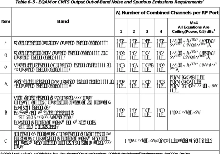
Table 6–5 lists the out-of-band spurious requirements. In cases where the N combined channels are not commanded to the same power level, “dBc” denotes decibels relative to the strongest carrier in the channel block. The out-of-band spurious emissions requirements assume a test condition with a contiguous block of N combined channels commanded to the same power level, and for this test condition "dBc" should be interpreted as the average channel power, averaged over the block, to mitigate the variation in channel power across the block (see Table 6–4), which is allowed with all channels commanded to the same power.
Items 1 through 4 list the requirements in channels adjacent to the commanded channels.
Item 5 lists the requirements in all other channels further from the commanded channels. Some of these “other” channels are allowed to be excluded from meeting the Item 5 specification. All the exclusions, such as 2nd and 3rd
harmonics of the commanded channel, are fully identified in the table.
Table 6–5 - EQAM or CMTS Output Out-of-Band Noise and Spurious Emissions Requirements7
N, Number of Combined Channels per RF Port
Item Band
1 2 3 4
N >4 All Equations Are Ceiling(Power, 0.5) dBc1 1 Adjacent channel up to 750 kHz from channel block edge <-58 dBc <-58 dBc <-58 dBc <-58 dBc <10*log10 [10-58/10 +(0.75/6)*
(10-65/10 + (
N-2)*10-73/10)]
2 Adjacent channel (750 kHz from channel block edge to 6 MHz from channel block edge) <-62 dBc <-60 dBc <-60 dBc <-60 dBc <10*log10 [10-62/10 +(5.25/6)*
(10-65/10 +(
N-2)*10-73/10)]
3 Next-adjacent channel (6 MHz from channel block edge to 12 MHz from channel block edge) <-65 dBc <-64 dBc <-63.5 dBc <-63 dBc <10*log10 [10-65/10 +(N-1)*10 -73/10]
4 Third-adjacent channel (12 MHz from channel block edge to 18 MHz from channel block edge). <-73 dBc <-70 dBc <-67 dBc <-65 dBc
For N=5: -64.5 dBc; For N=6: -64 dBc;
For N≥7: <-73 + 10*log10 (N)
dBc
5
Noise in other channels (47 MHz to 1000 MHz)
Measured in each 6 MHz channel excluding the following: a) Desired channel(s)
b) 1st, 2nd, and 3rd adjacent channels
(see Items 1, 2, 3, 4 in this table)
c) Channels coinciding with 2nd and 3rd harmonics
(see Item 6 in this table)
<-73 dBc <-70 dBc <-68 dBc <-67 dBc <-73 + 10*log10(N) 6
In each of 2N contiguous 6 MHz channels or in each of 3N contiguous 6 MHz channels coinciding with 2nd harmonic
and with 3rd harmonic components respectively (up to 1000
MHz)
< -73 + 10*log10(N), or -63 dBc, whichever is greater
Table Note 1. Use “Ceiling(2*Power) / 2” to get 0.5 steps from ceiling functions that return only integer values.
6.3.5.2 CMTS or EQAM Master Clock Jitter for Asynchronous Operation
An EQAM MUST implement a DTI client and client interface per the [DTI] specification. The Master Clock specifications are defined in the [DTI] specification. The DTI client provides the Master Clock. An integrated CMTS not actively serviced by a DTI server MUST include a Master Clock with the specifications as follows: The 10.24 MHz Master Clock MUST have, over a temperature range of 0 to 40 degrees C and for up to ten years from date of manufacture (see Note below):
• A frequency accuracy of <= ±5 ppm • A drift rate <=10-8per second, and
• An edge jitter of <=10 nSec peak-to-peak (±5 nSec)
Note: This specification MAY also be met by synchronizing the DRFI device Master Clock oscillator to an external
frequency reference source. If this approach is used, the internal DRFI device Master Clock MUST have a frequency accuracy of ±20ppm over a temperature range of 0 to 40 degrees C, up to 10 years from date of manufacture, when no frequency reference source is connected. The drift rate and edge jitter MUST be as specified above. 8
The drift rate and jitter requirements on the DRFI device Master Clock implies that the duration of two adjacent segments of 10,240,000 cycles will be within 30 nSec, due to 10 nSec jitter on each segments’ duration, and 10 nSec due to frequency drift. Durations of other counter lengths also may be deduced: adjacent 1,024,000 segments, <= 21 nSec; 1,024,000 length segments separated by one 10,240,000-cycle segment, <= 30 nSec; adjacent 102,400,000
7 Added footnote to Table 6-5 per ECN DRFI-N-06.0285-2 by GO on 10/9/06.
segments, <= 120 nSec. The DRFI device Master Clock MUST meet such test limits in 99% or more measurements.
6.3.5.3 CMTS or EQAM Master Clock Jitter for Synchronous Operation
In addition to the requirements in Section 6.3.5.2, the 10.24 MHz CMTS Master Clock MUST meet the following double sideband phase noise requirements over the specified frequency ranges:
• < [-50 + 20*log (fMC/10.24)] dBc (i.e., < 0.05 nSec RMS) 10 Hz to 100 Hz
• < [-58 + 20*log (fMC/10.24)] dBc (i.e., < 0.02 nSec RMS) 100 Hz to 1 kHz
• < [-50 + 20*log (fMC/10.24)] dBc (i.e., < 0.05 nSec RMS) 1 kHz to 10 kHz
• < [-50 + 20*log (fMC/10.24)] dBc (i.e., < 0.05 nSec RMS) 10 kHz to fMC/2
fMC is the frequency of the measured master clock in MHz. The value of fMC MUST be either an integral multiple or
divisor of 10.24 MHz. For example, if a 20.48 MHz oscillator is used as the master clock frequency source, and there is no explicit 10.24 MHz clock to test, the 20.48 MHz clock may be used with fMC equal to 20.48 in the above
expressions.
Specifications for EQAM Master Clock jitter in synchronous operation are contained in the [DTI] specification.
6.3.5.4 CMTS or EQAM Master Clock Frequency Drift for Synchronous Operation
The frequency of the CMTS Master Clock MUST NOT drift more than 10-8per second.
Specifications for EQAM Master Clock frequency drift in synchronous operation is contained in the DTI specification.
6.3.6 CMTS or EQAM Clock Generation
When the 10.24 MHz Master Clock is provided by the DTI interface, a DRFI-compliant device MUST lock the Downstream Symbol Clock to the 10.24 MHz Master Clock using the M/N divisors provided in Table 6–6.
6.3.6.1 CMTS Clock Generation
The CMTS MUST lock the Downstream Symbol Clock to the CMTS Master Clock using the M/N divisors provided in Table 6–6.
6.3.6.2 EQAM Clock Generation
Because it operates with an active DTI interface, an EQAM MUST lock the Downstream Symbol Clock to the Master Clock using the M/N divisors provided in Table 6–6.
6.3.6.3 Downstream Symbol Rate9
Let fb'represent the rate of the Downstream Symbol Clock which is locked to the Master Clock and let fm' represent
the rate of the Master Clock locked to the Downstream Symbol Clock. Let fbrepresent the nominal specified
downstream symbol rate and let fmrepresent the nominal Master Clock rate (10.24 MHz). With the Downstream
Symbol Clock locked to the Master Clock, the following equation MUST hold: fb’ = fm*M/N
With the Master Clock locked to the Downstream Symbol Clock, the following equation MUST hold: fm' = fb*N/M
Note that M and N in Table 6–6 are unsigned integer values, each representable in 16 bits and result in a value of fb'
or fm’ that is not more than ±1 ppm from its specified nominal value.
The standard deviation of the timing error of the EQAM/CMTS RF symbol clock, referenced to the DTI Server Master Clock, MUST be less than 1.5 ns measured over 100 seconds.
Table 6–6 - Downstream symbol rates & parameters for synchronization with Master Clock
Downstream mode Nominal Specified
Symbol Rate, fb (MHz) M/N Master Clock Rate, fm' (MHz) Downstream Symbol Rate, fb' (MHz) Offset from Nominal Annex B, 64QAM 5.056941 401/812 10.239990... 5.056945... 0.95 ppm Annex B, 256QAM 5.360537 78/149 10.240000... 5.360536... 0.02 ppm
6.3.7 Downstream Symbol Clock Jitter for Synchronous Operation
The downstream symbol clock MUST meet the following double sideband phase noise requirements over the specified frequency ranges:
• < [-53 + 20*log (fDS/5.057)] dBc (i.e., < 0.07 nSec RMS) 10 Hz to 100 Hz
• < [-53 + 20*log (fDS/5.057)] dBc (i.e., < 0.07 nSec RMS) 100 Hz to 1 kHz
• < [-53 + 20*log (fDS/5.057)] dBc (i.e., < 0.07 nSec RMS) 1 kHz to 10 kHz
• < [-36 + 20*log (fDS/5.057)] dBc (i.e., < 0.5 nSec RMS) 10 kHz to 100 kHz
• < [-30 + 20*log (fDS/5.057)] dBc (i.e., < 1 nSec RMS) 100 kHz to (fDS/2)
fDSis the frequency of the measured clock in MHz. The value of fDSMUST be an integral multiple or divisor of the
downstream symbol clock. For example, an fDS= 20.227764 MHz clock may be measured if there is no explicit
5.056941 MHz clock available.
A DRFI-compliant device MUST provide a means for clock testing in which:
• The device provides test points for direct access to the master clock and the downstream symbol clock. Alternatively, a DRFI conformant device MUST provide a test mode in which:
• The downstream QAM symbol sequence is replaced with an alternating binary sequence (1, -1, 1, -1, 1, -1...) at nominal amplitude, on both I and Q.
• The device generates the downstream symbol clock from the 10.24 MHz reference clock as in normal synchronous operation.
If an explicit downstream symbol clock, which is capable of meeting the above phase noise requirements, is available (e.g., a smooth clock without clock domain jitter), this test mode is not required.
6.3.8 Downstream Symbol Clock Drift for Synchronous Operation
The frequency of the downstream symbol clock MUST NOT drift more than 10-8 per second.
6.3.9 Timestamp Jitter10
The DOCSIS timestamp jitter MUST be less than 500 nsec peak-to-peak at the output of the Downstream Transmission Convergence Sublayer. This jitter is relative to an ideal Downstream Transmission Convergence Sublayer that transfers the MPEG packet data to the Downstream Physical Media Dependent Sublayer with a perfectly continuous and smooth clock at the MPEG packet data rate. Downstream Physical Media Dependent Sublayer processing MUST NOT be considered in timestamp generation and transfer to the Downstream Physical Media Dependent Sublayer.
Thus, any two timestamps N1 and N2 (N2 > N1) which were transferred to the Downstream Physical Media Dependent Sublayer at times T1 and T2 respectively must satisfy the following relationship:
| (N2-N1)/fCMTS - (T2-T1) | < 500x10-9
In the equation, the value of (N2-N1) is assumed to account for the effect of rollover of the timebase counter, and T1 and T2 represent time in seconds. fCMTS is the actual frequency of the CMTS master timebase and may include a
fixed frequency offset from the nominal frequency of 10.24 MHz. This frequency offset is bounded by a requirement further below in this section.
The jitter includes inaccuracy in timestamp value and the jitter in all clocks. The 500 nsec allocated for jitter at the Downstream Transmission Convergence Sublayer output MUST be reduced by any jitter that is introduced by the Downstream Physical Media Dependent Sublayer.
Note: Jitter is the error (i.e., measured) relative to the CMTS Master Clock. (The CMTS Master Clock is the 10.24 MHz clock used for generating the timestamps.)
7 DOWNSTREAM TRANSMISSION CONVERGENCE SUBLAYER
7.1 Introduction
The downstream transmission convergence layer used in the M-CMTS is defined as a continuous series of 188-byte MPEG [ISO 13818] packets. These packets consist of a 4-byte header followed by 184 bytes of payload. The header identifies the payload as belonging to the Data-Over-Cable MAC. Other values of the header may indicate other payloads. The mixture of MAC payloads and those of other services is optional and is controlled by the CMTS. Figure 7–1 illustrates the interleaving of DOCSIS MAC bytes with other digital information (digital video in the example shown).
header=DOC DOC MAC payload
header=video digital video payload
header=video digital video payload
header=DOC DOC MAC payload
header=video digital video payload
header=DOC DOC MAC payload
header=video digital video payload
header=video digital video payload
header=video digital video payload
Figure 7–1 - Example of Interleaving MPEG Packets in Downstream
7.2 MPEG Packet Format
The format of an MPEG Packet carrying DOCSIS data is shown in Figure 7–2. The packet consists of a 4-byte MPEG Header, a pointer_field (not present in all packets), and the DOCSIS Payload.
MPEG Header
(4 bytes) pointer_field (1 byte) (183 or 184 bytes) DOCSIS Payload Figure 7–2 - Format of an MPEG Packet
7.3 MPEG Header for DOCSIS Data-Over-Cable
The format of the MPEG Transport Stream header is defined in Section 2.4 of [ISO 13818]. The particular field values that distinguish Data-Over-Cable MAC streams are defined in Table 7–1. Field names are from the ITU specification.
The MPEG Header consists of 4 bytes that begin the 188-byte MPEG Packet. The format of the header for use on a DOCSIS Data-Over-Cable PID MUST be as shown in Table 7–1. The header format conforms to the MPEG standard, but its use is restricted in this specification to not allow inclusion of an adaptation_field in the MPEG packets.
Table 7–1 - MPEG Header Format for DOCSIS Data-Over-Cable Packets
Field Length (bits) Description
sync_byte 8 0x47; MPEG Packet Sync byte.
transport_error_indicator 1 Indicates that an error has occurred in the reception of the
packet. This bit is reset to zero by the sender, and set to one whenever an error occurs in the transmission of the packet.
payload_unit_start_indicator 1 A value of one indicates the presence of a pointer_field as
the first byte of the payload (fifth byte of the packet).
transport_priority 1 Reserved; set to zero.
PID 13 DOCSIS Data-Over-Cable well-known PID (0x1FFE).
transport_scrambling_control 2 Reserved, set to ‘00'.
adaptation_field_control 2 ‘01'; use of the adaptation_field is not allowed on the
DOCSIS PID.
continuity_counter 4 Cyclic counter within this PID.
7.4 MPEG Payload for DOCSIS Data-Over-Cable
The MPEG payload portion of the MPEG packet will carry the DOCSIS MAC frames. The first byte of the MPEG payload will be a ‘pointer_field' if the payload_unit_start_indicator (PUSI) of the MPEG header is set.
7.4.1 stuff_byte
This standard defines a stuff_byte pattern having a value (0xFF) that is used within the DOCSIS payload to fill any gaps between the DOCSIS MAC frames. This value is chosen as an unused value for the first byte of the DOCSIS MAC frame. The ‘FC' byte of the MAC Header will be defined to never contain this value. (FC_TYPE = ‘11' indicates a MAC-specific frame, and FC_PARM = ‘11111' is not currently used and, according to this specification, is defined as an illegal value for FC_PARM.)
7.4.2 pointer_field
The pointer_field is present as the fifth byte of the MPEG packet (first byte following the MPEG header) whenever the PUSI is set to one in the MPEG header. The interpretation of the pointer_field is as follows:
The pointer_field contains the number of bytes in this packet that immediately follow the pointer_field that the CM decoder will skip past before looking for the beginning of an DOCSIS MAC Frame. A pointer field MUST be present if it is possible to begin a Data-Over-Cable MAC Frame in the packet, and MUST point to either:
• the beginning of the first MAC frame to start in the packet, or • to any stuff_byte preceding the MAC frame.
7.5 Interaction with the MAC Sublayer
MAC frames may begin anywhere within an MPEG packet. MAC frames may span MPEG packets, and several MAC frames may exist within an MPEG packet.
The following figures show the format of the MPEG packets that carry DOCSIS MAC frames. In all cases, the PUSI flag indicates the presence of the pointer_field as the first byte of the MPEG payload.
Figure 7–3 shows a MAC frame that is positioned immediately after the pointer_field byte. In this case, the pointer_field is zero, and the DOCSIS decoder will begin searching for a valid FC byte, at the byte immediately following the pointer_field.
MPEG Header
(PUSI = 1) pointer_field (= 0) (up to 183 bytes) MAC Frame stuff_byte(s) (0 or more) Figure 7–3 - Packet Format where a MAC Frame Immediately Follows the Pointer Field
Figure 7–4 shows the more general case, where a MAC Frame is preceded by the tail of a previous MAC Frame and a sequence of stuffing bytes. In this case, the pointer_field still identifies the first byte after the tail of Frame #1 (a stuff_byte) as the position where the decoder should begin searching for a legal MAC sublayer FC value. This format allows the multiplexing operation in the CMTS to immediately insert a MAC frame that is available for transmission if that frame arrives after the MPEG header and pointer_field have been transmitted.
In order to facilitate multiplexing of the MPEG packet stream carrying DOCSIS data with other MPEG-encoded data, the CMTS SHOULD NOT transmit MPEG packets with the DOCSIS PID which contain only stuff_bytes in the payload area. MPEG null packets SHOULD be transmitted instead.
Note: There are timing relationships implicit in the DOCSIS MAC sublayer, which must also be preserved by
any MPEG multiplexing operation.
MPEG Header
(PUSI = 1) pointer_field (= M) Tail of MAC Frame #1 (M bytes) stuff_byte(s) (0 or more) Start of MAC Frame #2 Figure 7–4 - Packet Format with MAC Frame Preceded by Stuffing Bytes
Figure 7–5 shows that multiple MAC frames may be contained within the MPEG packet. The MAC frames may be concatenated one after the other or be separated by an optional sequence of stuffing bytes.
MPEG Header
(PUSI = 1) pointer_field (= 0) MAC Frame#1 MAC Frame #2 stuff_byte(s) (0 or more) MAC Frame #3 Figure 7–5 - Packet Format Showing Multiple MAC Frames in a Single Packet
Figure 7–6 shows the case where a MAC frame spans multiple MPEG packets. In this case, the pointer_field of the succeeding frame points to the byte following the last byte of the tail of the first frame.
MPEG Header
(PUSI = 1) pointer_field (= 0) stuff_byte(s) (0 or more) Start of MAC Frame #1 (up to 183 bytes) MPEG Header
(PUSI = 0) Continuation of MAC Frame #1 (184 bytes) MPEG Header
(PUSI = 1) pointer_field (= M) Tail of MAC Frame #1(M bytes) stuff_byte(s) (0 or more) Start of MAC Frame #2 (M bytes) Figure 7–6 - Packet Format where a MAC Frame Spans Multiple Packets
The Transmission Convergence sublayer must operate closely with the MAC sublayer in providing an accurate timestamp to be inserted into the Time Synchronization message.
7.6 Interaction with the Physical Layer
The MPEG-2 packet stream MUST be encoded according to [ITU-T J.83-B], including MPEG-2 transport framing using a parity checksum as described in [ITU-T J.83-B].