Dealer: This manual MUST be given to the end user.
User: BEFORE using this product, read this manual and save for future reference.
User Manual
For more information regarding Invacare products, parts, and services, please visit
www.invacare.com
Invacare XPO
2
™
Portable Concentrator
WARNING
WARNING
DO NOT USE THIS PRODUCT OR ANY
AVAILABLE OPTIONAL EQUIPMENT WITHOUT FIRST COMPLETELY READING AND
UNDERSTANDING THESE INSTRUCTIONS AND ANY ADDITIONAL INSTRUCTIONAL MATERIAL SUCH AS USER MANUALS, SERVICE MANUALS OR INSTRUCTION SHEETS SUPPLIED WITH THIS PRODUCT OR OPTIONAL EQUIPMENT. IF YOU ARE UNABLE TO UNDERSTAND THE WARNINGS, CAUTIONS OR INSTRUCTIONS, CONTACT A HEALTHCARE PROFESSIONAL, DEALER OR TECHNICAL PERSONNEL BEFORE ATTEMPTING TO USE THIS EQUIPMENT -
OTHERWISE, INJURY OR DAMAGE MAY OCCUR.
ACCESSORIES WARNING
INVACARE PRODUCTS ARE SPECIFICALLY DESIGNED AND MANUFACTURED FOR USE IN CONJUNCTION WITH INVACARE ACCESSORIES. ACCESSORIES DESIGNED BY OTHER
MANUFACTURERS HAVE NOT BEEN TESTED BY INVACARE AND ARE NOT RECOMMENDED FOR USE WITH INVACARE PRODUCTS.
NOTE: Updated versions of this manual can be found at www.invacare.com.
TABLE OF CONTENTS
TABLE OF CONTENTS
REGISTER YOUR PRODUCT ... 4
SPECIAL NOTES ... 5
Disposal of Equipment and Accessories ... 6
SECTION 1—GENERAL GUIDELINES ...7
Operating Information ... 8
Maintenance... 9
Radio Frequency Interference... 9
Polarized Plug Instruction...10
SECTION 2—PACKAGING AND HANDLING ...11
Unpacking...11
Inspection...11
Storage...11
SECTION 3—TECHNICAL DESCRIPTION ...12
SECTION 4—XPO2 FEATURES ...13
SECTION 5—TYPICAL PRODUCT PARAMETERS .14 Regulatory Listing...16
SECTION 6—OPERATING INSTRUCTIONS ...17
Introduction ...17
Filters ...17
Location...18
Recommendations for Optimal Performance...18
Power Supplies...19
Checking Charge Level of Internal Battery ...21
Charging the Batteries ...22
Battery Time Management...26
Prolonging XPO2 Battery Life...26
TABLE OF CONTENTS
TABLE OF CONTENTS
Connecting/Positioning the Nasal Cannula ...30
Adjusting the Pulse Flow Setting...31
Using the XPO2 Portable Concentrator...32
Indicators, Warnings and Alarms ...33
SECTION 7—CLEANING, CARE, AND MAINTENANCE ...37
Cabinet ...37
Air Intake Filter...38
Carrying Bag ...39
SECTION 8—TROUBLESHOOTING GUIDE ...40
SECTION 9—OPTIONAL ACCESSORIES ...45
SPECIAL NOTES
SPECIAL NOTES
Signal words are used in this manual and apply to hazards or unsafe practices which could result in personal injury or property damage. Refer to the following table for definitions of the signal words.
NOTICE
The information contained in this document is subject to change without notice.DANGER
DO NOT SMOKE while using this device. Keep all
matches, lit cigarettes, candles or other sources of ignition
out of the room in which this product is located and away
from where oxygen is being delivered.
NO SMOKING signs should be prominently displayed.
Textiles and other materials that normally would not burn
are easily ignited and burn with great intensity in oxygen
enriched air. Failure to observe this warning can result in
severe fire, property damage and cause physical injury or
death.
SIGNAL WORD MEANING
DANGER
Danger indicates an imminently hazardous situation which, if not avoided, will result in death or serious injury.
WARNING
Warning indicates a potentially hazardous situation which, if not avoided, could result in death or serious injury.
CAUTION
Caution indicates a potentially hazardous situation which, if not avoided, may result in property damage or minor injury or both.
SPECIAL NOTES
CAUTION
“Caution: Federal law restricts this device to sale or rental by or on order of a physician, or any other practitioner licensed by the law of the State in which he/she practices to use or order the use of this device.” Invacare recommends an alternate source of supplemental oxygen in the event of a power outage, alarm condition or mechanical failure. Consult your physician or equipment provider for the type of reserve system required. This equipment is to be used as an oxygen supplement and is not considered life supporting or life sustaining.Disposal of Equipment and Accessories
Follow local governing ordinances and recycling plans regarding disposal of device components. DO NOT dispose of the internal or supplemental battery packs. Battery packs should be returned to your dealer/provider.
SECTION 1—GENERAL GUIDELINES
SECTION 1—GENERAL GUIDELINES
In order to ensure the safe installation, assembly and operation of the XPO2 Portable Concentrator these instructions MUST be followed.
WARNING
This section contains important information for the safe operation and use of this product.DANGER
Risk of electric shock. DO NOT disassemble. Refer servicing
to qualified service personnel. No user serviceable parts. TO REDUCE THE RISK OF BURNS, ELECTROCUTION,
FIRE OR INJURY TO PERSONS
A spontaneous and violent ignition may occur if oil, grease,
greasy substances, or petroleum based products come in
contact with oxygen under pressure. These substances
MUST be kept away from the XPO2 portable concentrator,
tubing and connections, and all other oxygen equipment.
DO NOT use any lubricants unless recommended by
Invacare.
Avoid using while bathing. If continuous usage is required
by the physician’s prescription, the concentrator MUST be
located in another room at least seven feet from the bath. DO NOT come in contact with the concentrator while wet. DO NOT place or store product where it can drop into water
or other liquid.
DO NOT reach for product that has fallen into water.
SECTION 1—GENERAL GUIDELINES
DANGER
Keep the oxygen tubing, cord, and unit out from under such
items as blankets, bed coverings, chair cushions, clothing
and away from heated or hot surfaces, including space
heaters, stoves and similar electrical appliances.
Avoid creation of any spark near medical oxygen
equipment. This includes sparks from static electricity
created by any type of friction.
DO NOT move or relocate concentrator by pulling on the cord.
A product should NEVER be left unattended when plugged in. Make sure XPO2 is Off when not in use.
Outdoor use of the XPO2 MUST be conducted with internal or supplemental battery power only.
Operating Information
The XPO2 cannot be used in conjunction with PAP, Bi‐Level or other such devices. If the XPO2 is not working properly, if it has been dropped or damaged, or dropped into water, call equipment provider/qualified technician for examination and repair. If you feel ill or uncomfortable, or if the unit does not signal an oxygen pulse and you are unable to hear and/or feel the oxygen pulse, consult your equipment provider and/or your physician IMMEDIATELY. NEVER drop or insert any object or liquid into any opening. DO NOT use extension cords with AC power adapters provided.
SECTION 1—GENERAL GUIDELINES For optimum performance, Invacare recommends that each concentrator be on and running for a minimum of 5 minutes. Shorter periods of operation may reduce maximum product life.
The XPO2 is not designed to be used with a humidifier. Use of this device with a humidifier may impair performance and/or damage the equipment.
When your automobile is turned Off, disconnect the car accessory power supply and remove the XPO2 from the automobile. NEVER allow the XPO2 to be stored in a very hot or cold automobile or in other similar, high or low, temperature environments. Refer to Typical Product Parameters on page 14. DO NOT operate in temperatures below 41° F (5°C) or above 104° F (40° C) for extended periods of time. The XPO2 MUST be used in an upright position. Invacare recommends the XPO2 not be used in the rain.
Maintenance
The XPO2 was specifically designed to minimize routine preventive maintenance. Only professionals of the healthcare field or persons fully conversant with this process such as factory trained personnel should perform preventive maintenance or performance adjustments on the oxygen concentrator.Radio Frequency Interference
This equipment has been tested and found to comply with EMC limits specified by IEC/EN 60601‐1‐2. These limits are designed to provide a reasonable protection against
SECTION 1—GENERAL GUIDELINES
Other devices may experience interference from even the low levels of electromagnetic emissions permitted by the above standards. To determine if the emissions from the XPO2 are causing the interference, turn the XPO2 Off. If the interference with the other device(s) stops, then the XPO2 is causing the interference. In such rare cases, interference may be reduced or corrected by one of the following measures: • Reposition, relocate, or increase the separation between the equipment. • Connect the equipment into an outlet on a circuit different from that to which the other device(s) is connected. DO NOT connect the concentrator in parallel or series with other oxygen concentrators or oxygen therapy devices.
Close supervision is necessary when this product is used near children or physically‐challenged individuals. Additional monitoring or attention may be required for patients using this device who are unable to hear or see alarms or communicate discomfort. Be aware that electrical cords and/or tubing could present a tripping hazard. A change in altitude may affect total oxygen available to you. Consult your physician before traveling to higher or lower altitudes to determine if your flow settings should be changed.
Polarized Plug Instruction
As a safety feature, this appliance may have a polarized plug (one blade is wider than the other). This plug will fit in a polarized outlet only one way. If the plug does not fit fully in the outlet, reverse the plug. If it still does not fit, contact a qualified electrician. DO NOT attempt to defeat this safety feature.
SECTION 2—PACKAGING AND HANDLING
SECTION 2—PACKAGING AND
HANDLING
Unpacking
1. Check for any obvious damage to the carton or its contents. If damage is evident, notify the carrier, or your local dealer. 2. Remove all loose packing from the carton.3. Carefully remove all the components from the carton. The Invacare XPO2 Portable Oxygen Concentrator packaging contains the following items (as shown below). If any parts are missing, please contact your equipment provider. • XPO2 portable oxygen concentrator with carrying bag • Operator’s manual • AC power adapter • DC power adapter • Supplemental battery (Model XPO100B only) NOTE: Retain all containers and packing materials for storage or return shipment.
Inspection
Inspect/examine exterior of the oxygen concentrator and accessories for damage. Inspect all components.Storage
1. Store the repackaged oxygen concentrator in a dry area. 2. DO NOT place objects on top of packaged concentrator.SECTION 3—TECHNICAL DESCRIPTION
SECTION 3—TECHNICAL
DESCRIPTION
The Invacare portable concentrator is to be used by patients with respiratory disorders who require supplemental oxygen. The device is not intended to sustain or support life. The oxygen concentration level of the output gas ranges from 87% to 95.6%. The oxygen is delivered to the patient through the use of a nasal cannula. When the demand for oxygen is detected, the oxygen is delivered through pulsed flow with pulse flow settings of 1 through 5.
The Invacare portable concentrator uses a molecular sieve and pressure swing adsorption methodology to produce the oxygen gas output. Ambient air enters the device, is filtered and then compressed. This compressed air is then directed toward one of two nitrogen adsorbing sieve beds.
Concentrated oxygen exits the opposite end of the active sieve bed and is directed into an oxygen reservoir where it is delivered to the patient in specific volumes during the inhalation portion of a detected breath. The Invacare portable concentrator is capable of operation by the patient in a home environment, in an institutional environment or in a vehicle or other mobile environment. Device standard power options include an AC to DC
switching power supply operating from AC power outlet (120 VAC/ 60 Hertz or 230VAC/50 Hertz nominal), a DC to DC switching power supply operating from accessory outlets typically found in a mobile vehicle type environment (12 VDC nominal) and a supplemental rechargeable battery.
SECTION 4—XPO2 FEATURES
SECTION 4—XPO
2FEATURES
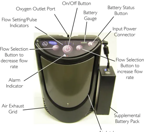
Please review the figures below to familiarize yourself with the locations of the XPO2 features and controls.
FIGURE 4.1 XPO2 Features
Alarm Indicator Flow Selection Button to decrease flow rate Flow Setting/Pulse Indicators
Oxygen Outlet Port
Air Exhaust Grid Input Power Connector Battery Status Button Flow Selection Button to increase flow rate Battery Gauge On/Off Button Air Intake Supplemental Battery Pack
SECTION 5—TYPICAL PRODUCT PARAMETERS
SECTION 5—TYPICAL PRODUCT
PARAMETERS
Direct Current Type BF equipment
Attention - Consider Accompanying Documents DO NOT smoke
Class II, Double Insulation Power On/Off
DO NOT dispose of in household waste
Recycle
DO NOT use oil or grease Keep dry
IPX1 Protected against dripping water
Electrical Requirements: AC Power Supply: 100-240 VAC 50/60 Hertz
DC Power Supply: 11-16 VDC Rated Current Input: 1.0 amps at 120 VAC
3.3 amps at 18 VDC Sound Level @ setting 2: < 45dBA weighted
SECTION 5—TYPICAL PRODUCT PARAMETERS Oxygen Concentration:*
*Based on an atmospheric pressure of 14.7 psi (101 kPa) at 70°F (21°C)
87% to 95.6%, after initial warm-up period (approximately 5 minutes)
Oxygen Flow: Pulse flow delivery. Bolus Volume Ranges From 300 - 840cc settings 1 to 5.
Dimensions: 10” high x 7” wide x 4” deep (25.4 cm high x 17.8 cm wide x 10.2 cm wide) Weight: 6.0 lbs (2.72 kg); 1.3 lbs (0.68 kg) for
supplemental battery Battery Duration (times are
approximate): Setting 1 = 3.5 hrsSetting 2 = 2.5 hrs Setting 3 = 2.0 hrs Setting 4 = 1.5 hrs Setting 5 = 1.0 hrs Battery Recharge Time:
NOTE: Recharge time increases if battery is charging while unit is running.
4 hours
Humidity Operating Humidity: 15% to 60% non condensing
Storage Humidity: up to 95% non condensing
Temperature Range:
(All power sources) Operating temperature: 41°F to 95°F (5°C to 35°C) Storage temperature: -2°F to 140°F (-20°C to 60°C)
Extended Temperature Range:
(Using AC or DC adapters) Operating Temperature: 95°F to 104° (35°C to 40°C) Continuous use - all settings Extended Temperature Range
(Using Internal Battery) Operating Temperature: 95°F to 104° (35°C to 40°C) Continuous use - settings 1, 2 and 3 45 minutes (max) - setting 4 30 minutes (max) - setting 5
SECTION 5—TYPICAL PRODUCT PARAMETERS
Regulatory Listing
ETL certified complying with: EN 55011:1998 CISPR 11: 2003 IEC 60601-1; 2nd ed. 2005 IEC 60601-1-2; 2.1 ed. IEC 61000-3-2:2005 IEC 61000-3-3:2005 UL 60601-1, 1st ed. CSA 601.1 M90
SECTION 6—OPERATING INSTRUCTIONS
SECTION 6—OPERATING
INSTRUCTIONS
Introduction
Oxygen concentrators were introduced in the mid‐1970’s to provide supplemental oxygen to those in need. Oxygen concentrators separate nitrogen from air to create a high concentration oxygen gas output. Until now, the size and weight of traditional oxygen concentrator’s have limited their portability. The XPO2 delivers a pulse flow of oxygen in a lightweight package that can be easily carried and used away from home. This operator’s manual will acquaint you with the XPO2 and its accessories. Please make sure you read and understand all the information contained in this manual before you operate your unit. Should you have any questions, please contact your equipment provider.Filters
Air enters the XPO2 through an air intake filter located under the cover on the front of the unit. This filter prevents hair and other large particles in the air from entering the unit. Before you operate the XPO2, make sure this filter is clean, dry and properly positioned. To clean/replace the air intake filter, refer to Cleaning, Care, And Maintenance on page 37.SECTION 6—OPERATING INSTRUCTIONS
Location
WARNING
NEVER block the air openings of the product or place it on a soft surface, such as a bed or couch, where the air opening may be blocked. Keep the openings free from lint, hair and the like.
Keep unit at least three inches away from walls, draperies, furniture, and the like.
Locate and position the XPO2 in a well ventilated space so that the air intake and the air exhausts are not obstructed.
Recommendations for Optimal
Performance
Operating Temperature: 41°F to 95°F (5°C to 35°C) Relative Humidity: 15% to 60%
Transport/Storage
Temperature: -2°F to 140°F (-20°C to 60°C)Allow unit to warm, or cool, to operating temperature range before using.
Electrical: No extension cords.
Altitude: Up to 10,000 ft (3046 m) above sea level. Tubing and Cannula: 4 ft cannula with a maximum 25 ft of crush
resistant tubing (DO NOT pinch). Environment: Smoke, pollutant and fume free. No
confined spaces (example: no closets). Time of Operation: Up to 24 hours per day when connected to
SECTION 6—OPERATING INSTRUCTIONS
Power Supplies
WARNING
Use only Invacare specified power supplies with the XPO2 portable concentrator. Use of other non approved power supplies with the XPO2 can cause damage and/or injury and will void the warranty. NOTE: For this procedure, refer to FIGURE 6.1. The XPO2 can be supplied power from a factory installed internal battery, from an AC power adapter connected to the wall outlet, from a DC power adapter connected to a DC outlet like that found in an automobile, or from a supplemental battery pack.Internal Battery: A factory installed, rechargeable, internal battery is located inside the XPO2. When fully charged, it supplies power for up to 3.5 hours. An audible alarm sounds when the battery power is getting low. Refer to Indicators, Warnings and Alarms on page 33.
AC Power Adapter: An AC power adapter allows the XPO2 to be connected to a 100‐240 volt 50/60 hertz outlet. The power adapter converts AC voltage to a DC voltage that can be used to power the XPO2. Use of the AC power adapter will allow the XPO2 to be operated and simultaneously recharge the internal battery. This AC power adapter can also be used to recharge the supplemental battery pack. Refer to Charging the Batteries on page 22.
SECTION 6—OPERATING INSTRUCTIONS
DC Power Adapter: A DC power adapter allows the XPO2 to be connected to an automobile’s (boat, motor home, etc.…) 12‐volt DC outlet. Use of the DC power adapter will allow the XPO2 to be operated and simultaneously recharge the internal battery. This DC power adapter can also be used to recharge the supplemental battery pack. Refer to Charging the
Batteries on page 22.
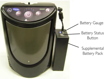
Supplemental Battery Pack: The XPO2 can be powered by a supplemental battery pack. This battery pack can be attached to the XPO2 carrying bag and connected to the power input connector of the unit. The supplemental battery pack will provide up to 3.5 hours of additional run time. The supplemental battery pack has its own battery status button and battery gauge to identify the level of battery charge. NOTE: The supplemental battery cannot be used to charge the internal battery.
FIGURE 6.1 Power Supplies
Supplemental Battery Pack Battery Status
Button Battery Gauge
SECTION 6—OPERATING INSTRUCTIONS
Checking Charge Level of Internal
Battery
NOTE: For this procedure, refer to FIGURE 6.2.
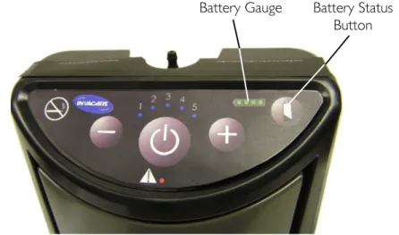
NOTE: Perform this procedure after charging the batteries and prior to using the XPO2 for the first time and prior to any subsequent use to ensure the internal battery is fully charged. 1. Turn On the XPO2 by pressing and holding the On/Off button. 2. Press and hold the battery status button located on the keypad. NOTE: Pressing the battery status button will illuminate the battery gauge and indicate the charge level of the internal battery. When the battery is fully charged all four battery gauge indicator lights will illuminate and stay illuminated until the button is released. Lesser charges will illuminate fewer gauge indicator lights.
FIGURE 6.2 Checking Charge Level of Internal Battery
Battery Status Button Battery Gauge
SECTION 6—OPERATING INSTRUCTIONS
Charging the Batteries
Charging the Internal Battery
NOTE: For this procedure, refer to FIGURE 6.3.
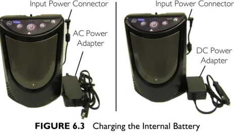
1. To charge the internal battery, do one of the following: • Connect the AC power adapter (if charging from a wall
outlet) to the input power connector located on the side of the unit and then plug the other end of the power adapter into the power source. • Connect the DC power adapter (if charging from a vehicle) to the input power connector located on the side of the unit and then plug the other end of the power adapter into the power source. NOTE: If internal battery is completely discharged, it will fully charge in approximately 3 to 4 hours. The battery gauge will illuminate during charging. It is recommended to recharge the internal battery, even if only partially depleted, as often as possible.
FIGURE 6.3 Charging the Internal Battery
AC Power Adapter
DC Power Adapter
SECTION 6—OPERATING INSTRUCTIONS
Charging the Supplemental Battery Only
NOTE: For this procedure, refer to FIGURE 6.4 on page 24. 1. Connect the AC (Detail “A”) or DC (Detail “B”) power
adapter to the supplemental battery pack.
2. Connect the other end of the AC (Detail “A”) or DC (Detail “B”) power adapter into the appropriate power source. NOTE: If completely discharged, the supplemental battery will fully charge in approximately 3 to 4 hours. Supplemental Battery Gauge indicator lights DO NOT illuminate during charging.
Supplemental Battery Status Button
NOTE: For this procedure, refer to Detail “C” in FIGURE 6.4 on page 24.
NOTE: Pressing the battery status button while charging turns the battery gauge On and shows the status of the battery capacity. The battery gauge also flashes “the last” or highest light bar to show that the battery pack is charging. The flashing bar shows the battery is actually being charged. The lit bars show the status of the battery capacity being restored.
SECTION 6—OPERATING INSTRUCTIONS
FIGURE 6.4 Charging the Supplemental Battery Only
DC Power Adapter Supplemental Battery Pack
AC Power Adapter DETAIL “A” - USING AC POWER ADAPTER DETAIL “B” - USING DC POWER ADAPTER Battery Gauge
Supplemental Battery Pack
Battery Status Button
DETAIL “C”
Supplemental Battery Pack
SECTION 6—OPERATING INSTRUCTIONS
Charging the Internal and Supplemental Battery
Pack Simultaneously
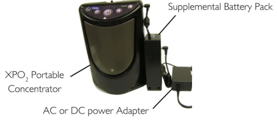
NOTE: For this procedure, refer to FIGURE 6.5. 1. To charge the supplemental battery pack and internal battery together, perform the following: A. Connect the AC or DC power adapter to the supplemental battery pack as shown. B. Connect the supplemental battery pack to the XPO2 as shown. C. Plug the other end of the adapter into the power source. NOTE: The internal battery gauge will illuminate during charging. Supplemental battery gauge indicator lights DO NOT illuminate during charging. NOTE: You may operate your XPO2 Portable Concentrator while the internal and/or the supplemental battery is being charged. Use of the XPO2 during charging will lengthen the amount of time required to reach full charge status of the batteries.FIGURE 6.5 Charging the Internal and Supplemental Battery
Pack Simultaneously
XPO2 Portable
Concentrator
AC or DC power Adapter
SECTION 6—OPERATING INSTRUCTIONS
Battery Time Management
Time away from home is almost limitless by combining the use of the AC power supply, DC power supply and the XPO2 batteries. To ensure the batteries maintain their optimal charge level, utilize the AC power supply whenever you have access to electric power. Utilize the DC power supply
whenever you are in a vehicle.
Prolonging XPO
2Battery Life
NOTE: For this procedure, refer to FIGURE 6.6.
Do’s
• When you first receive your XPO2, fully charge the internal battery (and supplemental external battery if provided) overnight. • Keep your batteries fully charged when using the XPO2 regularly. • Your XPO2 and supplemental external battery can be recharged at any time. These batteries can have their charge “topped off” at any time. • Always ensure the XPO2 internal and supplemental external batteries are recharged as soon as possible after they become fully discharged. The batteries may be permanently degraded if left fully discharged for an extended length of time. • Check the status of your XPO2 internal and supplemental external battery once a month if you are not using your XPO2 regularly. Both batteries should be maintained at 2 illuminated bars worth of charge. • Heat is the worst enemy of a battery. Allow plenty of air to circulate around the XPO2 so that the battery is kept as cool as possible when charging and also when in use.SECTION 6—OPERATING INSTRUCTIONS
Don’ts
• DO NOT use or leave the XPO2 or supplemental external battery in excessive heat or cold. • DO NOT store or leave the XPO2 or supplemental external battery in car trunks, etc. for extended periods of time. • DO NOT store either battery fully charged (4 bars illuminated on the unit’s battery gauge) if you are going to store your XPO2 for any time greater than 2 weeks. Recharge or discharge the battery to 2 bars (50% charge) only. Storing a battery with a full charge may degrade its useful life. • DO NOT leave your supplemental external battery plugged into the XPO2 when the XPO2 is not in use. The supplemental external battery will lose charge while plugged into the XPO2 even with the XPO2 turned off.FIGURE 6.6 Prolonging XPO2 Battery Life
Battery Gauge
Battery Status Button
Supplemental Battery Pack
SECTION 6—OPERATING INSTRUCTIONS
Powering the XPO
2NOTE: Both the internal and supplemental battery require full charging prior to first use. Refer to Charging the Batteries on page 22.
NOTE: For this procedure, refer to FIGURE 6.7 on page 29.
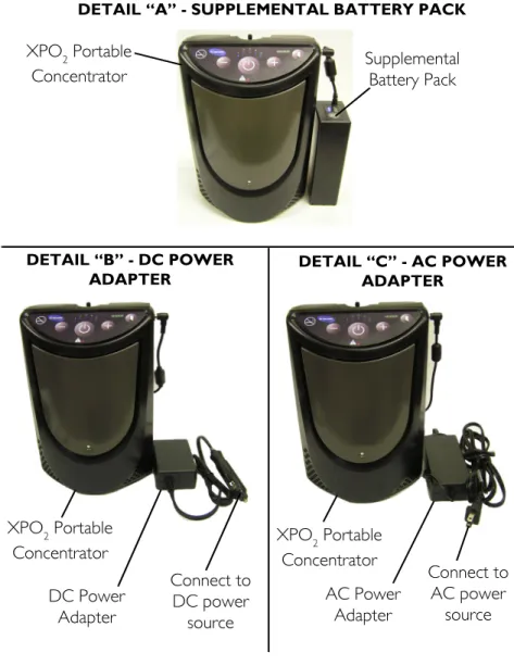
1. The XPO2 allows the freedom to choose from the following power sources: • The internal battery. The XPO2 comes equipped with an internal battery that is installed at the factory and is not user serviceable. • The supplemental battery pack. To use, connect the supplemental battery pack to the XPO2 as shown in Detail “A”.
• A DC power outlet (i.e. an automobile). To use, connect the DC power adapter to the XPO2 as shown in Detail “B”. Connect the other end of the DC power adapter to the DC power source.
• An AC outlet (i.e. wall outlet of your home). To use, connect the AC power adapter to the XPO2 as shown in Detail “C”. Connect the other end of the AC power adapter to the AC power outlet. 2. If the XPO2 is in use and connection to an external power supply is necessary, perform the following: A. Turn off the XPO2. B. Connect the external power supply (e.g. supplemental battery pack, DC mobile power adapter, or AC power adapter) to the XPO2. C. Turn the XPO2 on.
SECTION 6—OPERATING INSTRUCTIONS
FIGURE 6.7 Powering the XPO2
DETAIL “A” - SUPPLEMENTAL BATTERY PACK
DETAIL “B” - DC POWER
ADAPTER DETAIL “C” - AC POWER ADAPTER
XPO2 Portable
Concentrator Supplemental Battery Pack
XPO2 Portable Concentrator DC Power Adapter Connect to DC power source XPO2 Portable Concentrator AC Power Adapter Connect to AC power source
SECTION 6—OPERATING INSTRUCTIONS
Connecting/Positioning the Nasal
Cannula
CAUTION
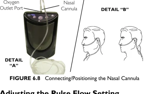
To ensure proper breath detection and oxygen delivery, DO NOT use tubing length exceeding 25 ft (7.6 m). NOTE: For this procedure, refer to FIGURE 6.8. NOTE: Invacare recommends using the XPO2 with a 4 ft (1.2 m) cannula. The tubing must be connected to the XPO2 oxygen outlet as shown below. NOTE: Replace the nasal cannula on a regular basis. Check with your equipment provider or physician to determine how often the cannula should be replaced. NOTE: DO NOT share cannulas between patients. 1. Connect the nasal cannula to the XPO2 oxygen outlet port (Detail “A”). 2. Place the cannula over your ears and position the prongs in your nose as instructed by your health care provider or cannula manufacturer (Detail “B”).SECTION 6—OPERATING INSTRUCTIONS
FIGURE 6.8 Connecting/Positioning the Nasal Cannula
Adjusting the Pulse Flow Setting
CAUTION
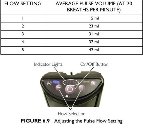
It is very important to select the prescribed level of oxygen flow. DO NOT increase or decrease the flow unless a change has been prescribed by your physician or therapist. NOTE: For this procedure, refer to FIGURE 6.9 on page 32. 1. Turn On the XPO2 by pressing and holding the power On/Off button for approximately one second. Each time the XPO2 is turned On, a brief alarm will sound. The XPO2 pulse flow setting at power‐up will be the same flow setting selected the last time the unit was turned Off. 2. The XPO2 has five pulse flow settings. Press the flow selection (+ or ‐) button until your prescribed flow setting (1 to 5) is illuminated by a blue indicator light. Nasal Cannula Oxygen Outlet Port DETAIL “A” DETAIL “B”SECTION 6—OPERATING INSTRUCTIONS
FIGURE 6.9 Adjusting the Pulse Flow Setting
Using the XPO
2Portable Concentrator
1. Turn the XPO2 On by pressing the On/Off button. 2. Breathe normally through your nose. Breathing through your mouth may result in less effective oxygen therapy. The XPO2 will put out a measured pulse of oxygen each time it detects inhalation. The blue flow setting indicator light will blink each time an inhalation is detected and the XPO2 outputs a pulse of oxygen. 3. Turn the XPO2 Off by pressing and holding the power On/Off button for approximately two seconds. NOTE: The time required for the XPO to reach maximum oxygen
FLOW SETTING AVERAGE PULSE VOLUME (AT 20 BREATHS PER MINUTE)
1 15 ml 2 23 ml 3 31 ml 4 37 ml 5 42 ml On/Off Button Flow Selection Indicator Lights
SECTION 6—OPERATING INSTRUCTIONS
Indicators, Warnings and Alarms
Start‐Up Indicator – The XPO2 will turn On all lights briefly and check for stuck buttons upon power up. It will then output a brief audible beep when first turned On to indicate the unit is operational. Breath Detect Indicator ‐ The XPO2 will put out a measured pulse of oxygen each time it detects an inhalation. The blue flow setting indicator light will blink each time an inhalation is detected and the XPO2 outputs a pulse of oxygen. Internal Battery Charging Indicator – When the unit is not turned On, but the AC, or DC, charger is connected to the unit and providing power, the Battery Gauge Display will
sequentially illuminate each of the four segments. Periodically the sequential illumination will be interrupted by the actual battery charge display. If the unit is fully charged, all four segments will be illuminated continuously until the unit is turned On, or removed from charger power. If no Battery Gauge Display segments are illuminated, the unit is not charging. The lack of charging could be due to either a loss of power, loose charger connections or the internal battery is not at the proper temperature for charging. Allow the unit to warm, or cool, to recommended charging temperature range (see Recommendations for Optimal Performance on page 18), check for loose connections and/or try a different power outlet. Low Battery Warning – When the XPO2 internal battery (or supplemental battery, if applicable) capacity drops to 25%, a brief audible beep will sound. The green 25% battery gauge indicator will intermittently blink. Low Battery Alarm – When the XPO2 internal battery (or supplemental battery, if applicable) capacity drops to 15%, a double audible beep will sound. The green 25% battery gauge indicator will rapidly blink.
SECTION 6—OPERATING INSTRUCTIONS Battery Discharged Alarm – Once the XPO2 internal battery (or supplemental battery, if applicable) capacity drops to minimum, a triple audible beep will sound and the GREEN 25% battery gauge indicator will blink very rapidly. The unit will then shutdown. No Breath Detect Alarm ‐ When the XPO2 is operating but does not sense breathing, a constant audible alarm sounds and the red alarm indicator light will illuminate continuously. If this occurs, check the connection from the cannula to the XPO2 unit and ensure that you are breathing through your nose. If the alarm continues, change to an alternate source of oxygen and contact your equipment provider. Breath Rate Over Capacity Alarm – If your breathing rate causes the capacity of the XPO2 to be exceeded, an intermittent audible beep sounds and the red alarm indicator will illuminate intermittently. When this occurs, reduce your activity and/or change to another source of oxygen. If your breathing rate continues to increase the audible beeps and red indicator blinks will become more rapid. NOTE: Oxygen will be supplied during this alarm. System Too Hot/Cold for Start Alarm – If the internal sensors register temperatures outside factory set levels upon start‐up, the unit will alarm with a rapid audible beep, the red alarm indicator light will illuminate continuously, the unit will not operate and the flow setting 1 & 2 blue indicator lights will illuminate. The fan will turn On. Allow the unit to cool or warm to the recommended operating temperature range (see Recommendations for Optimal Performance on page 18). Turn Off the unit and try again. Change to an alternate source of oxygen while waiting. If the alarm continues, contact your equipment provider.
SECTION 6—OPERATING INSTRUCTIONS System Too Hot/Cold Running Alarm – If the internal sensors register temperatures outside factory set levels during
operation, the unit will alarm with a rapid audible beep, the red alarm indicator light will illuminate continuously, the unit will not operate and the flow setting 1 & 3 blue indicator lights will illuminate. The fan will turn On. Allow the unit to cool or warm to the recommended operating temperature range (see Recommendations for Optimal Performance on page 18). Turn Off the unit and try again. Change to an alternate source of oxygen while waiting. If the alarm continues, contact your equipment provider. Battery Too Hot/Cold Alarm – If the internal battery sensor registers temperature outside a factory defined temperature range while the unit is operating, the unit will alarm with a rapid audible beep, the red alarm indicator light will illuminate continuously, the unit will stop running and the flow setting 1 & 4 blue indicator lights will illuminate. Turn Off the unit and disconnect AC or DC power adapters. Allow to the unit to cool or warm, to the recommended operating temperature range (see Recommendations for Optimal Performance on page 18) and try again. Change to an alternate source of oxygen while waiting. If the alarm continues, contact your equipment provider.
Stuck Button Alarm – During power up of the unit, if it detects that a button is stuck or being pressed too early, the unit will alarm with a rapid audible beep, the red alarm indicator light will illuminate continuously, the unit will not operate and the flow setting 1 & 5 blue indicator lights will illuminate. Turn Off the unit. Individually press all the front panel buttons, looking for buttons that seem stuck in a “pressed” position. Try turning On the unit again without pressing any other buttons during the power up. If the alarm continues, change to an alternate source of oxygen and contact your equipment provider.
SECTION 6—OPERATING INSTRUCTIONS
Operating Alarm – If unit detects abnormal operating
conditions in the unit, the unit will alarm with a rapid audible beep, the red alarm indicator light will illuminate
continuously, the unit will not operate and the flow setting 3
& 4 blue indicator lights will illuminate. Turn Off and then turn On the unit. If the alarm continues, you should change to another source of oxygen and contact your equipment
provider.
Compressor Alarm – If unit detects abnormal compressor conditions, the unit will alarm with a rapid audible beep, the red alarm indicator light will illuminate continuously, the unit will not operate and the flow setting 4 & 5 blue indicator lights will illuminate. Turn Off and then turn On the unit. If the alarm continues, you should change to another source of oxygen and contact your equipment provider. System Alarm – If unit detects abnormal system conditions, the unit will alarm with a rapid audible beep, the red alarm indicator light will illuminate continuously, the unit will not operate and the flow setting 3, 4 & 5 blue indicator lights will illuminate. Turn Off and then turn On the unit. If the alarm continues, you should change to another source of oxygen and contact your equipment provider. Audible Alarms ‐ To temporarily silence the audible alarms, quickly press the On/Off button. Except for the system Too Hot/Too Cold alarms, this feature will reset itself, every 30 seconds, each time a new alarm is triggered, or if the unit is turned Off. When performed during the system Too Hot/Too Cold alarms, the audible alarm will be silenced until a new alarm is triggered, or the unit is turned Off.
SECTION 7—CLEANING, CARE, AND MAINTENANCE
SECTION 7—CLEANING, CARE,
AND MAINTENANCE
WARNING
Turn Off the XPO2 and unplug the power cord before cleaning. DO NOT allow any cleaning agent to drip inside the air inlet and outlet openings. DO NOT spray or apply any cleaning agent directly to the cabinet.CAUTION
DO NOT clean the cabinet, carry bag, or filter with alcohol and alcohol based products (isopropyl alcohol), concentrated chlorine‐based products (ethylene chloride), and oil‐based products (Pine‐Sol®, Lestoil®) or any other harsh chemical agents. Only use mild liquid dish detergent (such as Dawn™).Cabinet
Periodically clean the XPO2 cabinet as follows: 1. Remove the XPO2 from the carrying bag. 2. Use a damp cloth, or sponge, with a mild detergent such as Dawn dish washing soap to gently clean the exterior case. 3. Allow the unit to air dry, or use a dry towel, before returning the unit to the carry bag or, operating the unit. 4. Return the XPO2 to its carry bag.SECTION 7—CLEANING, CARE, AND MAINTENANCE
Air Intake Filter
CAUTION
DO NOT operate the XPO2 without the air intake filter installed. NOTE: For this procedure, refer to FIGURE 7.1. NOTE: Remove the air intake filter and clean it at least once each week.1. Lift filter cover slightly and pull down to remove tabs from the grooves. 2. Lift out the filter. 3. Use a vacuum cleaner or wash with a mild liquid dish detergent (such as Dawn™) and water. Rinse thoroughly. 4. Thoroughly dry the filter and inspect for fraying, crumbling, tears and holes. Replace filter if any is found. 5. Reinstall the filter cover by placing the tabs in the slots and
engaging the magnet.
NOTE: Use only Invacare part number 1148281 as the air intake
filter for your XPO2.
FIGURE 7.1 Air Intake Filter
Cover
Filter
Magnet Cover Tabs
Magnet Grooves
SECTION 7—CLEANING, CARE, AND MAINTENANCE
Carrying Bag
NOTE: For this procedure, refer to FIGURE 7.2.CAUTION
DO NOT machine wash or dry the bag. 1. Remove the XPO2 from the bag 2. Wipe or brush the carry bag with a mild liquid dish detergent (such as Dawn™) and water. Rinse thoroughly. 3. Allow the bag to air dry after cleaning and before using. NOTE: Use only Invacare carrying bag, model XPO150.FIGURE 7.2 Carrying Bag
Shoulder Strap Carry Bag
XPO2 Portable
SECTION 8—TROUBLESHOOTING GUIDE
SECTION 8—TROUBLESHOOTING
GUIDE
If your XPO2 Portable Oxygen Concentrator fails to operate
properly, refer to the following chart for possible causes and solutions. If necessary, contact your service provider.
ALARM/WARNING:
SYMPTOM PROBABLE CAUSE SOLUTION
START-UP INDICATOR
XPO2 does not operate when On/Off button pressed. OR
Front panel lights DO NOT illuminate upon start-up OR
All front panel lights go dark.
On/Off button was not held
down long enough. Try to power up the unit again while continuing to press the On/Off button until the front panel lights begin to illuminate. This takes typically 2-3 seconds. Internal battery is
discharged (and supplemental battery if connected to the unit).
Connect XPO2 to either the AC or DC charger and retry.
Malfunction Change to an alternate oxygen supply and contact your equipment provider.
NO BREATH DETECTED ALARM:
Continuous audible beep and red alarm indicator is on continuously (not blinking) upon start up.
XPO2 has not detected a breath for a predetermined time period.
1. Verify the cannula is connected, not kinked, properly positioned and you are breathing through your nose. 2. If the alarm continues, change to another source of oxygen and contact your equipment provider.
SECTION 8—TROUBLESHOOTING GUIDE
CHARGING INDICATOR
With the unit turned Off and with the AC or DC charging adapter plugged into the unit, no Battery Gauge segments are illuminated. Battery Gauge is dark.
Power source is no good, or
there is a loose connection. Try another power outlet and check connections to charger and unit.
Internal Battery is outside the allowed temperature range for charging.
Allow unit to cool down to less than 95ºF, or warm up to 50ºF.
LOW BATTERY WARNING:
There is a single audible beep and the green 25% battery indicator is blinking.
Internal battery requires
charging. Connect XPOor DC power adapter, 2 to its AC or to its supplemental battery pack.
LOW BATTERY ALARM:
There is a double audible beep and the green 25% battery indicator is rapidly blinking.
Internal battery requires
charging. 1. Connect XPOAC or DC power 2 to its adapter, or to its supplemental battery pack. 2. If no other power source is available, change to a reserve oxygen supply.
BATTERY DISCHARGED ALARM:
There is a triple audible beep and the green 25% battery indicator is blinking very rapidly.
Internal battery is
completely discharged and needs to be recharged.
1. Connect XPO2 to its AC or DC power adapter, or to its supplemental battery pack. 2. If no other power source is available, change to a reserve oxygen supply. ALARM/WARNING:
SECTION 8—TROUBLESHOOTING GUIDE
BREATH RATE OVER CAPACITY ALARM:
Intermittent audible beep and illuminated red alarm indicator. Audible beeps and red indicator blinks become more rapid as breathing rate increases.
Your breathing rate has exceeded the capacity of the XPO2.
1. Immediately reduce your activity level to get your breath rate to slow down, and / or
2. If the alarm continues, change to another source of oxygen.
SYSTEM TOO HOT/COLD TO START ALARM:
Continuous audible beep and red alarm indicator is illuminated. Fan is On. AND Flow indicators 1 & 2 are illuminated.
Unit is too hot, or too cold,
to allow it to turn On. 1. Allow unit to cool down to less than 95ºF, or warm up to 50ºF, before turning the unit Off, then On again. 2. If the alarm continues, change to another source of oxygen and contact your equipment provider
SYSTEM RUNNING TOO HOT/COLD ALARM:
Continuous audible beep and red alarm indicator is illuminated. Fan is On. AND Flow indicators 1 & 3 are illuminated.
Unit has become too hot, or
too cold, during operation. 1. Allow unit to cool down to less than 95ºF, or warm up to 50ºF, before turning the unit On again
2. If the alarm continues, change to another source of oxygen and contact your equipment provider
ALARM/WARNING:
SECTION 8—TROUBLESHOOTING GUIDE
BATTERY TOO HOT/COLD ALARM:
Continuous audible beep and red alarm indicator is illuminated. AND Flow indicators 1 & 4 are illuminated.
Internal Battery has become too hot, or too cold, during operation.
1. Unplug chargers if connected.
2. Allow unit to cool down to less than 95ºF, or warm up to 50ºF, before resuming charging or turning Off the unit and turning the unit On again.
3. If the alarm continues, change to another source of oxygen and contact your equipment provider.
STUCK BUTTON ALARM:
Continuous audible beep and red alarm indicator is illuminated. AND Flow indicators 1 & 5 are illuminated.
A stuck button is being
detected upon power up. 1. Turn Off the unit2. With the unit turned Off, press each control button looking for a stuck button 3. Turn On the unit while ensuring that you are not continuing to hold the Power On/Off button once the lights begin to illuminate. 4. If the alarm continues, change to another source of oxygen and contact your equipment provider
ALARM/WARNING:
SECTION 8—TROUBLESHOOTING GUIDE
OPERATING ALARM:
Continuous audible beep and red alarm indicator is illuminated. AND Flow indicators 3 & 4 are illuminated.
Abnormal operation has
been detected. 1. Turn Off the unit. 2. Turn On the unit. 3. If the alarm continues, change to another source of oxygen and contact your equipment provider
COMPRESSOR ALARM:
Continuous audible beep and red alarm indicator is illuminated. AND Flow indicators 4 & 5 are illuminated. Abnormal compressor operation has been detected.
1. Turn Off the unit. 2. Turn On the unit. 3. If the alarm continues, change to another source of oxygen and contact your equipment provider
SYSTEM ALARM:
Continuous audible beep and red alarm indicator is illuminated. AND Flow indicators 3, 4 & 5 are illuminated.
Abnormal system operation
has been detected. 1. Turn Off the unit. 2. Turn On the unit. 3. If the alarm continues, change to another source of oxygen and contact your equipment provider
ALARM/WARNING:
SECTION 9—OPTIONAL ACCESSORIES
SECTION 9—OPTIONAL
ACCESSORIES
The following optional accessories and replacement parts (as shown below) are also available: • Supplemental battery (provides up to additional 2.5 hours on Setting 2 of extended battery life), model number XPO110 • Carrying Bag, model number XPO150 • Wheeled cart with handle, model number XPO120 • Air intake filter, part number 1148281 • AC power adapter, model number XPO130 • DC Mobile power adapter, model number XPO140 • Accessory Bag XPO160NOTES
LIMITED WARRANTY
LIMITED WARRANTY
NOTE: THE WARRANTY BELOW HAS BEEN DRAFTED TO COMPLY WITH FEDERAL LAW APPLICABLE TO PRODUCTS
MANUFACTURED AFTER JULY 4, 1975.
This warranty is extended only to the original purchaser who purchases this product when new and unused from Invacare Corporation or a dealer. This warranty is not extended to any other person or entity and it is not transferable or assignable to any subsequent purchaser or owner. Coverage under this warranty will end upon any such subsequent sale or other transfer of title to any other person. This warranty gives you specific legal rights and you may also have other legal rights which may vary from state to state.
Invacare Corporation warrants its Portable Oxygen Concentrator when purchased new and unused to be free from defects in materials and workmanship for a period of three years (two years for the concentrator compressor), and the batteries (internal and supplemental) for a period of one year from date of purchase from Invacare or a dealer, with a copy of the seller’s invoice required for coverage under this warranty.
DO NOT OPEN OR ATTEMPT TO SERVICE UNLESS SERVICE IS PROVIDED BY AN INVACARE-CERTIFIED TECHNICIAN; otherwise, this will void any and all warranties. If within such warranty period any such product shall be proven to Invacare's satisfaction to be defective, such product shall be repaired or replaced, at Invacare's option, with refurbished or new parts. This warranty only applies to the labor for repairs performed by the Invacare Service Department. It does not apply to the labor performed by the purchaser or user. This warranty does not include normal wear and tear or shipping charges incurred in
replacement part installation or repair of any such product. Product repairs shall not extend this warranty - coverage for repaired product shall end when this limited warranty terminates. Invacare's sole
obligation and your exclusive remedy under this warranty shall be limited to such repair or replacement. Routine maintenance items, such as filters, are excluded from this warranty.
For warranty service, please contact Invacare's service department at the toll free number on the back page during normal working hours. Upon receiving notice of an alleged defect in a product, Invacare Corporation will issue a serialized return authorization. It shall then be the
responsibility of the purchaser to return the entire unit or remove, at purchaser's cost, the defective component part(s) identified, pack the component part(s) in a manner to avoid shipping damage and to ship the component part(s) to either Invacare Corporation's plant or service center as specified by Invacare Corporation in advance. Defective component part(s) MUST be returned for warranty inspection using the serial number as identification within thirty days of return authorization date. DO NOT return products to our factory without prior consent. C.O.D. shipments will be refused; please prepay shipping charges. LIMITATIONS AND EXCLUSIONS: THE FOREGOING WARRANTY SHALL NOT APPLY TO PRODUCTS SUBJECTED TO NEGLIGENCE, ACCIDENT, IMPROPER OPERATION, MAINTENANCE OR
STORAGE, SOOT OR SMOKE-FILLED ENVIRONMENTS, OR OTHER THAN NORMAL APPLICATION, USE OR SERVICE, OR TO
PRODUCTS MODIFIED WITHOUT INVACARE CORPORATION'S EXPRESS WRITTEN CONSENT (INCLUDING, BUT NOT LIMITED
TO, MODIFICATION THROUGH THE USE OF UNAUTHORIZED PARTS OR ATTACHMENTS) OR TO PRODUCTS DAMAGED BY REASON OF REPAIRS MADE TO ANY COMPONENT WITHOUT THE SPECIFIC CONSENT OF INVACARE CORPORATION OR TO
PRODUCTS DAMAGED BY CIRCUMSTANCES BEYOND INVACARE CORPORATION'S CONTROL.
THE FOREGOING EXPRESS WARRANTY IS EXCLUSIVE AND IN LIEU OF ANY OTHER WARRANTIES WHATSOEVER, WHETHER EXPRESS OR IMPLIED, INCLUDING THE IMPLIED WARRANTIES OF MERCHANTABILITY AND FITNESS FOR A PARTICULAR PURPOSE, AND THE SOLE REMEDY FOR VIOLATIONS OF ANY WARRANTY WHATSOEVER, SHALL BE LIMITED TO REPAIR OR REPLACEMENT OF THE DEFECTIVE PRODUCT PURSUANT TO THE TERMS
CONTAINED HEREIN. THE APPLICATION OF ANY IMPLIED WARRANTY WHATSOEVER SHALL NOT EXTEND BEYOND THE DURATION OF THE EXPRESS WARRANTY PROVIDED HEREIN. INVACARE SHALL NOT BE LIABLE FOR ANY CONSEQUENTIAL OR INCIDENTAL DAMAGES WHATSOEVER.
SOME STATES DO NOT ALLOW THE EXCLUSION OR LIMITATION OF INCIDENTAL OR CONSEQUENTIAL DAMAGE, OR LIMITATION OF HOW LONG AN IMPLIED WARRANTY LASTS, SO THE ABOVE EXCLUSION AND LIMITATION MAY NOT APPLY TO YOU.
THIS WARRANTY SHALL BE EXTENDED TO COMPLY WITH STATE/PROVINCIAL LAWS AND REQUIREMENTS.
Invacare Corporation www.invacare.com
USA
One Invacare Way Elyria, Ohio USA 44036-2125 440-329-6000 800-333-6900 Technical Services 440-329-6593 800-832-4707 Canada 570 Matheson Blvd. E. Unit 8 Mississauga, Ontario, L4Z 4G4 905-890-8300 800-668-5324 EU Representative Invacare International Sarl Route de Cité Ouest 2 1196 Gland Switzerland Tel: +41 22 354 60 10 Fax: +41 22 354 60 11 In Florida 2101 E. Lake Mary Blvd. Sanford, FL 32773 800-832-4707
© 2009 Invacare Corporation. All rights reserved. Republication, duplication or modification in whole or in part is prohibited without prior written permission from Invacare. Trademarks are identified by ™ and ®. All trademarks are owned by or licensed to Invacare Corporation or its subsidiaries unless otherwise noted.
Pine-sol and Lestoil are trademarks of The Clorox Company.
Dawn is a trademark of The Proctor and Gamble Company.
Part No 1148112 Rev D - 12/09
EC REP