Fundamentals of HVAC Controls
Course Content
Fundamentals of HVAC Controls
The application of Heating, Ventilating, and Air-Conditioning (HVAC) controls starts with an
understanding of the building and the use of the spaces to be conditioned and controlled. All control systems operate in accordance with few basic principles but before we discuss these, let’s address few fundamentals of the HVAC system first.
Why Automatic Controls?
The capacity of the HVAC system is typically designed for the extreme conditions. Most operation is part load/off design as variables such as solar loads, occupancy, ambient temperatures, equipment & lighting loads etc keep on changing through out the day. Deviation from design shall result in drastic swings or imbalance since design capacity is greater than the actual load in most operating scenarios. Without control system, the system will become unstable and HVAC would overheat or overcool spaces.
HVAC systems
HVAC systems are classified as either self-contained unit packages or as central systems. Unit package describes a single unit that converts a primary energy source (electricity or gas) and provides final heating and cooling to the space to be conditioned. Examples of self-contained unit packages are rooftop HVAC systems, air conditioning units for rooms, and air-to-air heat pumps. With central systems, the primary conversion from fuel such as gas or electricity takes place in a central location, with some form of thermal energy distributed throughout the building or facility. Central systems are a combination of central supply subsystem and multiple end use subsystems. There are many variations of combined central supply and end use zone systems. The most frequently used combination is central hot and chilled water distributed to multiple fan systems. The fan systems use water-to-air heat exchangers called coils to provide hot and/or cold air for the controlled spaces. End-use subsystems can be fan systems or terminal units. If the end use subsystems are fan systems, they can be single or multiple zone type. The multiple end use zone systems are mixing boxes, usually called VAV boxes.
Another combination central supply and end use zone system is a central chiller and boiler for the conversion of primary energy, as well as a central fan system to delivery hot and/or cold air. The typical uses of central systems are in larger, multistoried buildings where access to outside air is more restricted. Typically central systems have lower operating costs but have a complex control sequence.
How does central air-conditioning system work?
Cooling Cycle (chilled water system):The supply air, which is approximately 20° F cooler than the air in the conditioned space, leaves the cooling coil through the supply air fan, down to the ductwork and into the conditioned space. The cool supply air picks up heat in the conditioned space and the warmer air makes its way into the return air duct back to the air handling unit. The return air mixes with outside air in a mixing chamber and goes through the filters and cooling coil. The mixed air gives up its heat into the chilled water tubes in the cooling coil, which has fins attached to the tubes to facilitate heat transfer. The cooled supply air leaves the cooling coil and the air cycle repeats. The chilled water circulating through the cooling coil tubes, after picking up heat from the mixed air, leaves the cooling coil and goes through the chilled water return (CHWR) pipe to the chiller's evaporator. Here it gives up the heat into the refrigeration system. The newly "chilled" water leaves the evaporator and is pumped through the chilled water supply (CHWS) piping into the cooling coil continuously and the water cycle repeats.
The evaporator is a heat exchanger that allows heat from the CHWR to flow by conduction into the refrigerant tubes. The liquid refrigerant in the tubes "boils off" to a vapor removing heat from the water and conveying the heat to the compressor and then to the condenser. The heat from the condenser is conveyed to the cooling tower by the condenser water. Finally, outside air is drawn across the cooling tower, removing the heat from the water through the process of evaporation.
The figure below provides a conceptual view of chilled water air-conditioning system with water-cooled condenser.
The main equipment used in the chilled water system is a chiller package that includes 1) A refrigeration compressor (reciprocating, scroll, screw or centrifugal type),
2) Shell and tube heat exchanger (evaporator) for chilled water production
3) Shell and tube heat exchanger (condenser) for heat rejection in water cooled configuration (alternatively, air cooled condenser can be used, where water is scarce or its use is prohibited) 4) A cooling tower to reject the heat of condenser water
5) An expansion valve between condenser and the evaporator
The chilled water system is also called central air conditioning system. This is because the chilled water system can be networked to have multiple cooling coils distributed through out a large or distributed buildings with the refrigeration equipment (chiller) placed at one base central location.
The heating cycle also follows the same cycle with a difference that the chilled water is replaced with hot water/steam and the chiller is replaced with boiler. The condenser and cooling tower circuit is not needed.
What Parameters are controlled?
A proper environment is described with four variables: temperature, humidity, pressure and ventilation.
Temperature
ASHRAE 55-1992 suggests the following temperature ranges for overall thermal comfort.
While no single environment can be judged satisfactory by everybody, it varies between people, regions and countries. Uniformity of temperature is important to comfort. The temperatures should not vary within single zone or change suddenly or drastically.
Humidity
Humidity is the presence of water vapor in air and it affects human comfort. ASHRAE 55-1992 recommends the relative humidity (RH) to be maintained between 25 and 60%. Usually air is humidified to between 25 -45% during winter and dehumidified to below 60% during summer. Any figure outside this range shall produce discomfort and indoor air quality (IAQ) problems.
Ventilation
ASHRAE Standard 62-1999: “Ventilation for Acceptable Indoor Air Quality” recommends minimum ventilation rates per person in the occupied spaces. In many situations, local building codes stipulate the amount of ventilation required for commercial buildings and work environments. The
recommended value of outside air is typically 20 CFM for each occupant.
The ventilation rates specified by ASHRAE effectively dilutes the carbon dioxide and other contaminants created by respiration and other activities; it supplies adequate oxygen to the occupants; and it removes contaminants from the space. The ventilation rates greater than
recommended by ASHARE criteria are sometime required controlling odours and where cooling is not provided to offset heat gains.
Pressure
Air moves from areas of higher pressure to areas of lower pressure through any available openings. A small crack or hole can admit significant amounts of air, if the pressure differentials are high enough (which may be very difficult to assess). The rooms and buildings typically have a slightly positive pressure to reduce outside air infiltration. This helps in keeping the building clean. Typically the stable
positive pressure of .01-.05” is recommended. Pressure is an issue that comes in to play in buildings where air quality is strictly watched for example hospitals.
Special Control Requirements
The special requirements pertain to the interlocking with fire protection systems, smoke removal systems, clean air systems, hazardous or noxious effluent control etc.
Control Strategies
The simplest control in HVAC system is cycling or on/off control to meet part load conditions. If building only needs half the energy that the system is designed to deliver, the system runs for about ten minutes, turns off for ten minutes, and then cycles on again. As the building load increases, the system runs longer and its off period is shorter.
One problem faced by this type of control is short-cycling which keeps the system operating at the inefficient condition and wears the component quickly. A furnace or air-conditioner takes several minutes before reaching "steady-state" performance. "Well," you say, "why not just lengthen the time between starts to avoid short-cycling?" This is possible but at a cost of some discomfort for short time. The longer the time between cycles, the wider the temperature swings in the space. Trying to find a compromise that allows adequate comfort without excessive wear on the equipment is modulation or
proportional control. Under this concept, if a building is calling for half the rated capacity of the chiller, the chilled water is supplied at half the rate or in case of heating furnace; fuel is fed to the furnace at half the design rate: the energy delivery is proportional to the energy demand. While this system is better than cycling, it also has its problems. Equipment has a limited turn-down ratio. A furnace with a 5:1 turn-down ratio can only be operated above 20% of rated capacity. If the building demand is lower than that, cycling would still have to be used.
An alternate method of control under part-load conditions is staging. Several small units (e.g., four units at 25% each) are installed instead of one large unit. When conditions call for half the design capacity, only two units operate. At 60% load, two units are base-loaded (run continuously), and a third unit swings (is either cycled or modulated) as needed. To prevent excessive wear, sequencing is often used to periodically change the unit being cycled. To continue our example at 60% load:
assume Units 1 and 2 are base-loaded, and Unit 3 has just cycled on. When the cycling portion of the load is satisfied, Unit 1 cycle off, and Units 2 and 3 become base loaded. When more capacity is needed, Unit 4 cycles on, and so on.
Where are HVAC controls required?
The HVAC control system is typically distributed across three areas:
1) The HVAC equipment and their controls located in the main mechanical room. Equipment includes chillers, boiler, hot water generator, heat exchangers, pumps etc.
2) The weather maker or the “Air Handling Units (AHUs)” may heat, cool, humidify, dehumidify, ventilate, or filter the air and then distribute that air to a section of the building. AHUs are available in various configurations and can be placed in a dedicated room called secondary equipment room or may be located in an open area such as roof top air-handling units.
3) The individual room controls depending on the HVAC system design. The equipment includes fan
coil units, variable air volume systems, terminal reheat, unit ventilators, exhausters, zone temperature/humidistat devices etc.
Benefits of a Control System
Controls are required for one or more of the following reasons: 1) Maintain thermal comfort conditions
2) Maintain optimum indoor air quality 3) Reduce energy use
4) Safe plant operation 5) To reduce manpower costs 6) Identify maintenance problems
7) Efficient plant operation to match the load 8) Monitoring system performance
Control Basics
What is Control?
In simplest term, the control is defined as the starting, stopping or regulation of heating, ventilating, and air conditioning system. Controlling an HVAC system involves three distinct steps:
1) Measure a variable and collect data 2) Process the data with other information 3) Cause a control action
The above three functions are met through sensor, controller and the controlled device.
Elements of a Control System
HVAC control system, from the simplest room thermostat to the most complicated computerized control, has four basic elements: sensor, controller, controlled device and source of energy. 1) Sensor measures actual value of controlled variable such as temperature, humidity or flow and
provides information to the controller.
2) Controller receives input from sensor, processes the input and then produces intelligent output signal for controlled device.
3) Controlled device acts to modify controlled variable as directed by controller.
4) Source of energy is needed to power the control system. Control systems use either a pneumatic or electric power supply.
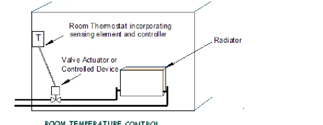
Figure below illustrates a basic control loop for room heating. In this example the thermostat
assembly contains both the sensor and the controller. The purpose of this control loop is to maintain the controlled variable (room air temperature) to some desired value, called a setpoint. Heat energy necessary to accomplish the heating is provided by the radiator and the controlled device is the 2-way motorized or solenoid valve, which controls the flow of hot water to the radiator.
Theory of Controls
Basically there are two types of controls viz. open loop control and closed loop control.
Open loop control
Open loop control is a system with no feedback i.e. there is no way to monitor if the control system is working effectively. Open loop control is also called feed forward control.
In open loop control the controller may operate an actuator or switch and is often done by a timer and is best explained by the following example of a cooking oven. If the required temperature inside the oven is achieved by switching on and off a heating element, this is known as sequence or open loop control. A timer is set by the operator which operates the electrical circuit to the electric heating element. Once the oven reaches the desired temperature, the timer will “close” the switch so that the temperature inside the oven modulates about a setpoint.
For the oven to maintain a constant temperature the element is switched on and off by a pre-set timing device which opens or closes the switch by a cam driven device. The resultant temperature inside the oven is not really constant but varies due to lag in achieving steady state conditions.
For more accurate control it would be best to keep the band width between on and off temperatures as narrow as is practicable. Too much switching will wear out the switch contacts especially if there is arcing across the switch contacts. It is evident that there is a relationship between switching time or switching cycle time and how often the temperature inside the oven is at the desired value. The diagram below shows the same open loop control but with reduced switching time. The oven temperature is more likely to be at or near the setpoint.
These types of controls are not suitable for air-conditioning and refrigeration system because it does not provide the facility of comparing the parameters to be controlled.
Closed Loop System
If the oven in the example had a temperature measuring device and the temperature inside was continually being compared with the desired temperature then this information could be used to adjust the amount of heat input to the electric element. In the closed system, controller responds to error in controlled variable. A comparison of the sensed parameters is made with respect to the set
parameters and accordingly the corresponding signals shall be generated. Closed loop control is also called feedback control.
In general ask a question, does sensor measure controlled variable? If yes the control system is closed loop, if no the system is open loop.
HVAC control systems are typically closed loops. Closed loop can be broadly classified into two categories viz. two position controls and continuous controls. Consider an example below of the temperature control of space heating. The diagram shows a room heated by a hot water radiator.
The control elements include: 1) Sensor
2) Controller
3) Controlled device - Valve actuator & valve
Note that the controlled variable; air temperature is what needs to be controlled. By varying the amount of hot water passing through the valve, the amount of heat being distributed to the room is controlled. This control sequence can be represented on a block diagram as shown below.
The desired value or setpoint is adjusted at the knob on the front of the thermostat. (Note that the room thermostat contains the sensor, setpoint adjustment, comparison device and the controller, which are shown distinctly in the block diagram above). The temperature sensor measures the actual value and sends a signal back along the feedback path to the comparison device. The comparison device compares the value of temperature at the sensor to that of the desired value or setpoint on the controller. The difference between the desired value and the measured value is known as the error signal. The error signal is fed into the controller as a low voltage signal (e.g. 10 volts) to the actuator. The controlled device, which is an actuator on 2-port valve reacts to the impulse received from the controller and varies the flow of the hot water. This in turn changes the condition of the space or process to the desired value. This type of control is called modulated control because the control elements are constantly changing the signal from the comparison device to maintain a near constant temperature in the room even though inside and outside conditions may vary.
Type of Control Systems
Direct Acting Systems
The simplest form of controller is direct-acting, comprising a sensing element which transmits power to a valve through a capillary, bellows and diaphragm. The measuring system derives its energy from the process under control without amplification by any auxiliary source of power which makes it simple and easy to use. The most common example is the thermostatic radiator valve which adjusts the valve by liquid expansion or vapor pressure. Direct-acting thermostats have little power and have some disadvantages but the main advantage is individual and inexpensive emitter control. Direct-acting thermostatic equipment gives gradual movement of the controlling device and may be said to modulate.
Electric / Electronic Systems
Electric controlled devices provide ON / OFF or two-position control. In residential and small commercial applications, low voltage electrical controls are most common. A transformer is used to reduce the 115 volt alternating current (AC) to a nominal 24 volts. This voltage signal is controlled by thermostats, and can open gas solenoid valves, energize oil burners or solenoid valves on the DX
cooling, control electric heat, operate two position valves and damper or turn on-off fans and pumps. A relay or contactor is used to switch line voltage equipment with the low voltage control signal. The advantage of electric system is that it eliminates the personnel safety and fire risk associated with line voltage, and allows these control wires to be installed by a non-electrician without requiring conduit and other safety measures. However, these systems are generally limited to providing on/off control only: they cannot operate at half capacity.
Electronic Controlled Devices can be either modulating or two-position (ON/OFF). Electronic control
systems usually have the following characteristics: 1) Controller: Low voltage, solid state
2) Inputs: 0 to 1V dc, 0 to 10V dc, 4 to 20 mA, resistance element, thermistor, and thermocouple 3) Outputs: 2 to 10V dc or 4 to 20 mA device
4) Control Mode: Two-position, proportional or proportional plus integral (PI) Other features of electronic control systems include:
1) Controllers can be remotely located from sensors and actuators. 2) Controllers can accept a variety of inputs.
3) Remote adjustments for multiple controls can be located together, even though sensors and actuators are not.
4) Electronic control systems can accommodate complex control and override schemes. 5) Universal type outputs can interface many different actuators.
6) Display meters indicate input or output values.
An electronic control system can be enhanced with visual displays that show system status and operation. Many electronic controllers have built-in indicators that show power, input signal, deviation signal, and output signal. An indicator light can show on/off status or, if driven by controller circuits, the brightness of a light can show the relative strength of a signal.
Pneumatic Systems
The most popular control system for large buildings historically has been pneumatics which can provide both On-Off and modulating control. Pneumatic actuators are described in terms of their spring range. Common spring ranges are 3 to 8 psig (21 to 56 kPa), 5 to 10 psig (35 to 70 kPa), and 8 to 13 psig (56 to 91 kPa).
Compressed air with an input pressure can be regulated by thermostats and humidistat. By varying the discharge air pressure from these devices, the signal can be used directly to open valves, close dampers, and energize other equipment. The copper or plastic tubing carry the control signals around the building, which is relatively inexpensive. The pneumatic system is very durable, is safe in
hazardous areas where electrical sparks must be avoided, and most importantly, is capable of modulation, or operation at part load condition. While the 24-volt electrical control system could only energize a damper fully open or fully closed, a pneumatic control system can hold that damper at 25%, 40% or 80% open. This allows more accurate matching of the supply with the load.
Pneumatic controls use clean, dry & oil free compressed air, both as the control signal medium and to drive the valve stem with the use of diaphragms. It is important that dirt, moisture and oil are absent
from the compressed air supply. Instrument quality compressed air is more suitable for controls rather than industrial quality and requires drying to a dew-point low enough to satisfy the application. The main disadvantages are: it is less reliable and noisier when compared to electronic systems.
Microprocessor Systems
Direct Digital Control (DDC) is the most common deployed control system today. The sensors and output devices (e.g., actuators, relays) used for electronic control systems are usually the same ones used on microprocessor-based systems. The distinction between electronic control systems and microprocessor-based systems is in the handling of the input signals. In an electronic control system, the analog sensor signal is amplified, and then compared to a setpoint or override signal through voltage or current comparison and control circuits. In a microprocessor-based system, the sensor input is converted to a digital form, where discrete instructions (algorithms) perform the process of comparison and control. Most subsystems, from VAV boxes to boilers and chillers, now have an
onboard DDC system to optimize the performance of that unit. A communication protocol known as BACNet is a standard protocol that allows control units from different manufacturers to pass data to each other.
Mixed Systems
Combinations of controlled devices are possible. For example, electronic controllers can modulate a pneumatic actuator. Also, proportional electronic signals can be sent to a device called transducer,
which converts these signals into proportional air pressure signals used by the pneumatic actuators. These are known as electronic-to-pneumatic (E-P) transducers. For example, electronic-to- pneumatic (E/P) transducer converts a modulating 2 to 10V DC signal from the electronic controller to a
pneumatic proportional modulating 3 to 13 psi signal for a pneumatic actuator. A sensor-transducer assembly is called a transmitter.
The input circuits for many electronic controllers can accept a voltage range of 0 to 10V dc or a current range of 4 to 20 mA. The inputs to these controllers are classified as universal inputs because they accept any sensor having the correct output. These sensors are often referred to as transmitters
as their outputs are an amplified or conditioned signal. The primary requirement of these transmitters is that they produce the required voltage or current level for an input to a controller over the desired sensing range. Transmitters measure variable conditions such as temperature, relative humidity, airflow, and water flow, power consumption, air velocity, and light intensity. An example of a
transmitter would be a sensor that measures the level of carbon dioxide (CO2) in the return air of an air-handling unit. The sensor provides a 4 to 20 mA signal to a controller input, which can then modulate outdoor/exhaust dampers to maintain acceptable air quality levels. Since electronic
controllers are capable of handling voltage, amperage, or resistance inputs, temperature transmitters are not usually used as controller inputs within the ranges of HVAC systems due to their high cost and added complexity. Summarizing
*Transducer changes the sensor signal to an electrical signal (e.g. a pressure into a voltage)
*Transmitter is the electronic circuitry to enable a suitable strength voltage proportional to the sensed parameter to be sent to a controller.
SENSORS
Sensors measure the controlled medium and provide a controller with information concerning changing conditions in an accurate and repeatable manner. The common HVAC variables are temperature, pressure, flow rate and relative humidity.
The siting of sensors is critical to achieve good control. In sensing space conditions, the sensing device must not be in the path of direct solar radiation or be located on a surface which would give a false reading such as a poorly insulated external wall.
In pipework or ductwork, sensors must be arranged so that the active part of the device is immersed fully in the fluid and that the position senses the average condition. Sometimes averaging devices are used to give an average reading of measured variable for example in large spaces having number of sensors, an averaging signal is important for the controller.
Type of Sensors
Different types of sensors produce different types of signals.
1) Analog sensors are used to monitor continuously changing conditions. The analog sensor provides the controller with a varying signal such as 0 to 10V.
2) A digital sensor is used to provide two position open or closed signal such as a pump that is on or off. The digital sensor provides the controller with a discrete signal such as open or closed contacts.
Some electronic sensors use an inherent attribute of their material (e.g., wire resistance) to provide a signal and can be directly connected to the electronic controller. For example, a sensor that detects pressure requires a transducer or transmitter to convert the pressure signal to a voltage or current signal usable by the electronic controller. Some sensors may measure other temperatures, time of day, electrical demand condition, or other variables that affect the controller logic. Other sensors input data that influence the control logic or safety, including airflow, water flow, and current, fire, smoke, or high/low temperature limit. Sensors are an extremely important part of the control system and can be a weak link in the chain of control. A sensor-transducer assembly is called a transmitter.
Classification of Sensors
Typical sensors used in electronic control systems are:
1) Resistance sensors are ‘Resistance Temperature Devices (RTD’s)’ and are used in measuring temperature. Examples are BALCO elements, Copper, Platinum, 10K Thermistors, and 30K Thermistors.
2) Voltage sensors could be used for temperature, humidity and pressure. Typical voltage input ranges are 0 to 5 Vdc (Volts direct current), 1 to 11 Vdc, and 0 to 10 Vdc.
3) Current sensors could be used for temperature, humidity, and pressure. The typical current range is 4 to 20 mA (milliamps).
One of the most common properties measured in the HVAC control is temperature. The principle of measurement involves- the thermal expansion of metal or gas and a calibrated change in electrical characteristics. Below are common types of temperature sensors:
Bi-Metallic Strip
The figure below shows a simple bi-metallic type thermostat with closing point contacts.
Sealed Bellows
The sealed bellows type is filled with a gas, vapor or liquid, which responds to change in temperature by variation in volume and pressure causing expansion or contraction.
Bulb & Capillary Sensors
Bulb and capillary elements are used where temperatures are to be measured in ducts, pipes, tanks or similar locations remote from the controller.
The bulb is filled with liquid, gas or refrigerant depending on the temperature range required. Expansion of the fluid in the heated bulb exerts a pressure which is transmitted by the capillary to the diaphragm and there translated into movement.
Electronic Sensors
The electronic temperature sensors are classified in three categories; 1) Resistance Temperature Devices (RTD), 2) Thermistors and 3) Thermocouples
Resistance Temperature Devices (RTD):
Resistance Temperature Detectors (RTD) operates on the principle that the electrical resistance of a metal changes predictably and in an essentially linear and repeatable manner with changes in temperature. RTD have a positive temperature coefficient (resistance increases with temperature). The resistance of the element at a base temperature is proportional to the length of the element and the inverse of the cross sectional area.
Common materials used in RTD sensor are BALCO wire, Copper, Platinum, 10K Thermistors, and 30K Thermistors.
a) BALCO - A sensor constructed using a BALCO wire is an annealed resistance alloy with a nominal composition of 70 percent nickel and 30 percent iron. A BALCO 500-ohm resistance element provides a relatively linear resistance variation from –40 to 250°F. The sensor is a low-mass device and responds quickly to changes in temperature. When 1000 ohms is measured across the BALCO element, the temperature is approximately 70°F. As the temperature
increases, the resistance changes 2.2 ohms per 1°F. This is called a Temperature Coefficient of Resistance Curve (TCR Curve). In a BALCO, as the resistance has direct relationship with temperature i.e. as temperature increases, the resistance increases proportionally. The usual range of temperature measurement with BALCO is -40° to 240°F.
b) Platinum - RTD sensors using platinum material exhibit linear response and stable over time. In some applications a short length of wire is used to provide a nominal resistance of 100 ohms. However, with a low resistance value, element self-heating and sensor lead wire resistance can effect the temperature indication. With a small amount of resistance change of the element, additional amplification must be used to increase the signal level. Platinum film sensor on an insulating base provides high resistance to the tune of 1000 ohms at 74°F. With this high resistance, the sensor is relatively immune to self-heating and responds quickly to changes in temperature. RTD elements of this type are common.
Advantages: Linear resistance with temperature, good stability, wide range of operating temperature
Interchangeable over wide temperature range
Disadvantages: Small resistance change with temperature, responses may be slower, subject to self heating, transmitter or three to four wire leads required for lead resistance compensation, external circuit power required
Additional facts
1) RTD's are commonly used in sensing air and liquid temperatures in pipes and ducts, and as room temperature sensors. The resistance of RTD elements varies as a function of temperature. Some elements exhibit large resistance changes, linear changes, or both over wide temperature ranges. 2) Varying voltage across the sensor element determines the resistance of the sensor. The power
supplied for this purpose can cause the element to heat slightly and can create an inaccuracy in the temperature measurement. Reducing supply current or by using elements with higher nominal resistance can minimize the self-heating effect.
3) Some RTD element resistances are as low as 100 ohms. In these cases, the resistance of the lead wires connecting the RTD to the controller may add significantly to the total resistance of the connected RTD, and can create an error in the measurement of the temperature. For instance, a sensor placed 25 feet from the controller has a copper control wire of 25 x 2 = 50 feet. If a control wire has a DC resistance of 6.39 ohms/ft, the 50 feet of wire shall have a total dc resistance of 0.319 ohms. If the sensor is a 100-ohm platinum sensor with a temperature coefficient of 0.69 ohms per degree F, the 50 feet of wire will introduce an error of 0.46 degrees F. If the sensor is a 3000-ohm platinum sensor with a temperature coefficient of 4.8 ohms per degree F, the 50 feet of wire will introduce an error of 0.066 degrees F.
Therefore lesser is the resistance of sensor element, higher shall be the likelihood of error. Significant errors can be removed by adjusting a calibration setting on the controller, or, if the controller is designed for it, a third wire can be run to the sensor and connected to a special compensating circuit designed to remove the lead length effect on the measurement.
Thermistors
Thermistors are temperature sensitive semiconductors that exhibit a large change in resistance over a relatively small range of temperature. There are two main types of thermistors, positive temperature coefficient (PTC) and negative temperature coefficient (NTC). NTC thermistors exhibit the
characteristic of falling resistance falling with increasing temperature. These are most commonly used for temperature measurement.
Unlike RTD's, the temperature-resistance characteristic of a thermistor is non-linear, and cannot be characterized by a single coefficient. Manufacturers commonly provide resistance-temperature data in curves, tables or polynomial expressions. Linearizing the resistance-temperature correlation may be accomplished with analog circuitry, or by the application of mathematics using digital computation.
Advantages: Large resistance change with temperature, rapid response time, good stability, High resistance eliminates difficulties caused by lead resistance, Low cost and interchangeable
Disadvantages: Non-linear, limited operating temperature range, may be subjected to inaccuracy
due to overheating, current source required
Thermocouples
Thermocouples have two dissimilar metal wires joined at one end. Temperature differences at the junctions’ causes a voltage, in the mill volt range, which can be measured by the input circuits of an electronic controller. The output is a voltage proportional to the temperature difference between the junction and the free ends. By holding one junction at a known temperature (reference junction) and measuring the voltage, the temperature at the sensing junction can be deduced. The voltage generated is directly proportional to the temperature difference.
At room temperatures for typical HVAC applications, these voltage levels are often too small to be used, but are more usable at higher temperatures of 200 to 1600°F. Consequently, thermocouples are most common in high-temperature process applications.
Advantages: Widest operating range, simple, low cost and no external power supply required. Disadvantages: Non-linear, low stability relative to other types, reference junction temperature
compensation required
Relative Humidity Sensors
Various sensing methods are used to determine the percentage of relative humidity, including the measurement of changes of resistance, capacitance, impedance, and frequency. Fabrics which change dimension with humidity variation, such as hair, nylon or wood, are still in use as measuring elements but are unreliable - hygroscopic plastic tape is now more common. These media may be used to open or close contacts or to operate a potentiometer. For electronic applications, use is made of a hygroscopic salt such as lithium chloride, which will provide a change in resistance depending upon the amount of moisture absorbed. Solid state sensors use polymer film elements to produce variations in resistance or capacitance.
Resistance Relative Humidity Sensor
A method that uses change in resistance to determine relative humidity works on a layer of
hygroscopic salt such as lithium chloride deposited between two electrodes. Both materials absorb and release moisture as a function of the relative humidity, causing a change in resistance of the sensor. An electronic controller connected to this sensor detects the changes in resistance, which it can use to provide control of relative humidity.
Capacitance Relative Humidity Sensor
A method that uses changes in capacitance to determine relative humidity measures the capacitance between two conductive plates separated by a moisture sensitive material such as polymer plastic. As
the material absorbs water, the capacitance between the plates decreases and the change can be detected by an electronic circuit. To overcome any hindrance of the material’s ability to absorb and release moisture, the two plates and their electric lead wires can be on one side of the polymer plastic and a third sheet of extremely thin conductive material on the other side of the polymer plastic form the capacitor. This third plate, too thin for attachment of lead wires, allows moisture to penetrate and be absorbed by the polymer thus increasing sensitivity and response. Because of the nature of the measurement, capacitance humidity sensors are combined with a transmitter to produce a higher-level voltage or current signal. Key considerations in selection of transmitter sensor combinations include range, temperature limits, end-to-end accuracy, resolution, long-term stability, and interchangeability.
Capacitance type relative humidity sensor/transmitters are capable of measurement from 0-100 % relative humidity with application temperatures from -40 to 200 °F. These systems are manufactured to various tolerances, with the most common being accurate to ±1%, ±2%, and ±3%. Capacitance sensors are affected by temperature such that accuracy decreases as temperature deviates from the calibration temperature. Sensors are available that are inter-changeable within plus or minus 3% without calibration. Sensors with long term stability of <±1% per year are also available.
Temperature Condensation
Both temperature and percent RH affect the output of all absorption based humidity sensors.
Applications calling for either high accuracy or wide temperature operating range require temperature compensation. The temperature should be made as close as possible to the RH sensors active area. This is especially true when using RH and temperature to measure dew- point.
Condensation & Wetting
Condensation occurs whenever the sensors surface temperature drops below the dew point of the surrounding air, even if only momentarily. When operating at levels of 95% RH and above small temperature changes can cause condensation.
Under these conditions where the ambient temperature and the dew point are very close,
condensation forms quickly, but the moisture takes a long time to evaporate. Until the moisture is gone the sensor outputs a 100% RH signal.
Quartz Crystal Relative Humidity Sensor
Sensors that use changes in frequency to measure relative humidity can use a quartz crystal coated with a hygroscopic material such as polymer plastic. When an oscillating circuit energizes the quartz crystal, it generates a constant frequency. As the polymer material absorbs moisture and changes the mass of the quartz crystal, the frequency of oscillation varies and can be measured by an electronic circuit.
Most relative humidity sensors require electronics at the sensor to modify and amplify the weak signal and are referred to as transmitters. The electronic circuit compensates for the effects of temperature as well as amplifies and linearizes the measured level of relative humidity. The transmitter typically provides a voltage or current output that can be used as an input to the electronic controller. When operating in high RH (90% and above), consider these strategies:
2. Use a sintered stainless steel filter to protect the sensor from splashing. A hydrophobic coating can also suppress condensation and wetting in rapidly saturating/ de-saturating or splash prone
environment.
3. Heat the RH sensor above the ambient dew point temperature.
NOTE: Heating the sensor changes the calibration and makes it sensitive to thermal disturbances such as airflow.
Pressure Sensors
Diverse electrical principles are applied to pressure measurement. Those commonly used include capacitance and variable resistance (piezoelectric and strain gage).
Variable Resistance
Variable resistance technology includes both strain gage and piezoelectric technologies. An electronic pressure sensor converts pressure changes into a signal such as voltage, current, or resistance that can be used by an electronic controller. A method that measures pressure by detecting changes in resistance uses a small flexible diaphragm and a strain gage assembly. The strain gage assembly includes very fine (serpentine) wire or a thin metallic film deposited on a nonconductive base. The strain gage assembly is stretched or compressed as the diaphragm flexes with pressure variations. The stretching or compressing of the strain gage changes the length of its fine wire/thin film metal, which changes the total resistance. The resistance can then be detected and amplified. These changes in resistance are small. Therefore, an amplifier is provided in the sensor assembly to amplify and condition the signal so the level sent to the controller is less susceptible to external noise
interference. The sensor thus becomes a transmitter. The pressure sensing motion may be
transmitted directly to an electric or pneumatic control device. In electronic systems, the diaphragm or the sensing element is connected to a solid state device which when distorted changes resistivity. This is known as the piezo-electric effect.
Capacitance
Another pressure sensing method measures capacitance. A fixed plate forms one part of the
capacitor assembly and a flexible plate is the other part of the capacitor assembly. As the diaphragm flexes with pressure variations, the flexible plate of the capacitor assembly moves closer to the fixed plate and changes the capacitance. A variation of pressure sensors is one that measures differential pressure using dual pressure chambers. The force from each chamber acts in an opposite direction with respect to the strain gage. This type of sensor can measure small differential pressure changes even with high static pressure.
Flow Sensors
Liquid flowrate can be obtained by measuring a velocity of a fluid in a duct or pipe and multiplying by the known cross sectional area (at the point of measurement) of that duct or pipe. Common methods used to measure liquid flow include differential pressure measurement difference across a restriction to flow (orifice plate, flow nozzle, venture), vortex shedding sensors, positive displacement flow sensors, turbine based flow sensors, magnetic flow sensors, ultrasonic flow sensors and ‘target’ flow sensors.
Orifice
A concentric orifice plate is the simplest differential pressure type meters that constrict the flow of a fluid to produce a differential pressure across the plate. The result is a high pressure upstream and a low pressure downstream that is proportional to the square of the flow velocity. An orifice plate usually produces a greater overall pressure loss than other flow elements. An advantage of this device is that cost does not increase significantly with pipe size.
Venturi Tube
The Venturi tube meter consists of a rapidly converging section which increases the velocity of flow and hence reduces the pressure. It then returns to the original dimensions of the pipe by a gently diverging 'diffuser' section. By measuring the pressure differences, the discharge can be calculated. This is a particularly accurate method of flow measurement and the energy losses are very small.
Venturi tubes exhibit a very low pressure loss compared to other differential pressure meters, but they are also the largest and most costly. Venturi tube applications are generally restricted to those
requiring a low pressure drop and a high accuracy reading. They are widely used in large diameter pipes.
Flow Nozzles
Flow nozzles may be thought of as a variation on the Venturi tube. The nozzle opening is an elliptical restriction in the flow but with no outlet area for pressure recovery. Pressure taps are located
approximately 1/2 pipe diameter downstream and 1 pipe diameter upstream. The flow nozzle is a high velocity flow meter used where turbulence is high (Reynolds numbers above 50,000) such as in steam flow at high temperatures. The pressure drop of a flow nozzle falls between that of the Venturi tube and the orifice plate (30 to 95 percent).
The turndown (ratio of the full range of the instrument to the minimum measurable flow) of differential pressure devices is generally limited to 4:1. With the use of a low range transmitter in addition to a high range transmitter or a high turndown transmitter and appropriate signal processing, this can sometimes be extended to as great as 16:1 or more. Permanent pressure loss and associated energy cost is often a major concern in the selection of orifices, flow nozzles, and venturis. In general, for a given installation, the permanent pressure loss will be highest with an orifice type device, and lowest with a Venturi. Benefits of differential pressure instruments are their relatively low cost, simplicity, and proven performance.
Vortex Shedding Sensors
Vortex shedding flow meters operate on the principle (Von Karman) that when a fluid flows around an obstruction in the flow stream, vortices are shed from alternating sides of the obstruction in a
repeating and continuous fashion. The frequency at which the shedding alternates is proportional to the velocity of the flowing fluid. Single sensors are applied to small ducts, and arrays of vortex shedding sensors are applied to larger ducts, similar to the other types of airflow measuring instruments. Vortex shedding airflow sensors are commonly applied to air velocities in the range of 350 to 6000 feet per minute.
Positive Displacement Flow Sensors
Positive displacement meters are used where high accuracy at high turndown is required and reasonable to high permanent pressure loss will not result in excessive energy consumption.
Applications include water metering such as for potable water service, cooling tower and boiler make-up, and hydronic system make-up. Positive displacement meters are also used for fuel metering for both liquid and gaseous fuels. Common types of positive displacement flow meters include lobed and gear type meters, nutating disk meters, and oscillating piston type meters. These meters are typically constructed of metals such as brass, bronze, cast and ductile iron, but may be constructed of
engineered plastic, depending on service.
Turbine Based Flow Sensors
Turbine and propeller type meters operate on the principle that fluid flowing through the turbine or propeller will induce a rotational speed that can be related to the fluid velocity. Turbine and propeller type flow meters are available in full bore, line mounted versions and insertion types where only a portion of the flow being measured passes over the rotating element. Full bore turbine and propeller meters generally offer medium to high accuracy and turndown capability at reasonable permanent pressure loss. Turbine flow meters are commonly used where good accuracy is required for critical flow control or measurement for energy computations. Insertion types are used for less critical applications. Insertion types are often easier to maintain and inspect because they can be removed for inspection and repair without disturbing the main piping.
Magnetic Flow Sensors
Magnetic flow meters operate based upon Faraday's Law of electromagnetic induction, which states that a voltage will be induced in a conductor moving through a magnetic field.
Faraday's Law: E=kBDV
The magnitude of the induced voltage E is directly proportional to the velocity of the conductor V, conductor width D, and the strength of the magnetic field B. The output voltage E is directly proportional to liquid velocity, resulting in the linear output of a magnetic flow meter. Magnetic flow meters are used to measure the flow rate of conducting liquids (including water) where a high quality low maintenance measurement system is desired. The cost of magnetic flow meters is high relative to many other meter types.
Ultrasonic Flow Sensors
Ultrasonic flow sensors measure the velocity of sound waves propagating through a fluid between to points on the length of a pipe. The velocity of the sound wave is dependant upon the velocity of the fluid such that a sound wave traveling upstream from one point to the other is slower than the velocity of the same wave in the fluid at rest. The downstream velocity of the sound wave between the points is greater than that of the same wave in a fluid at rest. This is due to the Doppler Effect. The flow of the fluid can be measured as a function of the difference in time travel between the upstream wave and the downstream wave.
Ultrasonic flow sensors are non-intrusive and are available at moderate cost. Many models are designed to clamp on to existing pipe. Ultrasonic Doppler flow meters have accuracies of 1 to 5% to the flow rate.
Air Flow Measurements
Common methods for measuring airflow include hot wire anemometers, differential pressure measurement systems, and vortex shedding sensors.
Hot Wire Anemometers
Anemometers operate on the principle that the amount of heat removed from a heated temperature sensor by a flowing fluid can be related to the velocity of that fluid. Most sensors of this type are constructed with a second, unheated temperature sensor to compensate the instrument for variations in the temperature of the air. Hot wire type sensors are better at low airflow measurements than differential pressure types, and are commonly applied to air velocities from 50 to 12,000 feet per minute.
Pitot – Static Tube
The Pitot - static tube can be used to measure total pressure and static pressure through the
ductwork. The diagram below shows a typical Pitot-static tube. The tube facing the air stream is called the facing tube and measures the total head. The static head is obtained from the small tapings into the annulus. The head difference as measured in the manometer is therefore the Velocity head.
The velocity can be found from the following formula:
Total pressure = Static pressure + Velocity pressure Velocity pressure (VP) = Total pressure - Static pressure
Where:
Velocity = Velocity (ft/min) VP = velocity pressure (in w.c.) p = density of air (lbm/ft2)
gc = gravitational constant (32.174 lbm× ft/lbf×s2) C = unit conversion factor (136.8)
To convert from head to pressure use the following formula:
Pressure = density of liquid in manometer x acceleration due to gravity (9.81m/s2) x head (meters). Figure below depicts an example of a velocity pressure measurement with a U tube manometer and the relationship between velocity pressures (VP), static pressure, and total pressure.
In large ducts an array of sensing devices is required to obtain an average air velocity.
Dew Point Measurements
Dew point is the temperature to which air must be cooled under constant pressure to cause
condensation to occur. It can be an important parameter to consider in some HVAC applications were possible condensation is undesirable and therefore must be measured and controlled. Dew point measurements for use in HVAC control systems are typically made by one of two methods. One method is by measuring temperature and relative humidity correctly and calculating the dew point using empirical mathematical formulas. The second is by direct measurement using a chilled mirror type sensor.
Calculation from Temperature and Relative Humidity
It is common practice when measuring relative humidity to combine a temperature sensor and
transmitter into the same device as the humidity sensor. Using a microprocessor, it is then possible to calculate and transmit dew point. Accuracy is limited by the combined accuracy of the sensors and the electronics. Typical accuracy is ±1.8 °F. Typical repeatability is ±0.7 °F. Commonly, these devices can be configured to output calculated humidity ratio, wet bulb temperature, and absolute humidity as well as dew point.
Chilled Mirror Hygrometers
Modern chilled mirror hygrometers use a thermoelectric heat pump (also called a Peltier device) to move heat away from a mirror. A light beam from an LED is directed to the mirror and back to a photocell. When condensation (above 0 °C) or frost (below 0 °C) forms on the mirror’s surface, the light reaching the mirror is scattered and the intensity detected by the photocell is reduced. The mirror is maintained at the dew point temperature by controlling the output of the thermoelectric heat pump. A high accuracy, platinum resistance thermometer (RTD) senses the temperature of the mirror’s surface and therefore reports the dew point temperature. Chilled mirror hygrometers require a vacuum pump to draw the sample through the sensor, and additional filtration elements in dirty environments. Chilled mirror hygrometers are available for sensing dew/frost point temperatures from -100 to 185 °F. Accuracy of better than ± 0.5 °F is available.
Liquid Level Measurements
Liquid level measurements are typically used to monitor and control levels in thermal storage tanks, cooling tower sumps, water system tanks, pressurized tanks, etc. Common technologies applicable to
HVAC system requirements are based on hydrostatic pressure, ultrasonic, capacitance and magnetostrictive-based measurement systems.
Hydrostatic
Level measurement by hydrostatic pressure is based on the principle that the hydrostatic pressure difference between the top and bottom of a column of liquid is related to the density of the liquid and the height of the column. For open tanks and sumps, it is only necessary to measure the gauge pressure at the lowest monitored level. For pressurized tanks it is necessary to take the reference pressure above the highest monitored liquid level. Pressure transmitters are available that are configured for level monitoring applications. Pressure instruments may also be remotely located, however this makes it necessary to field calibrate the transmitter to compensate for elevation difference between the sensor and the level being measured.
Bubbler type hydrostatic level instruments have been developed for use with atmospheric pressure underground tanks, sewage sumps and tanks, and other applications that cannot have a transmitter mounted below the level being sensed or are prone to plugging. Bubbler systems bleed a small amount of compressed air (or other gas) through a tube that is immersed in the liquid, with an outlet at or below the lowest monitored liquid level. The flow rate of the air is regulated so that the pressure loss of the air in the tube is negligible and the resulting pressure at any point in the tube is
approximately equal to the hydrostatic head of the liquid in the tank. The accuracy of hydrostatic level instruments is related to the accuracy of the pressure sensor used.
Ultrasonic
Ultrasonic level sensors emit sound waves and operate on the principle that liquid surfaces reflect the sound waves back to the source and that the transit time is proportional to the distance between the liquid surface and the transmitter. One advantage of the ultrasonic technology is that it is non-contact and does not require immersion of any element into the sensed liquid. Sensors are available that can detect levels up to 200 feet from the sensor. Accuracy from 1% to 0.25% of distance and resolution of 1/8" is commonly available.
Capacitance
Capacitance level transmitters operate on the principle that a capacitive circuit can be formed between a probe and a vessel wall. The capacitance of the circuit will change with a change in fluid level because all common liquids have dielectric constant higher than that of air. This change is then related proportionally to an analog signal.
CONTROLLERS
The controller receives signals from the sensor, compares inputs with set of instructions such as setpoint, throttling range, applies control logic and than produces an output signal. The output signal may be transmitted either to the controlled device or to other logical control functions. Type of signals from the controllers can be electric, electronic, pneumatic or digital. The electronic signals could either be voltage or current outputs. Voltage outputs may be 0 to 10 Vdc, 2 to 15 Vdc, or other ranges depending on the controller. Voltage outputs have the disadvantage, when compared to current signals, that voltage signals are more susceptible to distortion over long wire distances. Current outputs modulate from 4 to 20 mA. They have the advantage of producing little signal distortion over long wire distances.
Controller Action
All controllers, from pneumatic to electronic, have an action. They are either ‘Direct Acting’ or ‘Reverse Acting’.
Direct Action
Direct Action means that the controller's output increases as the sensor's input increases. For
example, as room temperature (the variable) changes from 70°F to 71°F, the controller changes its output from 10 to 12 mA. Shown below, as the sensor reads an increasing input (temperature), the controller responds by increasing its output (pressure) to the valve, closing the normally open valve and reducing the hot water flow:
65 F 70 F 75 F 80 F 5 0 20 15 10 mA Room Temperature DIRECT ACTION CONTROLLER
Reverse Action
Reverse Action means that as the variable (for example, temperature) increases, the controller's output decreases. For example, as room temperature rises from 70 to 71°F, the controller output
decreases from 8.1 to 7.3 mA. In the example below, as the sensor reads an increasing temperature, the controller responds by decreasing its output (pressure) to the valve, closing the normally closed valve and reducing the amount of heating. This relationship is displayed on a graph as follows:
6 5 F 7 0 F 7 5 F 8 0 F 5 0 2 0 1 5 1 0 m A R o o m T e m p e r a t u r e R E V E R S E A C T I O N C O N T R O L L E R
The action of the controller must match the proper HVAC application. Normally open heating valves always use direct acting controllers. If a reverse acting controller were to be placed on a normally open heating valve, the heating valve would open as temperature rises. A reverse acting controller never properly controls a normally open heating valve.
Identifying Reverse or Direct Action
Identification of a controller action for different applications could be determined from the table below. To use the table, follow the steps below:
1) First pick the correct application: for temperature, select heating or cooling; for humidity, select humidification or dehumidification; for pressure, select whether the sensor is downstream or upstream from the controlled device.
2) The second step is to determine how the application fails. Example, does the heat fail to full ON or full OFF?
3) Third, once these questions are answered, follow the column down and follow the row across to the intersection to find the correct action for that application.
Controller Action Heating, Humidification, Pressure (sensed downstream from controlled device)
Cooling, Dehumidification, Pressure (sensed upstream from controlled device)
System Fails to ON
Normally open ports, valves or dampers
Normally closed electric contacts
Direct Action Reverse Action
System Fails to OFF
Normally closed ports, valves or dampers
Normally open electric contacts
Reverse Action Direct Action
How to use the Table; follow the examples & steps below:
Example #1:Chilled water air-conditioning cooling application requires controlling a normally open
1) Under normal operation, the chilled water valve is open and as the temperature decreases, the controller signals to close the normally open chilled water valve.
2) Since the valve is normally open, the “Fails to ON” row is used.
3) The column and the row intersect at Reverse Action. As the temperature increases, the signal
drops, allowing the chilled water valve to go to its normal open position. As the temperature decreases, the signal increases, closing the normally open chilled water valve.
Example # 2: A return air humidity sensor modulates a normally closed chilled water valve for dehumidification. What action is needed for the controller?
Direct Action
Example #3: A static pressure sensor (located on discharge side) modulates normally closed inlet vane dampers to maintain 2.0" w.c. (500 Pa). What action is needed for the controller?
Reverse Action
Example #4: A room sensor cycles DX cooling to maintain a room temperature of 75°F . The DX Cooling has normally open electrical contacts. What action is needed for the controller?
Direct Action
Example #5: The mixed air sensor (located on discharge side) modulates the normally closed outside air dampers and the normally open return air dampers to maintain a temperature of 55°F. What action is needed for the controller?
Direct Action
CONTROLLER TYPES
Temperature Controllers
Temperature Controller, as the name implies is an instrument used to control temperature. The temperature controller takes an input from a temperature sensor and has an output that is connected to a control element such as a heater or fan.
Temperature controllers typically require a specific type or category of input sensors. Some have input circuits to accept RTD sensors such as BALCO or platinum elements, while others contain input circuits for thermistor sensors. These controllers have setpoint and throttling range scales labeled in degrees F or C.
Relative Humidity Controllers
The input circuits for relative humidity controllers typically receive the sensed relative humidity signal already converted to a 0 to 10V dc voltage or 4-to 20 mA current signals. Setpoint and scales for these controllers are in percent relative humidity.
Enthalpy Controllers
Enthalpy controllers are specialized devices that use specific sensors for inputs. In some cases, the sensor may combine temperature and humidity measurements and convert them to a single voltage to represent enthalpy of the sensed air. In other cases, individual dry bulb temperature sensors and separate wet bulb or relative humidity sensors provide inputs and the controller calculates enthalpy. In typical applications, the enthalpy controller provides an output signal based on a comparison of two enthalpy measurements, indoor and outdoor, rather than on the actual enthalpy value. In other cases,
the return air enthalpy is assumed constant so that only outdoor air enthalpy is measured. It is compared against the assumed nominal return air value.
Universal Controllers
The input circuits of universal controllers can accept one or more of the standard
transmitter/transducer signals. The most common input ranges are 0 to 10V dc and 4 to 20 mA. Other input variations in this category include a 2 to 10V dc and a 0 to 20 mA signal. Because these inputs can represent a variety of sensed variables such as a current of 0 to 15 amperes or pressure of 0 to 3000 psi, the settings and scales are often expressed in percent of full scale only.
RESET
The “reset” in HVAC applications is the automatic resetting of a setpoint based on a secondary signal. Reset of a setpoint is used for comfort reasons, for better control, or to save energy. A common example of reset is called hot water reset. Hot water reset automatically decreases the hot water temperature setpoint as the outside air temperature rises. If the outside air temperature is 0°F, the building requires 180°F water and if the outside air temperature is 70°F, the building requires 90°F water. As the outside temperature increases, the hot water setpoint drops.
In every reset application there are at least two sensors- “primary and secondary sensors”. In the example above, the two sensors are outside air temperature (OA Temp) and hot water supply temperature (HWS). To determine which the primary sensor is, ask, "What are the controls trying to control?"
In the example above, the hot water temperature is being controlled; therefore the hot water sensor is the primary sensor. The outside air temperature sensor is the secondary sensor. The function of the secondary sensor is to reset or automatically change the setpoint of the controller. Each reset
application uses a reset schedule. This schedule is determined by the mechanical engineer or the application engineer.
Just as the term controller action is defined as reverse and direct, the term reset is also defined as reverse and direct. The hot water reset example is a reverse reset. Reverse reset is the most common.
Reverse Reset
Reverse reset means that as the signal from the secondary sensor drops, the setpoint of the controller increases. In the example above, as the outside air temperature drops, the hot water setpoint rises.
Direct Reset
With direct reset, as the signal for the secondary input increases, the setpoint increases. Direct reset is less common than reverse reset. An example of direct reset is an application called “summer compensation”, shown below.
When cooling (air conditioning) was first introduced, shopping malls advertised their stores as being a comfortable 72°F year round. This was fine until the summer became very hot. People who were outside in 100°F weather, dressed for hot weather, would walk into a shopping mall and feel cold. Some people did not stay long in the stores because it felt too cool. Summer compensation is used to
counteract this problem. Summer compensation raises the zone setpoint as the outside air temperature increases. The secondary signal and the setpoint go in the same direction. A typical reset schedule for this application may look like the following:
Summer Compensation Reset Schedule OA Temp Zone Setpoint
72°F 72°F 105°F 78°F
This application is used in any building where a large number of people are entering and leaving all day, such as a shopping mall or bank. If this application is used, it may be important to ensure that the air is dehumidified for proper comfort.
Identifying Reverse or Direct Reset
Looking at the reset schedule and note the relationship between the secondary signal and the setpoint. If the secondary signal increases as the setpoint decreases, then the application is reverse reset. Secondary Signal and Setpoint go in opposite directions. If the secondary signal increases as the setpoint increases, then it is direct reset. Secondary Signal and Setpoint go in the same direction.
Example #1
In the figure below, the hot water supply is maintained by On-Off control of electric input to the hot water generator. Here the hot water temperature is the primary sensor. The controller performs reverse action and it’s the reverse reset application.
Example #2
In the figure below, the return air humidity sensor controls the electric input to the pan type steam humidifier according to a reset schedule based on outside air temperature and relative humidity setpoint. Here the return air humidity (RAH) is a primary sensor. The controller performs reverse action and it’s the direct reset application.
Example #3
In the figure below, the mixed air temperature sensor controls the normally closed outside air dampers and the return air dampers. The outside air temperature is at 34°F. Here the mixed air temperature is the primary sensor. The controller performs direct action and it’s the reverse reset application.
CONTROLLED DEVICES
Most of HVAC plant control takes place through control valves regulating steam or hot/chilled water flow as the means of trimming heat transfer therefore their characteristics, sizing and selection are extremely important.
Control Valves
Control valves are used to maintain space temperature conditions by altering chilled/hot water flow. Valves can be two-position or modulating 3-port configuration. Two-way valves throttle flow while three- way divert flow. Two-way valves have two ports and are used to control the flow in variable flow systems. Three-way valves have three ports and can be piped for by-pass application either in mixing or diverting service. Bypass (diverting) applications are commonly used in constant flow systems where full flow across the coil is not required because of partial load system conditions. The control of
the flow through the terminal unit is typically accomplished by using a three-way valve. There are two basic arrangements for three-way valves: mixing valves (two inlets, one outlet) and diverting valves (one inlet, two outlets). The type of three-way valve selected will determine its location in the system. There are several different physical types of valves. Globe valves, ball valves and butterfly valves are all commonly used in the HVAC industry.
Mixing Valves
A three-port valve with two inlet flows and one common outlet flow is defined as a mixing valve, and so provides a variable temperature outlet at a constant flow rate. A three-port motorized valve can be used to MIX, in varying proportions, two flows of different temperatures while maintaining a constant rate of flow in the common outlet port. A Mixing Valve is used normally for radiator circuits.
Diverting Valves
3-port valve may also be used to DIVERT a common flow in varying proportions. The valve will have one inlet and two outlets and provides a constant temperature and variable flow rate. The diagram below shows a diverting valve with some typical water flow rates and temperatures. A diverting valve is used normally for circuits with convective heat transfer such as; heat exchangers, primary coil in