the future of air conditioning
Technical Catalog
5 kW ~14 kW (2HP ~ 6HP)
Heat Pump Air conditioners
• Cassette Type
• In the Ceiling Type
• Ceiling Type
• Floor Type
• Wall type
Specifications in this catalogue are subject to change without notice in order that HITACHI may bring the latest innovations to their customers
Whilst every effort is made to ensure that all dimensions and specifications are correct, any printers' errors not rectified are outside the control of HITACHI, who cannot be held
&217(176
02'(/6/,67 Models List Code Meaning3$57,7(&+1,&$/'$7$
81,76'(6&5,37,21 System Description RCI - Cassette Type
RPI - In-the-Ceiling Type
RPC - Ceiling Type
RPF - Floor type
RPK - Wall Type
RAS - Outdoor Unit
)($785(6
RCI - Cassette Type
RPI - In-the-Ceiling-Type
RPC - Ceiling Type
RPF - Floor type
RPK - Wall Type
RAS - Outdoor Unit
*(1(5$/'$7$ RCI - Cassette Type
RPI - In-the-Ceiling-Type
RPC - Ceiling Type
RPF - Floor type
RPK - Wall Type
RAS - Outdoor Unit
Components Detailed Data
',0(16,21$/'$7$ RCI - Cassette Type
RPI - In-the-Ceiling-Type
RPC - Ceiling Type
RPF - Floor type
RPK - Wall Type
RAS - Outdoor Unit
&22/,1*$1'+($7,1*&$3$&,7< Cooling Capacity Tables
Heating Capacity Tables
Correction Factors
Calculation example
:25.,1*5$1*( Power Supply
Temperature
Refrigerant Piping Length
5()5,*(5$17&<&/('(6&5,37,21 (/(&75,&$/'$7$ Indoor Unit Outdoor Unit (/(&75,&$/:,5,1*',$*5$06 ,1'225$1'287'22581,73&% Indoor Unit PCB Outdoor Unit PCB 3527(&7,21$1'6$)(7<&21752/ Compressor protection
Fan Motor protection
Safety summary and control devices
67$1'$5'&21752/)81&7,216 $9$,/$%/(237,21$/)81&7,216 5(027(&21752//(5623(5$7,21
Standard Remote Control Switch (PC-2H)
Optional Remote Control Switch (PC-5H)
Optional central Station (PSC-3S1)
Optional 7-Day Timer (PSC-3T)
Optional CS-NET
3$57,,,167$//$7,21'$7$
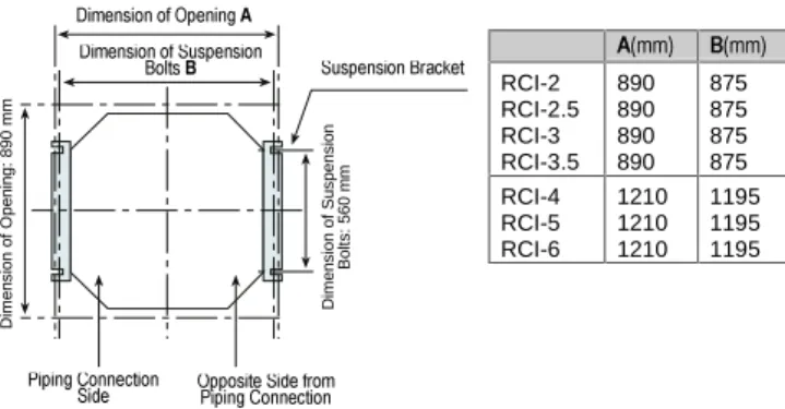
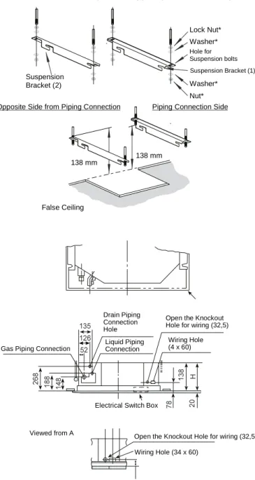
81,76,167$//$7,21 RCI - Unit installation
RPI - Unit installation
RPC - Unit installation
RPF - Unit installation
RPK - Unit installation
RAS - Outdoor Unit installation
5()5,*(5$173,3,1*$1'5()5,*(5$17 &+$5*(
Piping materials
Piping Connection for Indoor Unit
Piping Connection for Outdoor Unit
Piping and Refrigerant Charge
Piping in case of Twin Connection
Refrigerant Charging Quantity and Piping Size
'5$,13,3,1* (/(&75,&$/:,5,1*
General check
Electrical Wiring Connection for Outdoor Unit
Electrical Wiring Connection for Indoor Unit
Electrical wiring between indoor and outdoor unit
Wiring in case of Twin Connection
Wire Sizes
5(027(&21752//(56,167$//$7,21
Standard & Optional Remote Controllers Installation
One Standard Remote Controller (PC-2H) for multiple units. Wiring Connection and DIP Switch Setting
Optional Central Station (PCS-3S1), Wiring Connection and DIP Switch Setting
7(675811,1*
&+(&.)81&7,2186,1*7+(5(027( &21752/6:,7&+
Alarm Codes
Check MODE 1 and Check MODE 2
Self-checking of Remote Control Switch
Self-checking of PCB’s using RCS
Codes of abnormalities
7528%/(6+227,1*
02'(/6/,67
MODELS CODIFICATION ,PSRUWDQWQRWH3OHDVHFKHFNDFFRUGLQJWRWKHPRGHOQDPHZKLFKLV\RXUDLUFRQGLWLRQHUW\SH
DQGKRZLWLVDEEUHYLDWHGDQGUHIHUHHGWRLQWKLVWHFKQLFDOFDWDORJXH
,1'22581,7 287'22581,7
&DVVHWWH &HLOLQJ ,QWKHFHLOLQJ
Without
heater With heater
Without
heater With heater
)ORRU :DOO
Three phase Single phase
53,+4( 5&,+4( 53&+4( 53)+4( 5$6+49(
53,+4( 5&,+4( 53&+4( 53)+4( 5$6+4( 5$6+49(
53,+4( 5&,+4( 5&,+41( 53&+4( 53&+41( 53)+4( 53.+4 5$6+4( 5$6+49(
53,+4( 5&,+4( 53&+4( 5$6+4(
53,+4( 5&,+4( 5&,+41( 53&+4( 53&+41( 53.+4 5$6+4( 5$6+49(
53,+4( 5&,+4( 5&,+41( 53&+4( 53&+41( 5$6+4(
53,+4( 5&,+4( 5&,+41( 53&+4( 53&+41( 5$6+4(
3 ~ 1 ~
53,+ 5&,+ 5&,+1 53&+ 53&+1 53)+ 53.+ 5$6+ 5$6+9
&2'(0($1,1*
2XWGRRU8QLW ,QGRRU8QLW Compressor Power (HP) Unit Type Unit Type Compressor Power (HP) (Outdoor Unit) (Indoor Unit) A = Cooling Only H = Heat Pump Scroll Compressor Single Phase Series Number Made in Europe A = Cooling Only H = Heat Pump Scroll Compressor Series Number Made in Europe N = With Electric Heater (RCI & RPC only)3$57 ,
81,76'(6&5,37,21
6<67(0'(6&5,37,21
■This air conditioner is designed to offer cooling, heating, dry and fan operation.
■This air conditioner system is called Split System and consist in one outdoor unit connected to one indoor unit. The system is controlled by a remote control switch.
■Several sets of one indoor unit and one outdoor unit can be controlled by a single remote control switch.
EXAMPLE FOR CASSETTE TYPE
7+(7:,163/,7&211(&7,21
The Twin connection is available and suitable for non-standard shaped areas, where two smaller units in tandem performance can be utilized to deliver a smooth and even airflow that would be difficult to achieve with a single large-sized standard unit. The units in twin connection are aligned to best handle the calculated heat load.
EXAMPLE FOR CASSETTE TYPE
287'225 81,7 Inlet Air Outlet Air Remote Control Switch Inlet Air Outlet Air ,1'22581,7 Refrigerant Pipes Drain Pipe ,1'22581,7 VODYH ,1'22581,7PDVWHU 21( 287'225 81,7 Inlet Air Outlet Air Common Refrigerant Pipes
Two Drain Pipes
One Remote Control Switch Inlet Air Outlet Air Inlet Air Outlet Air
5&,&$66(77(7<3(
1R 3DUW1DPH 1 Turbo Fan 2 Fan Motor 3 Heat Exchanger 4 Capillary Tube 5 Strainer6 Electric Control Box 7 Gas Refrigerant Connection 8 Liquid Refrigerant Connection 9 Drain Pipe Connection 10 Drain-up Mechanism 11 Float Switch 12 Drain Pan 13 Air Panel 14 Air Intake Grille 15 Air Filter
16 Remote Control Switch 17 Electric Heater (*)
18 Protective Device for Heater (*) (*) Only N type models
53,,17+(&(,/,1*7<3(
1R 3DUW1DPH 1 Fan 2 Fan Motor 3 Heat Exchanger 4 Capillary tube 5 Strainer6 Electric Control Box 7 Gas Refrigerant Connection 8 Liquid Refrigerant Connection 9 Condensate Drain
10 Remote Control Switch
53&&(,/,1*7<3(
1R 3DUW1DPH
1 Fan 2 Fan Motor 3 Heat exchanger
4 Photo-Coupler for Auto-Lover 5 Strainer
6 Capillary Tube 7 Air Filter
8 Gas Refrigerant Connection 9 Liquid Refrigerant Connection 10 Electrical Box
11 Auto-Swing Motor 12 Remote Control Switch 13 Air Outlet
14 Air Inlet
15 Auxiliary Electric Heater (RPC-HQN5E Models Only)
53))/2257<3(
1R 3DUW1DPH 1 Fan 2 Fan Motor 3 Heat exchanger 4 Strainer 5 Capillary Tube 6 Air Filter7 Gas Refrigerant Connection 8 Liquid Refrigerant Connection 9 Electrical Box
10 Remote Control Switch 11 Air Outlet 12 Air Inlet
53.:$//7<3(
1R 3DUW1DPH 1 Fan 2 Fan Motor 3 Heat exchanger 4 Capillary Tube 5 Distributor6 Gas Refrigerant Connection* 7 Liquid Refrigerant Connection* 8 Drain Pan
9 Drain Hose 10 Electrical Box 11 Auto-Swing Motor
12 Position sensor (for Auto-Swing) 13 Air Intake Grille
14 Air Filter 15 Air Outlet 16 Air Inlet
5$6287'22581,7a+3
1R 3DUW1DPH 1 Fan 2 Fan Motor 3 Heat Exchanger 4 Capillary tube 5 Strainer6 Electric Control Box 7 Compressor 8 Check Strainer 9 Reversing Valve 10 Stop Valve for Gas Line 11 Stop Valve for Liquid Line 12 Accumulator 13 Check Joint 14 Solenoid Valve 15 High-Pressure Switch 16 Pressure Switch 17 Oil Heater
18 Vibration Isolation Rubber
Air Inlet
Air Outlet Air Inlet
)($785(6
5&,±&$66(77(7<3(
&20387(5'(6,*1(' +,675($0)$1Powerful, smooth and unbelievably quiet, the multi-blade HITACHI Hi-Stream fan may well be the perfect teaming of man, machine and nature.
+3XQLW Speed dB-A
Low 35
High 41
$8720$7,&6:,1*/289(5
Optionally, This unit is equipped with an automatic swing louver to ensure even distribution of conditioned air to the entire room.
1(:8/75$/2:352),/($,53$1(/ Barely 20 mm thick, this sleek and stylish air panel is able to merge seamlessly into virtually any type of ceiling. (2 ~ 6 HP models)
20 mm
:$<$,5)/2:
A gentle but continuous stream of perfectly tempered air is indispensable evenly throughout the room in all di-rections. The vents on all four sides are fully adjustable.
7HPSHUDWXUH'LVWULEXWLRQ
9HUWLFDO7HPSHUDWXUH'LVWULEXWLRQ
Ceiling Cooling Heating Ceiling
At High Speed. The air is symmetrically
discharged.
These figures show the distribution when no obstruction exists.
%8,/7,1'5$,13803
The square cassette air conditioning unit is equipped with an internal drain pump that removes accumulated con-densation from the drain pan even while the cooling operation is in prog-ress. An electronic sensor monitors the water level and automatically activates the pump when draining becomes necessary
(/(*$17'(6,*1
The gently contoured standard air panel enjoys a smooth lift of less than 4 cm. It is tastefully designed to blend with any interior while delivering a maximum flow of air. The 34 cm profile of the hidden ceiling unit is low enough to allow unfettered installation in al-most any building.
53,±,17+(&(,/,1*7<3(
63$&(6$9,1*'(6,*1
Less than 276 mm in height, this unit can be fit into practically any previously existing false ceiling or formerly ducted space without substantial modification.
120 276
5
False ceiling
9(56$7,/(6863(16,21.,76
Indoor units are suspension kit equipped to allowing the mounting position to be flexibly adjusted several inches in any direction: up, down, or sideways
($6<0$,17(1$1&(
The service panel at the bottom of the unit swings easily for convenient ac-cess to piping connections and electri-cal components
32:(5)8/,1'225)$1
The multi-blade Centrifugal Fan gener-ates sufficient static pressure to com-ply with a wide range of ducting appli-cations.
Ample airflow is never a problem with HITACHI In-Ceiling units
)5(6+$,5,17$.(
Removal of a simple steel plate allows instant connection to an existing fresh air duct. Improve your quality and your vitality by circulating oxygen rich air from outdoors.
48,(723(5$7,21
A precision-balanced Centrifugal Fan provides quiet and efficient operation. Model 6RXQG/HYHO G%$ 53,+4( 53,+4( 53,+4( 53,+4( 53,+4( 53,+4( 53,+4(
Service Panel for Electrical Box
2 FEATURES
53&&(,/,1*7<3(
63$&(6$9,1*'(6,*1
An innovative fan and heat exchanger design led to the creation of today’s ultraslim ceiling unit. Fully adjustable mounting brackets permit a flush fit with the ceiling to make installation possible in even the tightest places. Less than 16,3 cm of vertical space are required for installation
2SHQVSDFH
15 cm 16,3 cm
9(56$7,/(02817,1*
To expand the installation and posi-tioning options, HITACHI added a second drain pipe connector, one more the conventional units. Refrigeration pipes have also been improved and can now be connected at the left, right or rear of the unit
$8720$7,&6:,1*/289(5
This unit is equipped with an automatic swing louver to ensure even distribu-tion of condidistribu-tioned air to the entire room.
($6,(5,167$//$7,21
By enabling refrigeration piping to be tucked-in close to each indoor unit, piping layout and installation have been made much easier.
48,(723(5$7,21
The ceiling units is equipped with a highly efficient, multi-blade centrifugal fan that generates a powerful yet gen-tle airflow throughout the room. A re-designed aerodynamically tested air panel minimizes operational sound even at high fan speeds.
53)±)/2257<3(
6/,0'(6,*1
With a design of only 163 mm depth, the indoor unit can be installed along the wall without wasting valuable space.
48,(723(5$7,21
A smooth, well-contoured airflow tract and a sound-absorbing front air panel design dampen the operating sound from an already pleasantly quiet multi-blade fan system.
/2:+(,*+7
The height of the indoor unit is only 625 mm, so that unit is ideal for the perimeter zone Air Conditioning
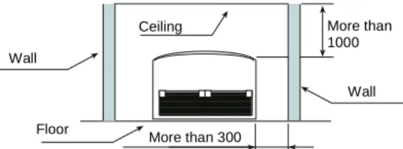
53.±:$//7<3(
&203$&7'(6,*1:,7+*5$&()8//,1(6 A conveniently slender design meas-uring a mere 380x215 mm, make these modules ideal for placement above doors or windows in restaurants, street front shops and wherever spaces is a premium.
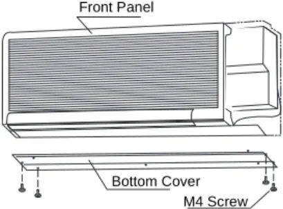
($6<&/($1$,5),/7(5
The air filter can be slid in or out in one simple motion encouraging for fresher, healthier air and more efficient and economical operation.
'5<23(5$7,21
The innovative dry operation mode enables you to feel cooler by lowering the humidity instead of the tempera-ture. A perfect choice for environments where temperature preferences vary. Dehumidified air leave everyone feel-ing refreshed.
48,(723(5$7,21
A smooth, well-contoured airflow tract and a sound-absorbing front air panel design dampen the operating sound from an already pleasantly quiet multi-blade fan system.
$8720$7,&6:,1*/289(56 Don’t let our attractive slim-line design deceive you... New Swing Louvers that automatically rotate in a continuous 80° cycle are teamed with an efficient and powerful centrifugal fan system to direct a comforting flow of air throughout your room
&RQFHDOHG
Rear Side
FEATURES 3
5$6287'22581,7
35(&+$5*('6<67(06
Perhaps our greatest contribution to easy and trouble-free installation pro-cedures has been the precharging of outdoor units with sufficient refrigerant to run a pipe length of almost 30 m. This highly refined and technologically improved HITACHI design means a radical savings in installation time and expense. Potential problems due to insufficient refrigerant are also effec-tively eliminated. No adjustments in the amount of refrigerant is necessary when the total pipe length is less than 30 m.
&$5()5((0$,17(1$1&(
Easy maintenance access is assured without the need to move or disconnect any of the outdoor units thanks to the conveniently located front access panel.
)/(;,%/(,167$//$7,21
New piping connectors pivot four-ways (front, read, side, underneath) to permit much easier access end freer positions of units. This greatly enhanced flexibil-ity reduces headaches at installation time and encourages the alignment of multiple outdoor units in more compact arrangements.
67521* '85$%/(6&52// &2035(66256
The Hitachi UTOPIA Series is equipped with the incomparably high performance Scroll-Type Compressor. This revolutionary breakthrough in compression technology allows simul-taneous intake and discharge of refrig-erant without the use of a single valve. The significant reduction of moving parts diminishes the incidence of wear and the subsequent need for servicing and part replacement; increases oper-ating efficiency through longer lived tune-ups and improved durability; less-ens noise and vibration; and contrib-utes to a significant decrease in overall operation costs and energy consump-tion.
(;7(1'('3,3,1*$//2:$1&(6
The maximum total piping length be-tween the standard outdoor compres-sor unit and all connected indoor units has been increased to 50 m (for 2 and 2.5HP units, the maximum total piping length is 30 m.) The greater lift allow-ance will now permit more flexible installation.
87,/,7$5,$163$&(6$9,1*'(6,*1 A sensibly located front access panel allows installation in a space-saving in-line configuration with as little as 50 mm separation between each unit-sharply contrasting with conventional side access units than must be posi-tioned several feet apart. Stop valve positioning and refrigerant piping al-lowances have also been improved to allow much more closely tailored posi-tioning of lines.
23(5$7,21$/72&
The outdoor heat pump air conditioning unit can be safely and effectively oper-ated in external temperatures as low as -10°C.
Outdoor Unit
Lift Between Indoor & Outdoor Unit, 30 m
Indoor Unit 50 m
GENERAL DATA 1
*(1(5$/'$7$
5&,&$66(77(7<3(
02'(/5&, 5&,+4( 5&,+4( 5&,+41(5&,+4( 5&,+4( 5&,+41(5&,+4( 5&,+41(5&,+4( 5&,+41(5&,+4(
Combined Outdoor Unit Model 5$6+49( 5$6+49(
5$6+4( 5$6+49(5$6+4( 5$6+4( 5$6+49(5$6+4( 5$6+4( 5$6+4( Nominal Cooling Capacity (*1) kcal/h W Btu/h 4 500 5 200 17 800 5 600 6 500 22 200 6 300 7 300 25 000 7 000 8 100 27 700 9 000 10 500 35 800 11 200 13 000 44 400 12 400 14 400 49 200 Nominal Cooling Capacity (*2) kcal/h W Btu/h 4 300 5 000 17100 5 400 6 300 21 500 6 100 7 100 24 300 6 800 7 900 27 000 8 800 10 200 34 800 11 000 12 800 43 700 12 200 14 200 48 500 Nominal Heating Capacity kcal/h W Btu/h
Air Flow Rate (Hi/Me/Lo) m3/min 15/13/10 18/15/12 21/18/15 23/20/16 32/28/24 34/29/25 37/32/27
Fan Motor W 30 30 30 30 60 60 80 Auxiliary Electric Heater at 220V or 415V at 380V kW kW – /2.1 – /1.8 – /3.1 – /2.6 – /3.1 – /2.6 – /3.1 – /2.6 Sound Pressure Level
(Overall A Scale) dB 36/34/32 38/37/35 41/38/35 42/39/36 44/41/37 45/41/37 46/42/38 mm 298 298 298 298 348 348 348 mm 820 820 820 820 1 140 1 140 1 140 Outer dimensions Height Width Depth mm 820 820 820 820 820 820 820 Net Weight kg 32 32 32/34 32 43/46 44/47 44/47
Refrigerant R-22 (Nitrogen Charged in Factory for Corrosion-Resistance) Flare-nut Connection (With Flare-Nuts)
PPLQ 6.35 (1/4) 9.53 (3/8) 9.53 (3/8) 9.53 (3/8) 9.53 (3/8) 9.53 (3/8) 9.53 (3/8) PPLQ 15.88 (5/8) 15.88 (5/8) 15.88 (5/8) 15.88 (5/8) 19.05 (3/4) 19.05 (3/4) 19.05 (3/4) Connections Refrigerant Piping Liquid Line Gas Line Condensate Drain VP25 VP25 VP25 VP25 VP25 VP25 VP25 Packing Measurements m3 0.37 0.37 0.37 0.37 0.55 0.55 0.55 Standard Accesories Remote Control Switch. Mounting Bracket
Adaptable Air Panel Model P-23W5(A)E(1) P-46W5(A)E(1) Color (Munsell Code) Silky White (2.5Y 8.9/1)
mm 120 120 120 120 120 120 120 mm 930 930 930 930 1 250 1 250 1 250 Outer Dimensions Height Width Depth mm 930 930 930 930 930 930 930 Net Weight kg 7 7 7 7 10 10 10 Packing Measurements m3 0.17 0.17 0.17 0.17 0.22 0.22 0.22 127(6
1. The nominal cooling and heating capacity is the combined capacity of the HITACHI standard split system, and are based on the ISO 5151.
Cooling Operation Conditions
Indoor Air Inlet Temperature: 27.0 °C DB
(*1) 19.5 °C WB
(*2) 19.0 °C WB
Outdoor Air Inlet Temperature: 35.0 °C DB Heating Operation Conditions
Indoor Air Inlet Temperature: 20.0 °C DB Outdoor Air Inlet Temperature: 7.0 °C DB 6.0 °C WB Piping Length: 7.5 meters
DB: Dry Bulb; WB: Wet Bulb
2. The nominal heating capacity for models 3HQN5E, RCI-4HQN5E, RCI-5HQN5E and RCI-6HQN5E includes auxiliary electric heaters.
3. The Sound Pressure Level is based on the following conditions: 1.5 meters Beneath the Unit
Voltage of the power source for the indoor fan motor is 220V. In case of the power source of 240V, the sound pressure level increases by about 1 dB.
The above data was measured in an anechoic chamber so that reflected sound should be taken into consideration when installing the unit.
4. Panels P46W5(A)E(1) or P23W5(A)E(1) are equipped with an automatic swing louver system.
$9$,/$%/(32:(56833/<92/7$*(6
The available voltages for the different units are shown in the following table
HITACHI Standard Split System
Power supply Model
Voltage (V) Phase Frequency (Hz)
RCI-2HQ5E RCI-2.5HQ5E RCI-3HQ5E RCI-3.5HQ5E RCI-4HQ5E RCI-5HQ5E RCI-6HQ5E 220-240 1 50 RCI-3HQN5E RCI-4HQN5E RCI-5HQN5E RCI-6HQN5E 220 380-415 3 50
2 GENERAL DATA
53,,17+(&(,/,1*7<3(
02'(/53, 53,+4( 53,+4( 53,+4( 53,+4( 53,+4( 53,+4( 53,+4(
Combined Outdoor Unit Model 5$6+49( 5$6+49(
5$6+4( 5$6+49(5$6+4( 5$6+4( 5$6+49(5$6+4( 5$6+4( 5$6+4( Nominal Cooling Capacity (*1) kcal/h W Btu/h 4 500 5 200 17 800 5 600 6 500 22 200 6 300 7 300 25 000 7 000 8 100 27 800 9 000 10 500 35 700 11 200 13 000 44 400 12 400 14 400 49 200 Nominal Cooling Capacity (*2) kcal/h W Btu/h 4 300 5 000 17100 5 400 6 300 21 500 6 100 7 100 24 200 6 800 7 900 27 000 8 800 10 200 34 800 11 000 12 800 43 700 12 200 14 200 48 500 Nominal Heating Capacity kcal/h W Btu/h 4 700 5 500 18 650 5 900 6 900 23 400 7 000 8 100 27 800 7 800 9 100 30 950 9 600 11 200 38 100 12 400 14 400 49 200 13 500 15 700 53 600 Air Flow Rate (Hi/Lo)
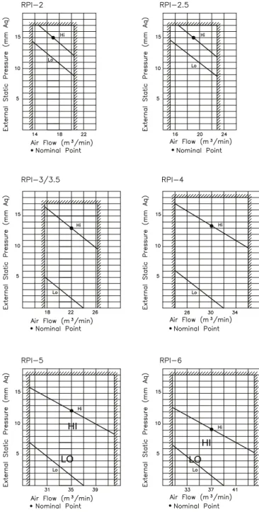
Nominal Air Flow External Static Pressure
m3/min mmAq 17/14 15/14 19/16 13/10 22 13/5 22 13/5 30 13.5/5 35 12/5 38/32 10/5 Fan Motor W 180 180 180 180 200 250 250
Sound Pressure Level
(Overall A Scale) dB 47/42 47/42 48 48 49 51 52/45 mm 278 278 278 278 278 278 278 mm 1170 1170 1170 1170 1560 1560 1 560 Outer dimensions Height Width Depth mm 609+40 609+40 609+40 609+40 609+40 609+40 609+40 Net Weight kg 44 46 46 46 55 56 56
Refrigerant R-22 (Nitrogen Charged in Factory for Corrosion-Resistance) Flare-nut Connection (With Flare-Nuts)
PPLQ 6.35 (1/4) 9.53 (3/8) 9.53 (3/8) 9.53 (3/8) 9.53 (3/8) 9.53 (3/8) 9.53 (3/8) PPLQ 15.88 (5/8) 15.88 (5/8) 15.88 (5/8) 15.88 (5/8) 19.05 (3/4) 19.05 (3/4) 19.05 (3/4) Connections Refrigerant Piping Liquid Line Gas Line Condensate Drain VP20 VP20 VP20 VP20 VP20 VP20 VP20 Packing Measurements m3 0.37 0.37 0.37 0.37 0.48 0.48 0.48
Standard Accesories Remote Control Switch
127(6
1. The nominal cooling and heating capacity is the combined capacity of the HITACHI standard split system, and are based on the ISO 13253.
Cooling Operation Conditions
Indoor Air Inlet Temperature: 27.0 °C DB (*1) 19.5 °C WB
(*2) 19.0 °C WB
Outdoor Air Inlet Temperature: 35.0 °C DB Heating Operation Conditions
Indoor Air Inlet Temperature: 20.0 °C DB Outdoor Air Inlet Temperature: 7.0 °C DB 6.0 °C WB Piping Length: 7.5 meters
DB: Dry Bulb; WB: Wet Bulb
2. The Sound Pressure Level is based on the following conditions: 1.5 meters from the unit side surface and 1 meter beneath the unit
Voltage of the power source for the indoor fan motor is 220V. In case of the power source of 240V, the sound pressure level increases by about 1 dB.
The above data was measured in an anechoic chamber so that reflected sound should be taken into consideration when installing the unit.
$9$,/$%/(32:(56833/<92/7$*(6
The available voltages for the different units are shown in the following table
HITACHI Standard Split System
Power supply Model
Voltage (V) Phase Frequency (Hz)
RPI-2HQ5E RPI-2.5HQ5E RPI-3HQ5E RPI-3.5HQ5E RPI-4HQ5E RPI-5HQ5E RPI-6HQ5E 220-240 1 50
GENERAL DATA 3
53&&(,/,1*7<3(
02'(/53& 53&+4( 53&+4( 53&+4(53&+41( 53&+4( 53&+4(53&+41( 53&+41(53&+4( 53&+41(53&+4(
Combined Outdoor Unit Model 5$6+49( 5$6+49(
5$6+4( 5$6+49(5$6+4( 5$6+4( 5$6+49(5$6+4( 5$6+4( 5$6+4( Nominal Cooling Capacity (*1) kcal/h W Btu/h 4 200 4 900 16 600 5 200 6 000 20 500 6 300 7 300 25 000 7 000 8 100 27 800 9 000 10 500 35 700 11 200 13 000 44 400 12 400 14 400 49 200 Nominal Cooling Capacity (*2) kcal/h W Btu/h 4 000 4 700 15800 5 000 5 800 19 800 6 100 7 100 24 200 6 800 7 900 27 000 8 800 10 200 34 900 11 000 12 800 43 600 12 200 14 200 48 500 Nominal Heating Capacity kcal/h W Btu/h
Air Flow Rate (Hi/Me/Lo) m3/min 15/13/10 18/16/12 21/17/15 23/20/16 30/24/19 35/28/21 37/32/27
Fan Motor W 65 65 65 65 150 180 180 Auxiliary Electric Heater at 220V or 415V at 380V kW kW – /2.1 – /1.8 – /3.1 – /2.6 – /3.1 – /2.6 – /3.1 – /2.6 Sound Pressure Level
(Overall A Scale) dB 46/44/40 48/45/41 48/45/41 48/45/41 49/44/41 49/46/41 52/48/44 mm 163 163 163 163 225 225 225 mm 1080 1 080 1 300 1 300 1 300 1 560 1 560 Outer dimensions Height Width Depth mm 625 625 625 625 625 625 625 Net Weight kg 28 28 31/34 35 35/38 41/44 41/44
Refrigerant R-22 (Nitrogen Charged in Factory for Corrosion-Resistance) Flare-nut Connection (With Flare-Nuts)
PPLQ 6.35 (1/4) 9.53 (3/8) 9.53 (3/8) 9.53 (3/8) 9.53 (3/8) 9.53 (3/8) 9.53 (3/8) PPLQ 15.88 (5/8) 15.88 (5/8) 15.88 (5/8) 15.88 (5/8) 19.05 (3/4) 19.05 (3/4) 19.05 (3/4) Connections Refrigerant Piping Liquid Line Gas Line Condensate Drain VP25 VP25 VP25 VP25 VP25 VP25 VP25 Packing Measurements m3 0.24 0.24 0.29 0.29 0.36 0.43 0.43 Standard Accesories Remote Control Switch. Mounting Bracket
127(6
1. The nominal cooling and heating capacity is the combined capacity of the HITACHI standard split system, and are based on the ISO 5151.
Cooling Operation Conditions
Indoor Air Inlet Temperature: 27.0 °C DB (*1) 19.5 °C WB
(*2) 19.0 °C WB
Outdoor Air Inlet Temperature: 35.0 °C DB Heating Operation Conditions
Indoor Air Inlet Temperature: 20.0 °C DB Outdoor Air Inlet Temperature: 7.0 °C DB 6.0 °C WB Piping Length: 7.5 meters
DB: Dry Bulb; WB: Wet Bulb
2. The Sound Pressure Level is based on the following conditions: 1 meter beneath the unit and 1 meter from Discharge Grille. Voltage of the power source for the indoor fan motor is 220V. In case of the power source of 240V, the sound pressure level increases by about 1 dB.
The above data was measured in an anechoic chamber so that reflected sound should be taken into consideration when installing the unit.
$9$,/$%/(32:(56833/<92/7$*(6
The available voltages for the different units are shown in the following table
HITACHI Standard Split System
Power supply Model
Voltage (V) Phase Frequency (Hz) RPC-3HQN5E RPC-4HQN5E RPC-5HQN5E RPC-6HQN5E 380-415 220 3 3 50 50 RPC-2HQ5E RPC-2.5HQ5E RPC-3HQ5E RPC-3.5HQ5E RPC-4HQ5E RPC-5HQ5E RPC-6HQ5E 220-240 1 50
4 GENERAL DATA
53))/2257<3(
02'(/53) 53)+4( 53)+4( 53)+4(
Combined Outdoor Unit Model 5$6+49( 5$6+49(
5$6+4( 5$6+49(5$6+4( Nominal Cooling Capacity (*1) kcal/h W Btu/h 4 200 4 900 16 600 5 200 6 000 20 500 6 300 7 300 25 000 Nominal Cooling Capacity (*2) kcal/h W Btu/h 4 000 4 700 15800 5 000 5 800 19 800 6 100 7 100 24 200 Nominal Heating Capacity kcal/h W Btu/h 4 300 5 000 18 600 5 400 6 300 21 500 7 000 8 100 27 800 Air Flow Rate (Hi/Me/Lo) m3/min 15/13/10 18/16/12 21/17/14
Fan Motor W 65 65 65
Sound Pressure Level
(Overall A Scale) dB 46/44/40 48/45/41 48/45/41 mm 625 625 625 mm 1 080 1 080 1 300 Outer dimensions Height Width Depth mm 163 163 163 Net Weight kg 28 28 31
Refrigerant R-22 (Nitrogen Charged in Factory for Corrosion-Resistance) Flare-nut Connection (With Flare-Nuts)
PPLQ 6.35 (1/4) 9.53 (3/8) 9.53 (3/8) PPLQ 15.88 (5/8) 15.88 (5/8) 15.88 (5/8) Connections Refrigerant Piping Liquid Line Gas Line Condensate Drain VP20 VP20 VP20 Packing Measurements m3 0.24 0.24 0.29
Standard Accesories Remote Control Switch. Mounting Bracket
127(6
1. The nominal cooling and heating capacity is the combined capacity of the HITACHI standard split system, and are based on the ISO 5151.
Cooling Operation Conditions
Indoor Air Inlet Temperature: 27.0 °C DB (*1) 19.5 °C WB
(*2) 19.0 °C WB
Outdoor Air Inlet Temperature: 35.0 °C DB Heating Operation Conditions
Indoor Air Inlet Temperature: 20.0 °C DB Outdoor Air Inlet Temperature: 7.0 °C DB 6.0 °C WB Piping Length: 7.5 meters
DB: Dry Bulb; WB: Wet Bulb
2. The Sound Pressure Level is based on the following conditions: 1 meter beneath the unit and 1 meter from Floor Level. Voltage of the power source for the indoor fan motor is 220V. In case of the power source of 240V, the sound pressure level increases by about 1 dB.
The above data was measured in an anechoic chamber so that reflected sound should be taken into consideration when installing the unit.
$9$,/$%/(32:(56833/<92/7$*(6
The available voltages for the different units are shown in the following table
HITACHI Standard Split System
Power supply Model
Voltage (V) Phase Frequency (Hz) RPF-2HQ5E
RPF-2.5HQ5E RPF-3HQ5E
GENERAL DATA 5
53.:$//7<3(
02'(/53. 53.+4 53.+4
Combined Outdoor Unit Model 5$6+49(
5$6+4( 5$6+49(5$6+4( Nominal Cooling Capacity (*1) kcal/h W Btu/h 6 300 7 300 25 000 8 800 10 200 34 900 Nominal Cooling Capacity (*2) kcal/h W Btu/h 6 100 7 100 24 200 8 500 9 880 33 700 Nominal Heating Capacity kcal/h W Btu/h 7 000 8 100 27 800 9 600 11 200 38 100 Air Flow Rate (Hi/Lo) m3/min 22/18/15 28/24/20
Fan Motor W 30 60
Sound Pressure Level
(Overalll A Scale) dB 44/41/38 50/45/42 Outer dimensions Height mm 380 380 Width mm 1 500 1 500 Depth mm 215 215 Net Weight kg 27 30
Refrigerant R-22 (Nitrogen Charged in Factory for Corrosion-Resistance Connections
Refrigerant Piping Flare-nut Connection (With Flare-Nuts) Liquid Line PPLQ 9.53 (3/8) 9.53 (3/8) Gas Line PPLQ 15.88 (5/8) 19.5 (3/4)
Condensate Drain VP20 VP20
Approximate Packing Measurements m3 0.37 0.25 Standard Accesories 5HPRWH&RQWURO6ZLWFK:DOO0RXQWLQJ%UDFNHW
127(6
1. The nominal cooling and heating capacity is the combined capacity of the HITACHI standard split system, and are based on the ISO 5151.
Cooling Operation Conditions
Indoor Air Inlet Temperature: 27.0 °C DB (*1) 19.5 °C WB
(*2) 19.0 °C WB
Outdoor Air Inlet Temperature: 35.0 °C DB Heating Operation Conditions
Indoor Air Inlet Temperature: 20.0 °C DB Outdoor Air Inlet Temperature: 7.0 °C DB 6.0 °C WB Piping Length: 7.5 meters
DB: Dry Bulb; WB: Wet Bulb
2. The Sound Pressure Level is based on the following conditions: 1 meter from the unit side surface.
Voltage of the power source for the indoor fan motor is 220V. In case of the power source of 240V, the sound pressure level increases by about 1 dB.
The above data was measured in an anechoic chamber so that reflected sound should be taken into consideration when installing the unit.
$9$,/$%/(32:(56833/<92/7$*(6
The available voltages for the different units are shown in the following table
HITACHI Standard Split System
Power supply Model
Voltage (V) Phase Frequency (Hz) RPK-3HQ5
6 GENERAL DATA
5$6287'22581,7
02'(/5$6 5$6+49( 5$6+4(5$6+49( 5$6+49(5$6+4( 5$6+4( 5$6+49(5$6+4( 5$6+4( 5$6+4(
Cabinet Color
(Munsell Code) Synthetic Resin Paint Baked on Galvanized Steel Plate Beige (2.5Y 8/2) Sound Pressure Level
(Overall A Scale) dB 49 51 52 53 53 54 55 mm 735 735 885 885 1 135 1 135 1 135 mm 890 890 890 890 890 1060 1060 Outer Dimensions Height Width Depht mm 285 285 285 285 285 345 345 Net Weight kg 60 63 70 79 94 110 103
Refrigerant R22 (Factory Charged)
Compressor Hermetic (Scroll)
Model Quantity 200 AH 1 250 AH 1 300 AH 1 350 DH 1 400 DH 1 500 DH 1 600 DH 1
Fan Motor Propeller Fan
Output Quantity W 70 1 70 1 70 1 70 1 70+70 2 70+70 2 70+70 2
Connections Flare-Nut Connection (With Flare Nuts)
Refrigerant Piping Liquid Line Gas Line mm (in.) mm (in.) Packing Measurements m3 0.24 0.24 0.46 0.46 0.56 0.74 0.74 127(6
1. The Sound Pressure Level is based on the following conditions: 1 meter from the unit front surface and 1.5 meter from floor level. In case of the power source of 240V, the sound pressure level increases by about 1 dB.
The above data was measured in an anechoic chamber so that reflected sound should be taken into consideration when installing the unit.
2. The outdoor unit is charged with refrigerant before shipment. The charged volume is the equivalent of a refrigerant piping length of 30 meters, (10 meters for RAS-2 and RAS-2.5 ) when combining the HITACHI standard indoor unit.
$9$,/$%/(32:(56833/<92/7$*(6
The available voltages for the different units are shown in the following table.
HITACHI Standard Power supply
Power Supply Model
Voltage (V) Phase Frequency (Hz)
RAS-2.5HQE5 RAS-3HQE5 RAS-3.5HQE5 RAS-4HQE5 RAS-5HQE5 RAS-6HQE5 220 380-415 3 50 RAS-2HQVE5 RAS-2.5HQVE5 RAS-3HQVE5 RAS-4HQVE5 220-240 1 50
GENERAL DATA 7
&20321(176'(7$,/(''$7$
&RPSUHVVRU
0RGHO units $+ $+ $+ '+ '+ '+ '+
Compressor type Hermetic scroll
Revolution 50 Hz rpm 2 880 2 880 2 880 2 880 2 880 2 880 2 880 Displacement 50 Hz m3/h 4.10 6.48 8.12 9.68 11.09 13.82 15.55
Capacity Steps % 0-100 0-100 0-100 0-100 0-100 0-100 0-100 Air Tight Pressure
Discharge NJFP* N3D 3 04030.0 30.0 3 040 30.0 3 040 30.0 3040 30.0 3 040 30.0 3 040 30.0 3 040
Motor Type Special Cage Motor
Starting Method Direct-on-Line Starting (Three Phase) Permanent Split Starting Capacitor (Single Phase)
Poles 2 2 2 2 2 2 2
Insulation E E E E E E E
Oil Type FREOL F56
Charge liters 1.0 1.0 1.0 1.2 1.5 1.8 1.8
5&,,QGRRU+HDW([FKDQJHUDQG)DQ8QLW
0RGHO
units
5&,+4( 5&,+4( 5&,+41( 5&,+4(5&,+4( 5&,+41(5&,+4( 5&,+41(5&,+4( 5&,+41(5&,+4(
Heat Exchanger Type Multi-Pass Cross Finned Tube
Material Copper Tube
Outer Diameter PPLQ Tube Rows 1 2 2 2 2 2 2 Material Aluminium Fin Pitch mm 2 2 2 2 2 2 2
Maximum Operating Pressure NJFP*
N3D 3 04030.0 30.0 3 040 30.0 3 040 30.0 3 040 30.0 3 040 30.0 3 040 30.0 3 040
Number of Heat Exchanger/Unit 1 1 1 1 1 1 1
Direct Driven Turbo Fan
Number/unit 1 1 1 1 1 1 1
Outer Diameter PP 400 400 400 400 450 450 450
Fan
Nominal Air Flow (H/M/L) PPLQ
Fan Motor Drip-proof Type Enclosure
Starting method Permanent Split Capacitor
Nominal Output : 30 30 30 30 60 60 80
Quantity 1 1 1 1 1 1 1
Insulation Class B B B B B B B
53,,QGRRU+HDW([FKDQJHUDQG)DQ8QLW
0RGHO units 53,+4( 53,+4( 53,+4( 53,+4( 53,+4( 53,+4( 53,+4(
Heat Exchanger Type Multi-Pass Cross Finned Tube
Material Cooper Tube
Outer Diameter PPLQ Tube Rows 2 3 3 3 3 3 3 Material Aluminium Fin Pitch mm 2 2 2 2 2 2 2
Maximum Operating Pressure NJFP*
N3D 3 04030.0 30.0 3 040 30.0 3 040 30.0 3 040 30.0 3 040 30.0 3 040 30.0 3 040
Number of Heat Exchanger/Unit 1 1 1 1 1 1 1
Direct Driven Centrifugal Fan
Number/unit 2 2 2 2 2 2 2
Outer Diameter PP 180 180 180 180 180 180 180
Fan
Nominal Air Flow (H/L) PPLQ 17/14 19/16 22 22 30 35 38/32
Fan Motor Drip-proof Type Enclosure
Starting method Permanent Split Capacitor
Nominal Output : 180 180 180 180 200 250 270
Quantity 1 1 1 1 1 1 1
8 GENERAL DATA
53&,QGRRU+HDW([FKDQJHUDQG)DQ8QLW
0RGHO units 53&+4( 53&+4( 53&+4(53&+41( 53&+4( 53&+4(53&+41( 53&+41(53&+4( 53&+41(53&+4(
Heat Exchanger Type Multi-Pass Cross Finned Tube
Material Cooper Tube
Outer Diameter PPLQ Tube Rows 3 3 3 3 3 3 3 Material Aluminium Fin Pitch mm 2 2 2 2 2 2 2
Maximum Operating Pressure NJFP*
N3D 3 04030.0 30.0 3 040 30.0 3 040 30.0 3 040 30.0 3 040 30.0 3 040 30.0 3 040
Number of Heat Exchanger/Unit 1 1 1 1 1 1 1
Direct Driven Centrifugal Fan
Number/unit 3 3 4 4 3 4 4
Outer Diameter PP 101 101 101 101 136 136 136
Fan
Nominal Air Flow (H/M/L) PPLQ
Fan Motor Drip-proof Type Enclosure
Starting method Permanent Split Capacitor
Nominal Output : 65 65 65 65 150 180 195
Quantity 1 1 1 1 1 1 1
Insulation Class B B B B B B B
53)DQG53.,QGRRU+HDW([FKDQJHUDQG)DQ8QLW
0RGHOV units 53)+4( 53)+4( 53)+4( 53.+4 53.+4
Heat Exchanger Type Multi-Pass Cross Finned Tube
Material Cooper Tube
Outer Diameter PPLQ Tube Rows 3 3 3 2 2 Material Aluminium Fin Pitch mm 2 2 2 2 2
Maximum Operating Pressure NJFP*
N3D 3 04030.0 30.0 3 040 30.0 3 040 30.0 3 040 30.0 3 040
Number of Heat Exchanger/Unit 1 1 1 1 1
'LUHFW'ULYHQ&HQWULIXJDO)DQ 'LUHFW'ULYHQ7DQJHQFLDO)DQ
Number/unit 3 3 4 1 1
Outer Diameter PP 101 101 101 130 130
Fan
Nominal Air Flow (H/M/L) PPLQ
Fan Motor Drip-proof Type Enclosure
Starting method Permanent Split Capacitor
Nominal Output : 65 65 65 30 60
Quantity 1 1 1 1 1
Insulation Class B B B E E
2XWGRRU+HDW([FKDQJHU
0RGHO 5$6+49( 5$6+4(5$6+49( 5$6+49(5$6+4( 5$6+4( 5$6+4(5$6+49( 5$6+4( 5$6+4(
Heat Exchanger Type Multi-Pass Cross Finned Tube
Tube Material Cooper Tube
Outer Diameter mm 9.53 9.53 9.53 9.53 9.53 9.53 9.53
Rows 2 2 2 2 2 2 2
Fin Material Aluminium
Pitch mm 2 2 2 2 2 2 2
Maximum Operating Pressure NJFP*
N3D 3 04030.0 30.0 3 040 30.0 3 040 30.0 3 040 30.0 3 040 30.0 3 040 30.0 3 040
Number of Heat Exchanger/Unit 1 1 1 1 1 1 1
Fan Direct Driver Propeller Fan
Number/Unit 1 1 1 1 2 2 2
Outer Diameter mm 440 440 440 440 440 440 440
Revolution rpm 840 840 860 860 1 050 780/850 800/870
Nominal Air Flow/Fan PPLQ 40 40 46 46 60 92 96
Fan Motor Drip-Proof Type Enclosure
Starting Method Permanent Split Capacitor
Nominal Output W 70 70 70 70 70+70 70+70 70+70
Quantity 1 1 1 1 2 2 2
',0(16,21$/'$7$
,1'22581,7±5&,&$66(77(7<3(
5&,+4(5&,+4(5&,+4(5&,+41(5&,+4( XEKS0007 5&,+4(5&,+41(5&,+4(5&,+41(5&,+4(5&,+41( XEKS0028 Unit: mm Unit: mm,1'22581,753,,17+(&(,/,1*7<3(
53,+4(53,+4(53,+4(53,+4( 53,+4(53,+4(53,+4( Unit: mm Unit: mm XEKS0084 XEKS0085,1'22581,753&&(,/,1*7<3(
53&+4(53&+4( 53&+4(53&+41(53&+4( Unit: mm Unit: mm XEKS0037 XEKS0041,1'22581,753))/2257<3(
53)+4(53)+4( 53)+4( Unit: mm Unit: mm XEKS0086 XEKS00886 DIMENSIONAL DATA
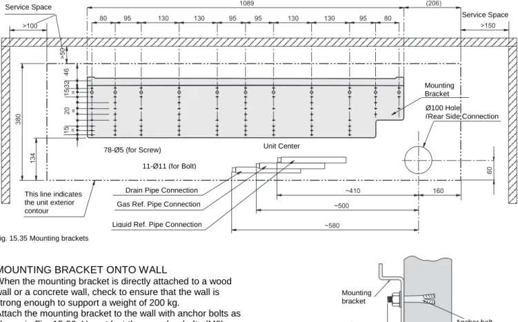
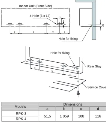
,1'22581,753.:$//7<3(
53.+453.+4287'22581,75$6
5$6+49(5$6+4(5$6+49( 5$6+4(5$6+49(5$6+4( Unit: mm Unit: mm XEKS0033 XEKS0005&22/,1*$1'+($7,1*&$3$&,7,(6
&22/,1*&$3$&,7<7$%/(6
5&,&$66(77(7<3(&22/,1*23(5$7,21
,QGRRU8QLW,QOHW$LU 2XWGRRU8QLW,QOHW$LU'5<%8/%7HPSHUDWXUH& & 0RGHOV 8QLWV 4$&5 :% '% 7& 6+& &,37 ,37 ((5 7& 6+& &,37 ,37 ((5 7& 6+& &,37 ,37 ((5 7& 6+& &,37 ,37 ((5 7& 6+& &,37 ,37 ((5
5&,+4( 5$6+49( +3 +] a 5&,+4( 5$6+4( +3 +] a 5&,+4( 5$6+49( +3 +] a 5&,+41( 5$6+4( +3 +] a 5&,+4( 5$6+49( +3 +] a 5&,+4( 5$6+4( +3 +] a 5&,+41( 5$6+4( +3 +] a 5&,+4( 5$6+49( +3 +] a 5&,+41( 5$6+4( +3 +] a 5&,+41( 5$6+4( +3 +] a &RUUHFWLRQIDFWRUIRU&RROLQJ&DSDFLW\DQG&RPSUHVVRU,QSXWGXHWR$LU)ORZUDWH 0RGHO 4$ )RU7& )RU&,37
Lo 10 0.94 0.95 Me 13 0.97 0.98 2 HP Hi 15 1.00 1.00 Lo 12 0.94 0.95 Me 15 0.97 0.98 2.5 HP Hi 18 1.00 1.00 Lo 15 0.95 0.98 Me 18 0.95 0.99 3 HP Hi 21 1.00 1.00 Lo 16 0.93 0.97 Me 20 0.95 0.99 3.5 HP Hi 23 1.00 1.00 Lo 24 0.92 0.97 Me 28 0.96 0.99 4 HP Hi 32 1.00 1.00 Lo 25 0.91 0.96 Me 29 0.95 0.99 5 HP Hi 34 1.00 1.00 Lo 27 0.90 0.95 Me 32 0.95 0.99 6 HP Hi 37 1.00 1.00
QA: Indoor Unit Air Flow (m3/min) CR: Sensible Heat Correction Factor WB: Evaporator Air Inlet Wet Bulb (°C) DB: Evaporator Air Inlet Dry Bulb (°C) TC: Total Cooling Capacity (kW)
SHC: Sensible Heat Capacity (kW) given for each WB and DB CIPT: Compressor Input Power (kW)
IPT: Total Input Power (including fans) (kW) EER: TC/IPT
SHCc=SHC+CR(DBr-DB)
DBr: Real Indoor Unit Air Inlet Dry Bulb(°C)
SHCc: Corrected Sensible Heat Capacity (kW), at certain DBr
1RWH ,QWKHFDVHRIWZLQFRQQHFWLRQUHIHUWRWKHWDEXODWHGVLQJOHV\VWHP ZKLFKXVHVWKHVDPHRXWGRRUXQLW
2 COOLING AND HEATING CAPACITIES
53,,17+(&(,/,1*7<3(&22/,1*23(5$7,21
,QGRRU8QLW,QOHW$LU 2XWGRRU8QLW,QOHW$LU'5<%8/%7HPSHUDWXUH&
&
0RGHOV 8QLWV 4$
&5 :% '% 7& 6+& &,37 ,37 ((5 7& 6+& &,37 ,37 ((5 7& 6+& &,37 ,37 ((5 7& 6+& &,37 ,37 ((5 7& 6+& &,37 ,37 ((5
53,+4( 5$6+49( +3 +] a 53,+4( 5$6+4( +3 +] a 53,+4( 5$6+49( +3 +] a 53,+4( 5$6+4( +3 +] a 53,+4( 5$6+49( +3 +] a 53,+4( 5$6+4( +3 +] a 53,+4( 5$6+4( +3 +] a 53,+4( 5$6+49( +3 +] a 53,+4( 5$6+4( +3 +] a 53,+4( 5$6+4( +3 +] a &RUUHFWLRQIDFWRUIRU&RROLQJ&DSDFLW\DQG&RPSUHVVRU,QSXWGXHWR$LU)ORZUDWH 0RGHO 4$ )RU7& )RU&,37
Lo 14 0.94 0.95 Me 17 1.00 1.00 2 HP Hi 17 1.00 1.00 Lo 16 0.94 0.95 Me 19 1.00 1.00 2.5 HP Hi 19 1.00 1.00 Lo 14 0.88 0.93 Me 21 1.00 1.00 3 HP Hi 21 1.00 1.00 Lo 16 0.88 0.93 Me 23 1.00 1.00 3.5 HP Hi 23 1.00 1.00 Lo 19 0.88 0.93 Me 30 1.00 1.00 4 HP Hi 30 1.00 1.00 Lo 21 0.87 0.92 Me 35 1.00 1.00 5 HP Hi 35 1.00 1.00 Lo 32 0.94 0.98 Me 38 1.00 1.00 6 HP Hi 38 1.00 1.00
QA: Indoor Unit Air Flow (m3/min) CR: Sensible Heat Correction Factor WB: Evaporator Air Inlet Wet Bulb (°C) DB: Evaporator Air Inlet Dry Bulb (°C) TC: Total Cooling Capacity (kW)
SHC: Sensible Heat Capacity (kW) given for each WB and DB CIPT: Compressor Input Power (kW)
IPT: Total Input Power (including fans) (kW) EER: TC/IPT
SHCc=SHC+CR(DBr-DB)
DBr: Real Indoor Unit Air Inlet Dry Bulb(°C)
SHCc: Corrected Sensible Heat Capacity (kW), at certain DBr
1RWH ,QWKHFDVHRIWZLQFRQQHFWLRQUHIHUWRWKHWDEXODWHGVLQJOHV\VWHP ZKLFKXVHVWKHVDPHRXWGRRUXQLW
53&&(,/,1*7<3(&22/,1*23(5$7,21
,QGRRU8QLW,QOHW$LU 2XWGRRU8QLW,QOHW$LU'5<%8/%7HPSHUDWXUH&
&
0RGHOV 8QLWV 4$
&5 :% '% 7& 6+& &,37 ,37 ((5 7& 6+& &,37 ,37 ((5 7& 6+& &,37 ,37 ((5 7& 6+& &,37 ,37 ((5 7& 6+& &,37 ,37 ((5
53&+4( 5$6+49( +3 +] a 53&+4( 5$6+4( +3 +] a 5&,+4( 5$6+49( +3 +] a 53&+41( 5$6+4( +3 +] a 53&+4( 5$6+49( +3 +] a 53&+4( 5$6+4( +3 +] a 53&+41( 5$6+4( +3 +] a 53&+4( 5$6+49( +3 +] a 53&+41( 5$6+4( +3 +] a 53&+41( 5$6+4( +3 +] a &RUUHFWLRQIDFWRUIRU&RROLQJ&DSDFLW\DQG&RPSUHVVRU,QSXWGXHWR$LU)ORZUDWH 0RGHO 4$ )RU7& )RU&,37
Lo 10 0.94 0.95 Me 13 0.97 0.98 2 HP Hi 15 1.00 1.00 Lo 12 0.94 0.95 Me 15 0.97 0.98 2.5 HP Hi 18 1.00 1.00 Lo 15 0.89 0.94 Me 18 0.94 0.98 3 HP Hi 21 1.00 1.00 Lo 16 0.89 0.93 Me 20 0.94 0.98 3.5 HP Hi 23 1.00 1.00 Lo 24 0.88 0.93 Me 28 0.93 0.98 4 HP Hi 32 1.00 1.00 Lo 25 0.87 0.92 Me 29 0.93 0.98 5 HP Hi 34 1.00 1.00 Lo 27 0.85 0.93 Me 32 0.91 0.98 6 HP Hi 37 1.00 1.00
QA: Indoor Unit Air Flow (m3/min)
CR: Sensible Heat Correction Factor WB: Evaporator Air Inlet Wet Bulb (°C) DB: Evaporator Air Inlet Dry Bulb (°C) TC: Total Cooling Capacity (kW)
SHC: Sensible Heat Capacity (kW) given for each WB and DB CIPT: Compressor Input Power (kW)
IPT: Total Input Power (including fans) (kW) EER: TC/IPT
SHCc=SHC+CR(DBr-DB)
DBr: Real Indoor Unit Air Inlet Dry Bulb(°C)
SHCc: Corrected Sensible Heat Capacity (kW), at certain DBr
1RWH ,QWKHFDVHRIWZLQFRQQHFWLRQUHIHUWRWKHWDEXODWHGVLQJOHV\VWHP ZKLFKXVHVWKHVDPHRXWGRRUXQLW
4 COOLING AND HEATING CAPACITIES
53))/2257<3(&22/,1*23(5$7,21
,QGRRU8QLW,QOHW$LU 2XWGRRU8QLW,QOHW$LU'5<%8/%7HPSHUDWXUH&
&
0RGHOV 8QLWV 4$
&5 :% '% 7& 6+& &,37 ,37 ((5 7& 6+& &,37 ,37 ((5 7& 6+& &,37 ,37 ((5 7& 6+& &,37 ,37 ((5 7& 6+& &,37 ,37 ((5
53)+4( 5$6+49( +3 +] a 53)+4( 5$6+4( +3 +] a 53)+4( 5$6+49( +3 +] a 53)+4( 5$6+4( +3 +] a 53)+4( 5$6+49( +3 +] a &RUUHFWLRQIDFWRUIRU&RROLQJ&DSDFLW\DQG&RPSUHVVRU,QSXWGXHWR$LU)ORZUDWH 0RGHO 4$ )RU7& )RU&,37
Lo 10 0.94 0.95 Me 13 0.97 0.98 2 HP Hi 15 1.00 1.00 Lo 12 0.94 0.95 Me 15 0.97 0.98 2.5 HP Hi 18 1.00 1.00 Lo 15 0.89 0.94 Me 18 0.94 0.98 3 HP Hi 21 1.00 1.00
QA: Indoor Unit Air Flow (m3/min) CR: Sensible Heat Correction Factor WB: Evaporator Air Inlet Wet Bulb (°C) DB: Evaporator Air Inlet Dry Bulb (°C) TC: Total Cooling Capacity (kW)
SHC: Sensible Heat Capacity (kW) given for each WB and DB CIPT: Compressor Input Power (kW)
IPT: Total Input Power (including fans) (kW) EER: TC/IPT
SHCc=SHC+CR(DBr-DB)
DBr: Real Indoor Unit Air Inlet Dry Bulb(°C)
SHCc: Corrected Sensible Heat Capacity (kW), at certain DBr
53.:$//7<3(&22/,1*23(5$7,21
,QGRRU8QLW,QOHW$LU 2XWGRRU8QLW,QOHW$LU'5<%8/%7HPSHUDWXUH&
&
0RGHOV 8QLWV 4$
&5 :% '% 7& 6+& &,37 ,37 ((5 7& 6+& &,37 ,37 ((5 7& 6+& &,37 ,37 ((5 7& 6+& &,37 ,37 ((5 7& 6+& &,37 ,37 ((5
53.+4( 5$6+4( +3 +] a 53.+4( 5$6+49( +3 +] a 53.+4( 5$6+4( +3 +] a $ 53.+4( 5$6+49( +3 +] a &RUUHFWLRQIDFWRUIRU&RROLQJ&DSDFLW\DQG&RPSUHVVRU,QSXWGXHWR$LU)ORZUDWH 0RGHO 4$ )RU7& )RU&,37
Lo 15 0.89 0.95 Me 18 0.94 0.98 3 HP Hi 22 1.00 1.00 Lo 20 0.90 0.96 Me 24 0.95 0.99 4 HP Hi 28 1.00 1.00
QA: Indoor Unit Air Flow (m3/min)
CR: Sensible Heat Correction Factor WB: Evaporator Air Inlet Wet Bulb (°C) DB: Evaporator Air Inlet Dry Bulb (°C) TC: Total Cooling Capacity (kW)
SHC: Sensible Heat Capacity (kW) given for each WB and DB CIPT: Compressor Input Power (kW)
IPT: Total Input Power (including fans) (kW) EER: TC/IPT
SHCc=SHC+CR(DBr-DB)
DBr: Real Indoor Unit Air Inlet Dry Bulb(°C)
+($7,1*&$3$&,7<7$%/(6
5&,&$66(77(7<3(+($7,1*23(5$7,21
,QGRRU8QLW,QOHW$LU 2XWGRRU8QLW,QOHW$LU:(7%8/%7HPSHUDWXUH&
&
0RGHOV 8QLW 4$
:% '% 7+ &,37 ,37 &23 7+ &,37 ,37 &23 7+ &,37 ,37 &23 7+ &,37 ,37 &23 7+ &,37 ,37 &23 7+ &,37 ,37 &23
5&,+4( 5$6+49( +3 +] a 5&,+4( 5$6+4( +3 +] a 5&,+4( 5$6+49( +3 +] a 5&,+41( 5$6+4( +3 +] a 5&,+4( 5$6+49( +3 +] a 5&,+4( 5$6+4( +3 +] a 5&,+41( 5$6+4( +3 +] a 5&,+4( 5$6+49( +3 +] a 5&,+41( 5$6+4( +3 +] a 5&,+41( 5$6+4( +3 +] a &RUUHFWLRQIDFWRUIRU+HDWLQJ&DSDFLW\GXHWR$LU)ORZUDWH 0RGHO 4$ IRU7& 0RGHO 4$ IRU7&
Lo 10 0.94 Lo 24 0.96 Me 13 0.97 Me 28 0.98 2 HP Hi 15 1.00 4 HP Hi 32 1.00 Lo 12 0.95 Lo 25 0.97 Me 15 0.98 Me 29 0.99 2.5 HP Hi 18 1.00 5 HP Hi 34 1.00 Lo 15 0.95 Lo 27 0.97 Me 18 0.98 Me 32 0.99 3 HP Hi 21 1.00 6 HP Hi 37 1.00 Lo 16 0.96 Me 20 0.98 3.5 HP Hi 23 1.00
QA: Indoor Unit Air Flow (m3/min) DB: Evaporator Air Inlet Dry Bulb (°C) TH: Total Heating Capacity (kW) CIPT: Compressor Input Power (kW) IPT: Total Input Power (including fans) (kW) COP: TH/IPT
1RWH )RUWKHDERYHGDWDWKHHOHFWULFKHDWHULVFRQVLGHUHGWREH 2))LQWKHFDVHRI1W\SHPRGHOV5HIHUWRHOHFWULFDOGDWD 1RWH ,QWKHFDVHRIWZLQFRQQHFWLRQUHIHUWRWKHWDEXODWHGVLQJOH
6 COOLING AND HEATING CAPACITIES
53,,17+(&(,/,1*7<3(+($7,1*23(5$7,21
,QGRRU8QLW,QOHW$LU 2XWGRRU8QLW,QOHW$LU:(7%8/%7HPSHUDWXUH&
&
0RGHOV 8QLW
4$ :% '% 7+ &,37 ,37 &23 7+ &,37 ,37 &23 7+ &,37 ,37 &23 7+ &,37 ,37 &23 7+ &,37 ,37 &23 7+ &,37 ,37 &23
53,+4( 5$6+49( +3 +] a 53,+4( 5$6+4( +3 +] a 53,+4( 5$6+49( +3 +] a 53,+4( 5$6+4( +3 +] a 53,+4( 5$6+49( +3 +] a 53,+4( 5$6+4( +3 +] a 53,+4( 5$6+4( +3 +] a 53,+4( 5$6+49( +3 +] a 53,+4( 5$6+4( +3 +] a 53,+4( 5$6+4( +3 +] a &RUUHFWLRQIDFWRUIRU+HDWLQJ&DSDFLW\GXHWR$LU)ORZUDWH 0RGHO 4$ IRU7& 0RGHO 4$ IRU7&
Lo 14 0.94 Lo 0.96 Me 17 1.00 Me 30 1.00 2 HP Hi 17 1.00 4 HP Hi 30 1.00 Lo 16 0.95 Lo 0.97 Me 19 1.00 Me 35 1.00 2.5 HP Hi 19 1.00 5 HP Hi 35 1.00 Lo 0.95 Lo 0.97 Me 22 1.00 Me 38 1.00 3 HP Hi 22 1.00 6 HP Hi 38 1.00 Lo 0.96 Me 23 1.00 3.5 HP Hi 23 1.00
QA: Indoor Unit Air Flow (m3/min)
DB: Evaporator Air Inlet Dry Bulb (°C) TH: Total Heating Capacity (kW) CIPT: Compressor Input Power (kW) IPT: Total Input Power (including fans) (kW) COP: TH/IPT
1RWH ,QWKHFDVHRIWZLQFRQQHFWLRQUHIHUWRWKHWDEXODWHGVLQJOH V\VWHPZKLFKXVHVWKHVDPHRXWGRRUXQLW
53&&(,/,1*7<3(+($7,1*23(5$7,21
,QGRRU8QLW,QOHW$LU 2XWGRRU8QLW,QOHW$LU:(7%8/%7HPSHUDWXUH&
&
0RGHOV 8QLW
4$ :% '% 7+ &,37 ,37 &23 7+ &,37 ,37 &23 7+ &,37 ,37 &23 7+ &,37 ,37 &23 7+ &,37 ,37 &23 7+ &,37 ,37 &23
53&+4( 5$6+49( +3 +] a 53&+4( 5$6+4( +3 +] a 53&+4( 5$6+49( +3 +] a 53&+41( 5$6+4( +3 +] a 53&+4( 5$6+49( +3 +] a 53&+4( 5$6+4( +3 +] a 53&+41( 5$6+4( +3 +] a 53&+4( 5$6+49( +3 +] a 53&+41( 5$6+4( +3 +] a 53&+41( 5$6+4( +3 +] a &RUUHFWLRQIDFWRUIRU+HDWLQJ&DSDFLW\GXHWR$LU)ORZUDWH 0RGHO 4$ IRU7& 0RGHO 4$ IRU7&
Lo 10 0.94 Lo 24 0.96 Me 13 0.97 Me 28 0.98 2 HP Hi 15 1.00 4 HP Hi 32 1.00 Lo 12 0.95 Lo 25 0.97 Me 15 0.98 Me 29 0.99 2.5 HP Hi 18 1.00 5 HP Hi 34 1.00 Lo 15 0.95 Lo 27 0.97 Me 18 0.98 Me 32 0.99 3 HP Hi 21 1.00 6 HP Hi 37 1.00 Lo 16 0.96 Me 20 0.98 3.5 HP Hi 23 1.00
QA: Indoor Unit Air Flow (m3/min)
DB: Evaporator Air Inlet Dry Bulb (°C) TH: Total Heating Capacity (kW) CIPT: Compressor Input Power (kW) IPT: Total Input Power (including fans) (kW) COP: TH/IPT
1RWH )RUWKHDERYHGDWDWKHHOHFWULFKHDWHULVFRQVLGHUHGWREH 2))LQWKHFDVHRI1W\SHPRGHOV5HIHUWRHOHFWULFDOGDWD 1RWH ,QWKHFDVHRIWZLQFRQQHFWLRQUHIHUWRWKHWDEXODWHGVLQJOH
8 COOLING AND HEATING CAPACITIES
53))/2257<3(+($7,1*23(5$7,21
,QGRRU8QLW,QOHW$LU 2XWGRRU8QLW,QOHW$LU:(7%8/%7HPSHUDWXUH&
&
0RGHOV 8QLW
4$ :% '% 7+ &,37 ,37 &23 7+ &,37 ,37 &23 7+ &,37 ,37 &23 7+ &,37 ,37 &23 7+ &,37 ,37 &23 7+ &,37 ,37 &23
53)+4( 5$6+49( +3 +] a 53)+4( 5$6+4( +3 +] a 53)+4( 5$6+49( +3 +] a 53)+4( 5$6+4( +3 +] a 53)+4( 5$6+49( +3 +] a &RUUHFWLRQIDFWRUIRU+HDWLQJ&DSDFLW\GXHWR$LU)ORZUDWH 0RGHO 4$ IRU7& 0RGHO 4$ IRU7&
Lo 10 0.94 Lo 15 0.95 Me 13 0.97 Me 18 0.98 2 HP Hi 15 1.00 3 HP Hi 21 1.00 Lo 12 0.95 Me 15 0.98 2.5 HP Hi 18 1.00
QA: Indoor Unit Air Flow (m3/min) DB: Evaporator Air Inlet Dry Bulb (°C) TH: Total Heating Capacity (kW) CIPT: Compressor Input Power (kW) IPT: Total Input Power (including fans) (kW) COP: TH/IPT
53.:$//7<3(+($7,1*23(5$7,21
,QGRRU8QLW,QOHW$LU 2XWGRRU8QLW,QOHW$LU:(7%8/%7HPSHUDWXUH&
&
0RGHOV 8QLW 4$
:% '% 7+ &,37 ,37 &23 7+ &,37 ,37 &23 7+ &,37 ,37 &23 7+ &,37 ,37 &23 7+ &,37 ,37 &23 7+ &,37 ,37 &23
53.+4( 5$6+4( +3 +] a 53.+4( 5$6+49( +3 +] a 53.+4( 5$6+4( +3 +] a 53.+4( 5$6+49( +3 +] a &RUUHFWLRQIDFWRUIRU+HDWLQJ&DSDFLW\GXHWR$LU)ORZUDWH 0RGHO 4$ IRU7& Lo 15 0.90 Me 18 0.95 3 HP Hi 22 1.00 Lo 20 0.91 Me 24 0.96 4 HP Hi 28 1.00
QA: Indoor Unit Air Flow (m3/min) DB: Evaporator Air Inlet Dry Bulb (°C) TH: Total Heating Capacity (kW) CIPT: Compressor Input Power (kW) IPT: Total Input Power (including fans) (kW) COP: TH/IPT
&255(&7,21)$&7256
&255(&7,21)$&725)25&22/,1*&$3$&,7<'8(723,3,1*/(1*7+
According to Piping Length. The cooling capacity should be corrected according the following formula:
TCA: TC x F
TCA: Actual Corrected Cooling Capacity (kW).
TC: Cooling Capacity in the Cooling Capacities Table (kW).
F: Correction Factor based on the Equivalent Piping Length (in %).
ZKHUH
H: Vertical Distance Between Indoor and Outdoor Unit in Meters (m).
1RWH +<3RVLWLRQRI2XWGRRU8QLWLVORZHUWKDQ3RVLWLRQRI,QGRRU8QLW +>3RVLWLRQRI2XWGRRU8QLWLVKLJKHUWKDQ3RVLWLRQRI,QGRRU8QLW
EL: Equivalent Total Distance Between Indoor and Outdoor Unit in Meters (Equivalent One-Way Piping Length (m)
1RWH 2QHHOERZLVP 2QHEHQGLVP 7KH&RUUHFWLRQ)DFWRUV)DUHVKRZQLQWKHIROORZLQJ)LJV +30RGHOV +30RGHOV +30RGHOV +30RGHOV Indoor unit
Outdoor unit Outdoor unit
10 COOLING AND HEATING CAPACITIES
&255(&7,21)$&725)25+($7,1*
&$3$&,7<'8(723,3(/(1*7+
The heating capacity should be corrected according to the following formula:
THA: TH x F
THA : Actual Corrected Heating Capacity (kcal/h) TH: Heating Capacity in the Performance table
(kcal/h)
F: Correction Factor Based on the equivalent Piping Length
H: Vertical Distance between Indoor Unit and Outdoor Unit in Meter (m).
1RWH +!3RVLWLRQRI2XWGRRU8QLW([FKDQJHU+LJKHU WKDQ3RVLWLRQRI,QGRRU8QLWP
EL: Equivalent Total Distance between Indoor Unit and Outdoor Unit in Meter (Equivalent One-Way Piping Length (m).
&255(&7,21)$&725'8(72)526721
+($7(;&+$1*(5$1''()5267,1*
23(5$7,21
The heating capacity in the "Heating Capacity Tables" indicates the actual heating capacity excluding frost on the heat exchanger and defrosting operation. Therefore use the following factor to calculate the average heating capacity including capacity reduction by frost on the heat exchanger and defrosting operation
&RUUHFWLRQ)DFWRU Outdoor Air Temperature (°C WB) -6 -3 1 3 5 7 Correction Factor 0.81 0.84 0.88 0.94 0.96 1
Indoor Air Temperature: 21°C, DB
&255(&7,21)$&725)25+($7,1*&$3$&,7<
'8(72(/(&75,&+($7(523(5$7,21PRGHOV
ZLWKDX[LOLDU\HOHFWULFKHDWHU
Add the following heating capacity (and input) to the models "type -N": Power Source RCI-3HQN5E RPC-3HQN5E RCI-4HQN5E RCI-5HQN5E RCI-6HQN5E RPC-4HQN5E RPC-5HQN5E RPC-6HQN5E 220V, 3~ 2.1 kW 3.1 kW 380V, 3~ 1.8 kW 2.6 kW 415V, 3~ 2.1 kW 3.1 kW Indoor unit
Outdoor unit Outdoor unit
Indoor unit
1 Cycle Time
Defrosting (Max. 10 min.) Lowered
Capacity by the Frost Heating
&$/&8/$7,21(;$03/(
6(/(&7,21(;$03/()25&22/,1*/2$'
'HWHUPLQHWKH6\VWHPUHTXLUHPHQWVCalculate the total load and the sensible heat capacity, according to the design conditions.
Given Conditions:
Total Cooling Load: 13.2 kW
Sensible Heat Load: 9.5 kW
Condenser (Outdoor) Air Inlet Temp.: 40°C Evaporator (Indoor) Air Inlet Dry Bulb: 27°C Evaporator (Indoor) Air Inlet Wet Bulb: 19°C
Power Source 50 Hz
6HOHFWD0DWFKLQJ0RGHO
Select Model RPI-6HQ5E (+RAS-6HQE5) by entering 40°C condenser air inlet temperature and 18°C evaporator air inlet wet bulb (WB) at 38 m3/min evaporator air flow (QA) in the Cooling Capacity Table.
5HDG3HUIRUPDQFHRIWKH0RGHO
The total cooling capacity (TC), sensible heat capacity (SHC) at the dry bulb given in the table, compressor power input (CIPT), total input power (IPT), energy efficiency ratio (EER) and sensible heat correction factor (CR) can be determined from the tables. Interpolate for conditions between tabulated figures. TC (kW) SHC (kW) CIPT (kW) IPT (kW) EER (kW) At 20°C WB 13.1 9.5 5.3 6.1 2.2 At 18°C WB 14.0 9.7 5.4 6.2 2.3 At 19°C WB 15.55 9.6 5.35 6.15 2.25 (By interpolation) &RUUHFWWKH6HQVLEOH+HDW&DSDFLW\LI5HTXLUHG
Correct the Sensible Heat Capacity for given 27°C evaporator air inlet dry bulb (DBr) from the interpolated 26°C dry bulb (DB) according to the following formula. SHCc= SHC + CR x (DBr-DB), where
SHCc: corrected sensible heat capacity (kW) SHC: sensible heat capacity (kW) from the table, CR : sensible heat correction factor
DBr : given evaporator air inlet dry bulb (°C) DB : given evaporator air inlet dry bulb (°C) or
interpolated for each WB in the table. For this example:
SHCc = 9.5 + 0.683(27-26) = 10.3 kW
1RWH'LUHFWLQWHUSRODWLRQLVSHUPLVVLEOH'RQRWH[WUDSRODWH
6(/(&7,21(;$03/()25+($7,1*/2$'
1. 'HWHUPLQHWKH6\VWHPUHTXLUHPHQWV
Calculate the total load and the sensible heat capacity, according to the design conditions.
Given Conditions:
Total Heating Load: 15.0 kW
Indoor Coil Air Inlet Dry Bulb Temp.: 21°C Outdoor Coil Air Inlet Wet Bulb Temp.: 5°C
Power Source 50 Hz
6HOHFWD0DWFKLQJ0RGHO
Select model RPI-6HQ5E (RAS-6HQE5) by entering 5°C Outdoor coil air inlet wet bulb temperature (WB) and 20°C indoor coil air inlet dry bulb temperature (DB).
5HDG3HUIRUPDQFHRIWKH0RGHO
The total heating capacity (TH) at the dry bulb given in the table, compressor power input (CIPT), total input power (IPT) and coefficient of performance (COP) can be determined from the tables, interpolate for conditions between tabulated figures. TC (kW) CIPT (kW) IPT (kW) COP (kW) At 22°C DB 15.2 5.1 5.9 2.6 At 20°C DB 15.3 5.0 5.8 2.6 At 21°C DB 15.25 5.05 5.85 2.6 (By interpolation) 1RWH'LUHFWLQWHUSRODWLRQLVSHUPLVVLEOH'RQRWH[WUDSRODWH
WORKING RANGE 1
:25.,1*5$1*(
7(03(5$785(
7HPSHUDWXUH 0D[LPXP 0LQLPXP
Indoor &'%&:% '%&&:% Cooling
Operation Outdoor &'% &'% Indoor &'% &'% Heating
Operation Outdoor &:% &:%
32:(56833/<
The applicable voltage range for each unit is given in Chapter 8, Electrical Data. The working voltage between the three phases must be balanced within 3% deviation at the compressor terminals. The starting voltage must be higher than 85% of the rated voltage.
DB: Dry Bulb temperature WB: Wet Bulb Temperature
5()5,*(5$173,3,1*/(1*7+
The refrigerant piping between the indoor unit and the outdoor unit should be designed using the following chart.
H: Vertical distance between Indoor unit and Outdoor unit in meters
L: Total distance between Indoor unit and Outdoor unit in meters (Actual One-Way Piping Length).
)RU7ZLQ&RQQHFWLRQ
The actual piping length should be less than 50 m. Mark Maximum Piping Length
A+B and A+C Actual Piping Length: Less than 50m Equivalent Piping Length: Less than 70m
The piping length between indoor units and the branch piping should be less than 10 meters.
Mark Maximum Piping Length
B and C Actual Piping Length: Less than 10m
Note: ,QVWDOOWKHEUDQFKSLSHDWWKHORFDWLRQIURPZKHUHWKH SLSLQJOHQJWKWRWKHLQGRRUXQLWVLVRIHTXDOGLVWDQFH % &+RZHYHUZKHQGLIIHUHQWSLSLQJOHQJWKVIURP WKHEUDQFKSLSHWRWKHLQGRRUXQLWVGXHWREXLOGLQJ FRQVWUXFWLRQDUHUHTXLUHGWKHGLIIHUHQFHEHWZHHQWKH WZRSLSHVVKRXOGEHOHVVWKDQPHWHUV%& /HVV WKDQP Outdoor Unit Indoor Unit Outdoor Unit Indoor Unit A= Main B,C= Branch
REFRIGERANT CYCLE DESCRIPTION 1
5()5,*(5$17&<&/('(6&5,37,21
(;$03/()2581,75&,+4(5$6+4(1R 3DUW1DPH
1 Compressor
2 Indoor Heat Exchanger 3 Outdoor Heat Exchanger 4 Accumulator
5 Capillary Tube (Cooling) 6 Capillary Tube (Heating) 7 Reversing Valve 8 Distributor 9 Check Valve 10 Check Joint
11 Pressure Switch (High) 12 Pressure Switch (Gas Bypass) 13 Strainer
14 Stop Valve (Gas Line) 15 Stop Valve (Liquid Line) 16 Solenoid Valve (Gas Bypass) 17 Capillary Tube (Gas Bypass) 18 Liquid Tank
(/(&75,&$/'$7$
,QGRRU8QLW
Models without heater
8QLW0DLQ3RZHU $SSOLFDEOH9ROWDJH ,QGRRU)DQ0RWRU 0RGHO 92/ 3+ +] 0D[LPXP 0LQLPXP 3+ 51& ,37 RCI-2HQ5E 220 -240 1 50 264 198 1 0.37 – 0.42 0.06 – 0.08 RCI-2.5HQ5E 220 - 240 1 50 264 198 1 0.47 – 0.52 0.09 – 0.11 RCI-3HQ5E 220 - 240 1 50 264 198 1 0.8 0.14 RCI-3.5HQ5E 220 - 240 1 50 264 198 1 0.8 0.15 RCI-4HQ5E 220 - 240 1 50 264 198 1 0.73 – 0.71 0.16 RCI-5HQ5E 220 - 240 1 50 264 198 1 0.8 0.17 RCI-6HQ5E 220 - 240 1 50 264 198 1 1.1 – 1.0 0.22 RPI-2HQ5E 220 - 240 1 50 264 198 1 1.12 0.23 RPI-2.5HQ5E 220 - 240 1 50 264 198 1 1.12 0.23 RPI-3HQ5E 220 - 240 1 50 264 198 1 1.57 – 1.59 0.30 – 0.34 RPI-3.5HQ5E 220 - 240 1 50 264 198 1 1.58 – 1.63 0.32 – 0.36 RPI-4HQ5E 220 - 240 1 50 264 198 1 1.80 – 1.83 0.35 – 0.39 RPI-5HQ5E 220 - 240 1 50 264 198 1 1.80 – 1.84 0.38 – 0.43 RPI-6HQ5E 220 - 240 1 50 264 198 1 2.05 – 2.12 0.42 - 0.46 RPC-2HQ5E 220 - 240 1 50 264 198 1 0.5 0.13 RPC-2.5HQ5E 220 - 240 1 50 264 198 1 0.6 0.13 RPC-3HQ5E 220 - 240 1 50 264 198 1 0.8 0.17 RPC-3.5HQ5E 220 - 240 1 50 264 198 1 0.8 0.17 RPC-4HQ5E 220 - 240 1 50 264 198 1 0.8 0.18 RPC-5HQ5E 220 - 240 1 50 264 198 1 1.1 0.23 RPC-6HQ5E 220 - 240 1 50 264 198 1 1.1 0.23 RPF-2HQ5E 220 - 240 1 50 264 198 1 0.5 0.13 RPF-2.5HQ5E 220 - 240 1 50 264 198 1 0.6 0.13 RPF-3HQ5E 220 - 240 1 50 264 198 1 0.8 0.17 RPK-3HQ5 220 - 240 1 50 264 198 1 0.4 0.09 RPK-4HQ5 220 - 240 1 50 264 198 1 0.6 0.13
92/: Rated Unit Power Supply Voltage (V) 51&: Running Current (A)
+]: Frequency (Hz) 3+: Phase (φ)
67&: Starting Current (A) ,37: Input (kW)
Note: 7KHDERYHGDWHLVEDVHGRQ WKHQRPLQDODLUIORZ
2 ELECTRICAL DATA
Models with Heater
8QLW0DLQ3RZHU $SSOLFDEOH9ROWDJH ,QGRRU)DQ0RWRU (OHFWULF+HDWHU 0RGHO 92/ 3+ +] 0D[LPXP 0LQLPXP 3+ 51& ,37 3+ 51& ,37 220 3 50 264 198 1 0.8 0.14 3 5.5 2.1 RCI-3HQN5E 380 – 415 3 50 264 198 1 0.8 0.14 3 2.7 – 2.9 1.8 – 2.1 220 3 50 264 198 1 0.73 0.16 3 8.1 3.1 RCI-4HQN5E 380 – 415 3 50 264 198 1 0.73 – 0.71 0.16 3 3.9 – 4.3 2.6 – 3.1 220 3 50 264 198 1 0.8 0.17 3 8.1 3.1 RCI-5HQN5E 380 – 415 3 50 264 198 1 0.8 0.17 3 3.9 – 4.3 2.6 – 3.1 220 3 50 264 198 1 1.1 0.22 3 8.1 3.1 RCI-6HQN5E 380 – 415 3 50 264 198 1 1.1 – 1.0 0.22 3 3.9 – 4.3 2.6 – 3.1 220 3 50 264 198 1 0.8 0.17 3 5.5 2.1 RPC-3HQN5E 380 – 415 3 50 264 198 1 0.8 0.17 3 2.7 – 2.9 1.8 – 2.1 220 3 50 264 198 1 0.8 0.18 3 8.1 3.1 RPC-4HQN5E 380 – 415 3 50 264 198 1 0.8 0.18 3 3.9 – 4.3 2.6 – 3.1 220 3 50 264 198 1 1.1 0.23 3 8.1 3.1 RPC-5HQN5E 380 – 415 3 50 264 198 1 1.1 0.23 3 3.9 – 4.3 2.6 – 3.1 220 3 50 264 198 1 1.1 0.23 3 8.1 3.1 RPC-6HQN5E 380 – 415 3 50 264 198 1 1.1 0.23 3 3.9 – 4.3 2.6 – 3.1
92/: Rated Unit Power Supply Voltage (V) 51&: Running Current (A)
+]: Frequency (Hz) 3+: Phase (φ)
67&: Starting Current (A) ,37: Input (kW)
Note: 7KHDERYHGDWHLVEDVHGRQ WKHQRPLQDODLUIORZ
2XWGRRU8QLW
8QLW0DLQ3RZHU $SSOLFDEOH9ROWDJH &RPSUHVVRU0RWRU 2XWGRRU)DQ &XUUHQW0D[
Cooling Heating
0RGHO
,QGRRU
8QLW5&, VOLT. PH Hz Max Min 3+ STC
RNC IPT RNC IPT 3+ RNC IPT RNC RAS-2HQVE5 + RCI-2HQ5E 220 - 240 1 50 264 198 1 40-46 8.1 1.72 8.2 1.75 1 0.7 0.15 17.0 220 3 50 242 198 3 48 5.8 1.96 5.9 1.98 1 0.7 0.15 15 RAS-2.5HQE5 + RCI-2.5HQ5E 380 - 415 3 50 456 342 3 25-27 3.2 1.96 3.0 1.81 1 0.7 0.15 8.0 RAS-2.5HQVE5 + RCI-2.5HQ5E 220 - 240 1 50 264 198 1 59-63 9.8 2.08 9.1 1.92 1 0.7 0.15 20.5 220 3 50 242 198 3 61 7.3 2.46 7.4 2.48 1 0.7 0.15 15.0 RAS-3HQE5 + RCI-3HQ(N)5E 380 - 415 3 50 456 342 3 32-35 4.2 -3.9 2.46 4.3-3.9 2.48 1 0.7 0.15 8.0 RAS-3HQVE5 + RCI-3HQ5E 220 - 240 1 50 264 198 1 67-73 12.8 - 12.5 2.60 - 2.75 13.2 - 12.1 2.67 1 0.7 0.15 25.0 220 3 50 242 198 3 98 8.5 3.0 8.9 3.14 1 0.7 0.15 20.0 RAS-3.5HQE5 + RCI-3.5HQ5E 380 - 415 3 50 456 342 3 49-53 4.9 - 4.5 3.0 5.2 - 4.7 3.14 1 0.7 0.15 12.1 220 3 50 242 198 3 105 10.0 3.51 9.90 3.40 1 1.4 0.29 20.0 RAS-4HQE5 + RCI-4HQ(N)5E 380 - 415 3 50 456 342 3 53-58 5.8 – 5.4 3.51 5.70 - 5.40 3.40 1 1.4 -1.3 0.29 12.1 RAS-4HQVE5 + RCI-4HQ5E 220 - 240 1 50 264 198 1 127 - 134 19.1 – 17.5 3.87 18.3 - 16.8 3.70 1 1.4 -1.3 0.29 32.0 220 3 50 242 198 3 125 12.7 4.30 12.9 4.37 1 1.5 0.31 25.0 RAS-5HQE5 + RCI-5HQ(N)5E 380 - 415 3 50 456 342 3 61 - 66 7.3 - 6.8 4.30 7.4 - 6.9 4.37 1 1.5 - 1.4 0.31 15.0 220 3 50 242 198 3 138 14.9 5.03 15.2 5.11 1 1.6 0.33 32.0 RAS-6HQE5 + RCI-6HQ(N)5E 380 - 415 3 50 456 342 3 72 - 78 8.6 - 8.0 5.03 8.7 - 8.1 5.11 1 1.6 - 1.5 0.33 15.0 92/: Rated Unit Power Supply Voltage (V) 51&: Running Current (A)
+]: Frequency (Hz) 3+: Phase (φ)
67&: Starting Current (A) ,37: Input (kW)
Note: 7KHVHGDWDDUHEDVHGRQWKHVDPH FRQGLWLRQVDVWKHQRPLQDOFDSDFLW\ FRQGLWLRQV5HIHUWRWKHQRWHVRIWKH8QLW *HQHUDO'DWD
* : Maximum Current for Outdoor Unit, Overcurrent Relay setting