Knowledge Network: An Information Repository with Services for Managing
Concurrent Engineering Design
Jinxin Lin, Mark S. Fox, Lokesh Gupta, and William Leizerowicz
Enterprise Integration Laboratory, Dept. of Industrial Engineering, Univ. of Toronto, Toronto, Canada, M5S 1A4 Email: {jlin, msf, gupta, leizero}@ie.utoronto.ca
Abstract
Our effort is to construct a Knowledge Aided Design (KAD) system, which aims at supporting concurrent engi-neering design and improving cooperation and coordina-tion among design engineers. The KAD system centers on a knowledge network that stores design knowledge and provides services for the management of shared design, and a WWW user interface for knowledge access and acquisition. The knowledge network consists of a core enterprise object model with basic representations to vari-ous design knowledge, and several layers built around the object model providing constraint management, version management, query management, design management, and access management services.
1
Introduction
In many industries, the artifacts are becoming so com-plex that their designs require the efforts of many engi-neers with various expertise from different disciplines. For example, the design of the Space Remote Manipulator System (SRMS, popularly known as the Canadarm) at Spar Aerospace Inc. Toronto required experts on electrical engineering, mechanical engineering, system analysis and test, CAD, product manufacturing, quality and so on. This suggests that the artifact must be functionally and/or phys-ically decomposed, and the pieces divided amongst groups of engineers. Then, the big issue faced is how to achieve high levels of collaboration among engineers. That is, how each engineer’s design task can be managed so that it inte-grates well with the results of others.
At University of Toronto’s Enterprise Integration Lab-oratory, we are constructing a Knowledge Aided Design (KAD) system for supporting concurrent engineering design and enhancing the degree of awareness, coopera-tion, and coordination among engineering team members. More specifically, some main objectives of the KAD sys-tem are to:
• Provide a representation that stores, integrates and manages the various types of design knowledge. It is important that engineers work in a common language and representation so that their designs can be inte-grated without conflicts in the underlying semantics. The representation should be able to model and repre-sent information such as requirements, versions, design rationale, etc. and have the ability of reasoning about them.
• Ease the access to and acquisition of information and knowledge from the representation. Acquiring design information/decisions is difficult due to the barriers existing between engineers and computers. In a study we conducted in Spar and reported in [2], it is found that engineers spend a large portion of their valuable time in searching relevant information, and in most of the cases the engineers cannot get the information that they need to do their jobs. If information technology is to be a design process participant, we must address the barriers to the adoption of technology by engineers. • Provide a shared environment in which engineers can
explore space of alternative designs and communicate their design in a uniform manner into the shared design. The environment should provide each engineer with a private working space where the engineer can explore his design in his own will while the work of different engineers can be integrated into the shared design through a common protocol.
• Manage the systems engineering process by providing adequate communication and coordination capabilities, in order to improve the productivity and quality of design process.
Other objectives of the KAD system are to re-use past design knowledge and the integration of existing tools such as PDM system.
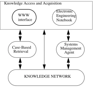
The architecture of the KAD system (Figure 1) centers on a knowledge network for storing design knowledge and providing services for the management of shared design,
and a WWW user interface for knowledge access and acquisition.
The KAD architecture also consists of an Electronic Engineering Notebook (EEN) as a knowledge acquisition tool, a case-based retrieval module for engineers to retrieve and re-use past design experience, and a systems management agent that monitors the systems engineering process for increasing productivity and quality. Case-based retrieval, systems management agent and electronic engineering notebook are reported elsewhere. In this paper we concentrate on the Knowledge Network serving as an information repository for the KAD system.
Figure 1 KAD Architecture
2
Knowledge Network Layers
WWW interface of the KAD system eases the barriers between engineers and the information technologies. It is found that engineers are quite comfortable with the browse and click techniques embedded in the web inter-face. The interface utilizes a Netscape client connected to a KAD server running on a Sun workstation. The client side can run in any platform of computing systems as long as it is supported by Netscape technology. All of the infor-mation appeared in the web interface is dynamically gen-erated from the knowledge network through the KAD server. Access to the knowledge network can be made by many clients simultaneously from across the enterprise through an enterprise-wide network or the Internet.
The knowledge network is an information system stor-ing engineerstor-ing design knowledge. In addition to tools for accessing and updating this knowledge, it provides ser-vices that support collaborative and concurrent design. The knowledge network includes six layers (Figure 2); from inner to outer layers, they are: Enterprise Object Model, Constraint Management, Version Management,
WWW interface
Electronic Engineering Notebook Knowledge Access and Acquisition
Case-Based Retrieval Systems Management Agent KNOWLEDGE NETWORK
Query Management, Design Management, and Access Management.
Figure 2 Knowledge Network Layers
The enterprise object model contains basic representa-tions (ontologies) of various knowledge in engineering design such as requirements, component structure, con-straints, parameters, versions etc. Constraint management handles propagation of engineering changes through a constraint network. Changes occur frequently in the design process. Constraint propagation plays an important role in understanding the impact of changes. Version man-agement controls the evolution of design and provides traceability of the transformation of objects being designed. Query management answers those common-sense and design relevant questions using information explicitly represented in the object model, and what can be deduced from it. Design management provides an environ-ment for engineers in which space of alternative designs and their impact can be explored. Access management defines who can access to the information in the shared design and what can be accessed. It controls the security checks of the WWW client connecting to the knowledge network. Each layer is implemented in ECLiPSe, a logic programming language obtained from ECRC. In the next few sections we will describe each layer of the knowledge network in detail.
3
Enterprise Object Model
The core of Knowledge Network is an enterprise object model developed within the context of TOVE (TOr-onto Virtual Enterprise) project [3], which aims at con-structing generic and re-usable ontologies for modeling the business operation of enterprises. An ontology is an object class library where objects, attributes and relations are precisely defined whenever possible using First-Order Logic. The object model provides a representation of data/
Enterprise Object Model Constraint Management
Version Management Design Management
Query Management Access Management
knowledge spanning product, process and organization. In addition, it includes rich representations of various enter-prise knowledge such as activity, time, causality, resources, cost, quality and more. Object class library for engineering design provided by the enterprise object model includes:
• Component structure, parts, features, parameters, • Requirements, constraints, dependency, source, • Versions,
• Decisions, rationale, alternatives.
Component structure is represented by parts connected with the relationship “has_component”, as illustrated in Figure 3.
Figure 3 Component Structure
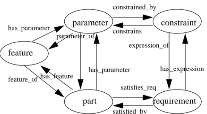
Features are used to describe geometrical and func-tional characteristics associated with a part. Both part and feature can have parameters that define their properties such as weight, color, diameter, material, surface finish, etc. Requirements specify the properties (functional, struc-tural, physical, etc.) of the artifact being designed. Con-straints form the leaves of the requirement decomposition tree, and embody physical laws, equations etc.
Parts, features, parameters, requirements and con-straints are related to each other with corresponding rela-tionships, as depicted in Figure 4.
Figure 4 Representing Design Knowledge
The knowledge stored in the object model is organized in an object-oriented fashion similar to ROCK knowledge base system from Carnegie Group. The basic units of rep-resentation are frame and slot. Frames are used for
repre-P1 P2 P3 P4 P5 ... ... has_component has_component parameter constraint requirement part feature expression_of has_expression constrained_by constrains satisfies_req satisfied_by has_parameter parameter_of has_parameter feature_of has_feature
senting objects, and slots representing the attribute, relationship, and procedural information of the objects. There are two types of frames: class and instance, where a class frame is used for representing a generalized type or category of object, and instance frame used for represent-ing a specific member of a class. Part, requirement, con-straint, parameter, etc. are all class frames organized as subclasses under a generic class called pro_object.
subclassOf (part, pro_object). subclassOf (requirement, pro_object). ....
A particular part (or requirement, constraint, ...) is an instance of part frame (or requirement frame, constraint frame, ..., respectively). For example,
instanceOf (PRT131, part).
There are three types of slots: attribute, relation, and
message. Attribute slots are used to store values. Relation
slots are used to store user-defined links between frames. Message slots are used to store methods which are exe-cuted in response to messages sent to the frame by some application program. For example,
attribute(PRT131, name, DeskSpotLamp). relation(PRT131, has_parameter, PAR23). message(PRT131, weight, getWeight).
Many predicates for accessing and updating the infor-mation stored in the frame and slot structure have been written. To get a flavor, we list some of them in the follow-ing:
kb_CreateClass(-Class): Create a class that is
indepen-dent of any other class.
kb_GetValues(+Frame,+Slot,-Value): Get the values
of the frame Frame of slot Slot through inheritance.
kb_GetRelatives(+Frame,+Path,-List): Get the list of
all frames that are linked (multi-level) to the frame Frame by relation Path.
The enterprise object model also includes the follow-ing representation (ontology) about project/organization: • Teams, resources,
• Responsibilities, authority, • Interactions, dependencies, • Activities, goals, milestones.
The activity ontology in the enterprise object model includes a state, which is a description of what is true and not true of the world at a particular time point or interval, and an activity, which is a transformational action primi-tive with which processes and operations can be repre-sented. Through reasoning about activity and states, the object model allows us to formalize the process of resource management, scheduling, product manufacturing and many other tasks within design and the operation of an enterprise. The activity and other ontologies have been reported elsewhere, e.g. [4].
4
Constraint Management
Constraints play an important role in design. It has been widely accepted that design is constraint oriented. To design means, to find a set of values for the attributes that do not violate any of the constraints. The design process involves the recognition, formulation, and satisfaction of constraints. Constraints are continuously being added, modified, and deleted throughout the development of a new product [6].
In case of a concurrent engineering environment the design is being simultaneously considered from various life-cycle aspects (or perspectives). Each one of these per-spectives puts forward some criteria (or constraints) that the design must satisfy. Not only these perspectives impose constraints on the design, they also try to push for-ward their concerns ahead of that of the others [1]. The constraints imposed by one perspective may interfere with that imposed by another perspective. When this happens, conflicts arise. Design can therefore, be looked as an active network of constraints and parameters.
Most of the previous work in the area of constraints has been in the area of design “solving”. It is only recently that researchers have started to look into the area of man-aging the design using constraints. The focus of the con-straint management layer is to support communication and coordination in concurrent engineering. This layer along with the systems engineering management agent (SMA)1 defines a tool which is used by the systems engineers to manage the design project.
4.1 Functions of constraint management layer Given a list of parameters that have been changed, the constraint management layer performs the following func-tions:
• Compilation of constraint network: Extract the net-work of all the parameters and constraints that could be affected by the change. We call this the “parameter span”, and “constraint span” of the change respec-tively.
• Impact analysis: Do constraint propagation on the above constraint network to find out the impact of the change on these affected parameters and constraints. • Based on the impact of the change look for
“symp-toms” that may have occurred and which need the attention of SMA.
1. As a part of this paper we have not described the SMA in detail. SMA can be considered as an indepen-dent, rule-based process which manages the systems engineering process.
• Inform SMA of the symptoms. The SMA in turn, takes necessary steps to “take care” of those symptoms. 4.2 Modes of operation
The constraint manager is available to the user in vari-ous kinds of flavors. The user may just like to have the constraints as “consultants”, in which case the constraints do an impact analysis and produce a report for the user. Or, the user may like to use the constraint manager act as a decision maker, in which case it implements the effects of the change and reflects it in the new state of the design. In the current version, the user sets a global flag to “analysis” or “implement” to switch between these two phases.
In addition, the user can analyze one change at a time, or the user can build a stack of changes over a period of time and analyze them all together. We also store previous design states, i.e., the states of design before a change was actually made. The user is always allowed to return back to a previous state if he so desires.
The user can decide to study the effect of change start-ing at three levels:
• Parameter Level: Start from an actual parameter that has been changed and do constraint propagation. In this case, the constraint manager calculates the “parameter span” and “constraint span”, and then does the constraint propagation
• Design Set Level: Start from a design set. (A design set is a private working space for a designer; the concept of design set will be described in detail in a later sec-tion). In this case, the constraint manager considers all the parameters and constraints in that design set and does constraint propagation.
• Design Level: Take the whole design into consider-ation. In this case, the constraint manager studies the whole design to find out what constraints are being vio-lated and how will the simultaneous consideration of all the constraints affect the parameter values.
There are various advantages of providing the con-straint manager at three levels.
• The parameter level is provided because an engineer working on a piece of work, and thinking of making a change may like to study the effect of that specific change which he/she will make to the parameter. • The design set level is provided because an engineer
may like to study the consistency of his design within the design set, before submitting the design set and making it available to other designers.
• The design level is provided to make sure that all the designs within the KAD system coexist in harmony. It may happen that a mechanical design is consistent
within itself, but in conflict with the electrical design. These inconsistencies can be revealed by running the constraint manager at the design level.
5
Version Management
Because of the evolutionary nature of design, changes occur frequently during the design process. Each object (parts, features, parameters, requirements, or constraints) may be undergoing many transformations before reaching its maturity. As a result of changes, versions of objects are created and kept in the system. The goals of version man-agement are to:
• Control the evolution of design objects,
• Allow traceability of previous design and ability to reverse design from one state to another,
• Provide design history and rationale.
The representation we developed for version has the following characteristics:
• Duplicate is minimized in the system. When a new ver-sion of a composite object (an object consisting of sev-eral (sub-)objects) is created, the system does not make copies of all of the sub-objects. Instead, only those involved in the changes are copied.
• Links between versions are automatically maintained, and users are allowed to specify a particular version as the current working version.
• System management agent (SMA) is automatically informed when new versions of significant objects are created. As a result, a system management process may be initiated and certain actions taken such as noti-fying appropriate persons of the new versions.
Version management is invoked when a designer sub-mits a portion of design from his working space (design set) to the Knowledge Network as a formal design. There are two kinds of submissions:
• Submit an object as a new version of another object already in the knowledge base. The first object essen-tially replaces the second one (which becomes an old version).
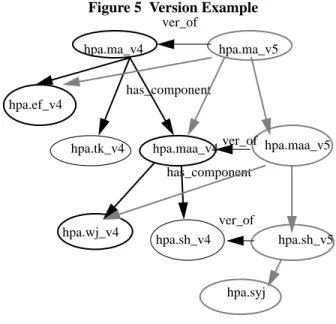
• Submit an object to the knowledge base that will then be linked to some other objects already in the Knowl-edge Network with some specified relations. For exam-ple, Figure 5 illustrates the submission of a new part hpa.syj (Handling and Positioning Aid shoulder yaw joint) as a component of hpa.sh (HPA shoulder). As a result of this submission, new versions of (the higher level components) hpa.sh, hpa.maa, hpa.ma are created (which is version 5). Note that only those that are involved in the changes are versioned.
Figure 5 Version Example
6
Query Management
Query management provides services for querying and updating the Knowledge Network.
For querying, we identify questions commonly asked by the designers. These are queries regarding product structure, versions, requirements, rationale, etc. Some que-ries are simple and typical in a day to day concern of an engineer or designer, e.g. “Who is the owner of part X?” or “What are the requirements on part X?”. These queries often require simple database look-ups and their process-ing is efficient. Definitions of objects, attributes and rela-tions (axiomatic semantics) is used to deduce answers to the queries. Other queries may be more complex and require powerful reasoning ability from the query proces-sor. For this purpose, the query management provides a first-order theorem prover which is used to deduce new knowledge (i.e. knowledge not explicitly represented in the knowledge base) from axioms and deductive rules in the knowledge network.
An example of a deductive rule is: “The engineer responsible for a part must approve all changes”. Then for the common sense questions such as “Who do I have to contact to make a change to the part?”, the answers are generated from the theorem prover by deduction from the rule.
An example of an axiom is “The weight of a part is equal to the sum of weight of its sub-components.” In our system, this is formalized as an axiom embedded in the Enterprise Object Model and is used in calculating weight of a component structure throughout.
How to present the answer to the users in a user-friendly way is an important issue in query management module. Because our query interface is part of the overall
hpa.ma_v4 has_component has_component hpa.ma_v5 ver_of hpa.ef_v4 hpa.sh_v4 hpa.tk_v4 hpa.maa_v4 hpa.wj_v4 hpa.maa_v5 hpa.sh_v5 ver_of ver_of hpa.syj
user interface in the project, which is based on a world wide web client-server architecture, it makes it quite easy for us to deploy the answer of queries back to the end user in a graphical format.
The query management module provides most update functionality of a conventional database, such as insert, delete and modify, where modify is viewed as a combina-tion of delete and insert. In either case, condicombina-tions can be imposed to locate proper information to update. In addi-tion, the service of updating a rule is provided. Updating rules is more complex and problematic than querying and updating facts in the knowledge base [5]. As an example, suppose we want to insert¬C into a knowledge base con-taining A, B and A ∧ B⊃ C, then it is not clear which piece of information (A, B or A ∧ B⊃ C) should be given up to keep the knowledge base consistent. When encoun-tering such a case, our system leaves the choice to the user. The user is free to choose which piece to revise if the knowledge base is inconsistent after an insertion/deletion.
7
Design Management
Design management provides an environment in which space of alternative designs and their impact can be explored. In preliminary design, objects are semi-struc-tured and relationships among the objects are unclear. Designers often re-use objects obtained from similar design cases, which can be results from a parametric search, a case-based retrieval, or a deductive query pro-cessing. Hence designers need a work space to store and manipulate the objects at their own will. That is, they need to work in an environment in which they can explore alter-native or partial designs without committing to them.
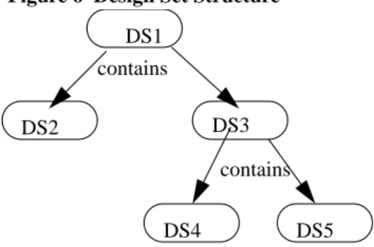
A design set is a work space for a designer to store and manipulate objects. The objects can be requirements, parts, parameters, features and constraints, or any others that are available to the designer. A designer can have one or more design sets where each design set may be struc-tured as design subsets (as shown in Figure 6).
Figure 6 Design Set Structure
Designer only accesses the design sets of their own or those that belongs to a group where the designer is a mem-ber. Design set operations include:
DS1 DS3 DS2 DS4 DS5 contains contains
• add, delete, modify, copy, etc.
• create design subsets, merge two design sets, move ele-ments from one design set to another, etc.
More importantly, designer may request the content of a design set be evaluated by the system’s constraint analy-sis functions. Designer can copy portion of current or pre-vious design into his design set where he can start the process of refinement and develop full relationship and structure of the objects. When he is satisfied with this por-tion of design, he can then submit the objects along with their relationships from the design set into the shared design.
8
Access Management
Access management is the outer layer of the Knowl-edge Network. It determines who (and where, when some-one) is allowed to access information stored in the database. Since Knowledge Network contains all the details of a product design, access control is very impor-tant; obviously a company must not allow competitors to intrude its database. Within an organization, some infor-mation can only be revealed to persons with certain roles, but not to the general employees. For example, the budget and current spending information of a project may only be known by, and under the control of, the project manager. Access management can extract, from the Enterprise Object Model, information about a person’s roles and responsibilities within the organization. Depending on this information, it then determines a particular user’s privi-leges of querying and updating the knowledge base.
9
References
[1] Bowen, J. and Bahler, D. “An Axiomatic Approach That Supports Negotiated Resolution of Design Conflicts in Concurrent Engineering”. Artificial Intelligence in Design’ 94, Edited By: J. S. Gero, and F. Sudweeks, Kluwer Aca-demic Publishers, Netherlands. 1994. pp. 363-379
[2] Crabtree, R., Baid, N., and Fox, M.S., (1993), “Design Engineering: Problems in Coordination”, in Proceedings of the JSME/ASME Design Theory Workshop, Tokyo Japan. [3] Fox, M., Chionglo, J.F., and Fadel, F.G., (1993), “A
Com-mon Sense Model of the Enterprise”, Proceedings of the 2nd Industrial Engineering Research Conference, pp. 425-429, Norcross GA: Institute for Industrial Engineers. [4] Fox, M.S., and Gruninger, M. (1994) “Ontologies for
Enter-prise Integration”, Proceedings of the 2nd Conference on Cooperative Information Systems, Toronto Ont, May 94. [5] H. Katsuno and A. O. Mendelzon. Propositional
knowl-edgebase revision and minimal change. Artificial Intelli-gence, 52:263-294, 1991.
[6] Serrano, D., and Gossard, D. Constraint Management in Conceptual Design. Knowledge Based Expert Systems in Engineering: Planning and Design, Editors: D. Sriram, and R. A. Adey, 1987, pp. 211-224