Southern Methodist University Southern Methodist University
SMU Scholar
SMU Scholar
Mechanical Engineering Research Theses and
Dissertations Mechanical Engineering
Spring 2020
Experimental Study and Numerical Simulation of Heat Transfer
Experimental Study and Numerical Simulation of Heat Transfer
and Fluid Flow in Laser Welded and Brazed Joints
and Fluid Flow in Laser Welded and Brazed Joints
Masoud Mohammadpour [email protected]
Follow this and additional works at: https://scholar.smu.edu/engineering_mechanical_etds
Recommended Citation Recommended Citation
Mohammadpour, Masoud, "Experimental Study and Numerical Simulation of Heat Transfer and Fluid Flow in Laser Welded and Brazed Joints" (2020). Mechanical Engineering Research Theses and Dissertations. 24.
https://scholar.smu.edu/engineering_mechanical_etds/24
This Dissertation is brought to you for free and open access by the Mechanical Engineering at SMU Scholar. It has been accepted for inclusion in Mechanical Engineering Research Theses and Dissertations by an authorized administrator of SMU Scholar. For more information, please visit http://digitalrepository.smu.edu.
EXPERIMENTAL STUDY AND NUMERICAL SIMULATION OF HEAT TRANSFER AND FLUID FLOW IN LASER WELDED AND BRAZED JOINTS
Approved by Dr. Radovan Kovacevic Dr. Blair Carlson Dr. Xin-Lin Gao Dr. Wei Tong Dr. Xu Nie
EXPERIMENTAL STUDY AND NUMERICAL SIMULATION OF HEAT TRANSFER AND FLUID FLOW IN LASER WELDED AND BRAZED JOINTS
A Dissertation Presented to the Graduate Faculty of the Bobby B. Lyle School of Engineering
Southern Methodist University in
Partial Fulfillment of the Requirements for the Degree of
Doctor of Philosophy With a
Major in Mechanical Engineering by
Masoud Mohammadpour
(B.S., Tabriz Azad University, Iran, 2010) (M.S., Urmia University, Iran, 2012)
Copyright (2020) Masoud Mohammadpour
iv
ACKNOWLEDGEMENTS
My sincere gratitude goes to Professor Radovan Kovacevic, my advisor, for his continuous support and guidance in my research and completing this dissertation. He has been my mentor any time I needed advice and I will never forget his sincerity and consistent encouragement. I would like also to appreciate my advisory committee members, Dr. Blair Carlson, Dr. Wei Tong, Dr. Xin-Lin Gao, and Dr. Xu Nie for their support and valuable suggestions.
My special thanks goes to Mr. Andrew Socha for his help in preparing experimental setups and providing technical assistance. I was fortune enough to have a number of wonderful colleagues in RCAM and very thankful for their invaluable help, friendship, and for all the good memories we have made in the last four years.
As always, I want to express my greatest appreciation for my parents, Alieh and Gholamreza, for their unconditional support and endless patience. I could never stand here without their unspeakable sacrifices. My sister and life mentor, Lida, has been so generous with her love and encouragement and I cannot thank her enough for that.
Last but not least, I am very grateful for my beloved wife, Saba, for her great companion, motivation, self-devotion, and patience during my graduate study.
v
vi
Masoud Mohammadpour B.S., Tabriz Azad University, Iran, 2010 M.S., Urmia University, Iran, 2012
Experimental Study and Numerical Simulation of Heat Transfer and Fluid Flow in Laser Welded and Brazed Joints
Advisor: Professor Radovan Kovacevic
Doctor of Philosophy degree conferred May 16, 2020 Dissertation completed May 5, 2020
Laser joining with advantages of high power density and high processing speed is becoming a dominant process for joining parts of the body in white (BIW) in automotive manufacturing. Aluminum alloys and new generations of advanced high strength steels (AHSS) are of great value for the automotive industry to build light weight, environmentally-friendly, high-quality, and durable vehicles. Their usage in body structure is increasing due to high strength-to-weight ratio and good formability. Lap and coach-peel joints are the most commonly used type of joints in assembly of the body components manufactured with each of these two alloys.
Laser brazing is a widely used process for joining closure panels in automotive manufacturing exemplified by joints such as the upper to lower panels of a liftgate or the roof to body side outer panels. Laser brazed seams are in visible areas and require a high quality surface and seam characteristics. Therefore, in this study novel techniques were studied to develop a robust welding and brazing processes of similar and dissimilar materials. Experimental studies as well as the numerical modeling and high-speed imaging approaches were used to gain a deeper understanding of the laser welding-brazing process, determine the effect of process parameters on weld dimensions, and analyze the dynamics of possible imperfections during the process.
vii
In dissimilar application, a feasibility study was conducted on laser joining of aluminum alloy to galvanized steel by means of twin-spot laser beams. Twin-spot mode was introduced to heat up a large surface area with less reduction in energy density for coach-peel joints with a wider geometry. The filler material was brazed on the steel side and partially fusion-welded on the aluminum side. The brazed results were investigated from the perspectives of microstructure evolution, tensile strength, surface roughness, edge straightness, and fracture mechanism. The generation of intermetallic compound (IMC) at the steel/seam interface was optimized by introducing a validated finite element thermal model to obtain the temperature history during the process and predict the thickness of a possible IMC layer. A multi-response optimization approach based on response surface methodology (RSM) was developed to find the fit model that correlated the main process parameters (laser power, wire feed speed, and scanning speed) and their interactions to surface roughness and mechanical strength. Under optimum processing condition the effects of alloying elements were also investigated on the performance of resultant joints. Different percentages of Si, Mn and Zn were introduced into the weld through three Al-based (AlSi12, AlSi5, and AlSi3Mn) and one Zn-based (ZnAl15) filler wires. Joint mechanical properties
were examined in terms of monotonic loading circumstance. Microstructural properties were evaluated in terms of the IMC layer thickness and composition.
In laser brazing of galvanized steels, the effect of laser beam inclination angle was investigated on process stability and spatter occurrence. Steel outer panels in automotive application are zinc coated for improved corrosion protection; however, the existence of low boiling element in coating has made the laser brazing process more challenging. Zinc has a boiling point of 907 °C which is lower than the melting range of copper-based filler wire, 965 – 1032 °C and as such is the predominant cause of laser brazing process instability and spattering for zinc
viii
coated steels. Therefore, experimental and numerical methods were applied to investigate the effect of laser beam inclination angle on laser braze quality of galvanized steels. High-speed videography revealed that spatter mostly occurred at the wetting line and melt pool front where the escaping zinc vapor came into interaction with the melt material. Application of a developed thermo-fluid simulation model considering laser-material interaction, wetting dynamics, material melting, and solidification, resulted in temperature profiles during the brazing processes for given beam angles as well as both the positions of the zinc evaporation front and wetting front. It was found that negative travel angles helped to move the zinc evaporation front ahead of the wetting front and reduce the interaction between the zinc vapor and melt pool. Experimental observations confirmed that partially removing and/or evaporating the zinc layer ahead of the wetting zone contributed to a stable process and good braze quality.
ix
TABLE OF CONTENTS
1.INTRODUCTION ... 1
1.1 Types of laser joining processes and applications ... 1
1.2 Application of galvanized steel and aluminum alloys in the automotive industry 3 1.3 Laser brazing ... 7
1.3.1 Effects of parameters in laser brazing ... 8
1.3.2 Dissimilar laser welding-brazing ... 11
1.3.3 Issues in the laser brazing process ... 13
1.4 Applications of numerical simulation in heat transfer, fluid flow, and structural analysis of laser welding-brazing process ... 15
1.5 Research objectives ... 18
References ... 20
2.EFFECT OF DUAL LASER BEAM ON DISSIMILAR WELDING-BRAZING OF ALUMINUM TO GALVANIZED STEEL ... 23
2.1 Introduction ... 23
2.2 Experimental procedure ... 26
2.3 Finite element modeling ... 30
2.3.1 Assumptions and Governing equations ... 30
2.3.2 Numerical procedure ... 32
2.4 Results and discussion ... 35
2.4.1 Microstructural characterization ... 35
2.4.2 Thermal field simulation and experimental validation ... 42
2.4.3 Surface roughness and Edge straightness ... 47
x
2.5 Conclusions ... 54
References ... 55
3.EFFECT OF FILLER WIRE COMPOSITION ON PERFORMANCE OF AL/GALVANIZED STEEL JOINTS BY TWIN SPOT LASER WELDING-BRAZING METHOD ... 58
3.1 Introduction ... 58
3.2 Experimental work ... 61
3.2.1 Material and methods ... 61
3.2.2 Measurements and characterization ... 64
3.2.3 Design of experiments ... 65
3.3 Parameters optimization ... 66
3.3.1 The effect of processing parameters on measured responses ... 66
3.3.2 Validation of the models... 71
3.3.3 Optimization ... 72
3.3.4 Zn-15%Al filler material processing parameters ... 74
3.4 Results and discussions ... 75
3.4.1 Microstructures and intermetallic layers ... 75
3.4.2 Tensile strength... 82
3.4.3 Surface roughness ... 85
3.5 Conclusions ... 86
References ... 87
4.INFLUENCE OF LASER BEAM INCLINATION ANGLE ON GALVANIZED STEEL LASER BRAZE QUALITY ... 90
xi
4.2 Experimental procedure ... 93
4.2.1 Materials ... 93
4.2.2 Experimental method ... 94
4.2.3 Characterization ... 97
4.3 Process simulation model ... 98
4.3.1 Computational domain ... 98
4.3.2 Mathematical Model ... 100
4.3.3 Numerical procedure ... 103
4.4 Results and discussion ... 104
4.4.1 Effect of different zinc coating ... 104
4.4.2 Visual analyses ... 107
4.4.3 High speed video observation – process monitoring ... 111
4.4.4 Simulation-based analysis ... 118
4.4.5 Macro-metallographic and SEM analysis... 121
4.4.6 Tensile test ... 124
4.5 Conclusions ... 126
References ... 128
5.SUMMARY AND FUTURE WORK ... 130
5.1 Effect of dual laser beam arrangement ... 130
5.2 Effect of filler wire composition ... 131
5.3 Effect of laser beam inclination angle ... 132
5.4 Future work ... 133
xii
LIST OF FIGURES
Figure Page
1.1 General classification of laser-based joining and manufacturing methods for engineering
applications [3]. ... 1
1.2 Effects of basic laser material interaction parameters in laser processes [4]. ... 2
1.3 Types of laser joining processes. ... 3
1.4 Application of laser welding in the automotive industry [6]. ... 3
1.5 Fuel economy standards by model year [9]. ... 4
1.6 The ductility - tensile strength of AHSS [15]. ... 6
1.7 General Motors’ first completed vehicle with a body made from mixed materials [16]. ... 7
1.8 (a-b) Typical configuration of laser brazing joints in BIW, (c) Development process in roof joining techniques [6]. ... 8
1.9 Influential parameters in laser brazing process. ... 9
1.10 (a) Developed multi- beam lasers for brazing process, (b) Comparison of energy distribution of YAG (left) and diode (right) laser beam [18]. ... 10
1.11 (a) The representation of dissimilar brazing, (b) Schematic cross-sectional view of aluminum to steel joint. ... 12
1.12 Fe-Al binary phase diagram [26]. ... 12
1.13 Different type of seam imperfections in the laser brazing process [30]. ... 14
1.14 Results of sessile drop tests with substrates at the room temperature (left) and preheated to 400℃ (right) [32]. ... 15
1.15 Schematic of physical phenomena in laser welding. ... 16
1.16 Different approaches in laser welding simulations. ... 17
1.17 Flowchart of thermo-mechanical and structural simulations procedure. ... 18
2.1 Laser welded-brazed coupon in coach peel configuration. ... 28
2.2 Schematic view of dual beams and their positions with respect to groove center. ... 28
2.3 The experimental setup and schematic view of arrangements. ... 28
2.4 The specimen prepared for tensile test (dimensions are in mm). ... 30
2.5 Laser power density distribution in dual-beam mode. ... 31
2.6 Dimensions of Finite element meshed model: (a) general view, (b) close-up of weld zone. . 33
2.7 Flowchart of extraction of meshed model from the cross section of an actual joint as well as the numerical simulation procedure. ... 34
xiii
2.8 Thermo-physical properties of galvanized steel, aluminum alloy and filler wire as a function
of temperature [15, 18]. ... 34
2.9 Microstructure of the LWB joint in cross-beam mode at different magnifications. ... 36
2.10 Microstructure of the LWB joint in in-line mode at different magnifications. ... 37
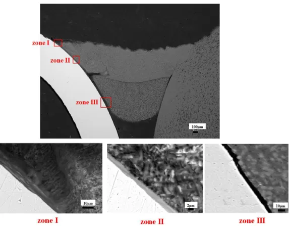
2.11 The measured thickness of IMC layer for cross-beam joint. ... 38
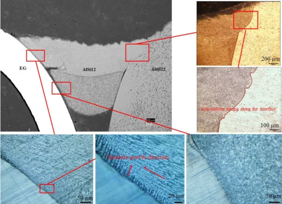
2.12 SEM image of brazed bead-steel interface and EDS line scan across the interface: (a) Al / EG - in-line, (b) Al / EG – cross. ... 38
2.13 Equilibrium AL-Fe-Si ternary phase diagram in the aluminum corner presenting distribution of IMC phase [21]. ... 40
2.14 EDS map scanning result of zinc distribution at substrate and brazed coat. ... 42
2.15 Temperature counter history in the joining process: (a) t=0.007 s, (b) t=0.1504 s, (c) t=0.451 s, and in cooling phase (d) t= 6.99 s. ... 43
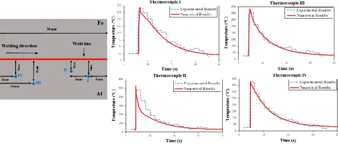
2.16 Schematic diagram of thermocouple positions and comparison between experimental and simulation results. ... 44
2.17 Comparison between (a) experimentally and (b) numerically obtained cross-sections by dual cross beam laser mode. ... 45
2.18 Comparison between (a) numerically simulated and (b) experimentally-obtained cross sections by dual in-line laser beam mode. ... 46
2.19 Simulated thermal histories at different locations along the brazing interface. ... 46
2.20 3-D view and cross section captured by optical profilometer for the joints: (a) Al / EG – in-line, (b) Al / EG – cross. ... 48
2.21 (a) Evenly spaced cross-sectional lines on the brazed seam to detect edge transition, (b) weld surface cross-sectional profile. ... 49
2.22 Schematic description of Rayleigh’s criteria. ... 50
2.23 The variation of edge straightness along the bead at the Al and steel sides: (a) Al-HDG, (b) Al-EG joints at a cross-beam configuration. ... 50
2.24 Tensile test curves for coach peel welded joints. ... 53
2.25 SEM fracture surface of the joint made Al / HDG – dual cross mode. ... 53
2.26 Fractured samples of tensile test: (a) dual cross beam, (b) dual in-line beam. ... 53
3.1 (a) Industrial application of aluminum roof-steel body side configuration, (b) dimensions of simplified coach peel configuration (mm). ... 62
3.2 Cross-sectional view of zinc coating. ... 63
3.3 (a) schematic view of experimental set-up, (b) close-up illustration. ... 63
3.4 (a) Perturbation plot showing the effect of all factors on the mechanical resistance, (b-c) Response surface and graphical counter of the effect of laser power and welding speed on mechanical resistance for AlSi3Mn1, Al4020 filler wire joints. ... 70
xiv
3.5 (a) Perturbation plot showing the effect of all factors on the surface roughness, (b-c) Response surface and graphical counter of the effect of wire feed rate and welding speed on surface roughness for AlSi3Mn1, Al4020 filler wire joints. ... 71 3.6 Predicted vs. Actual results and normal probability plots: (a) mechanical resistance, (b) surface
roughness for AlSi3Mn1, Al4020 filler wire joints. ... 72 3.7 Optimum condition and ramp reports of multi-response optimization for AlSi3Mn1, Al4020
filler wire joints. ... 73 3.8 SEM observation of cross section of the joint made by (a) AlSi12 and (b) ZnAl15. ... 75 3.9 SEM micrographs and distribution of alloying elements at the interface of steel substrate/braze
joint for different filler wire materials. ... 77 3.10 Formation process of the IMC layers during aluminum-steel LBW with Al-Si and Zn-Al
based wires. ... 79 3.11 Variation of IMC layer along the interface of brazed/steel for bead obtained by ZnAl15 filler
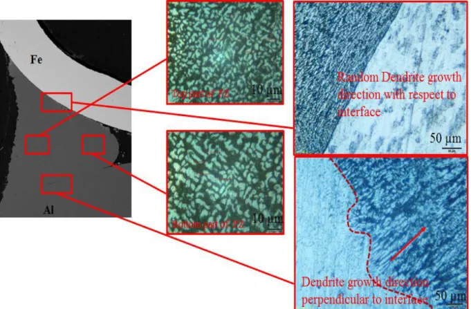
wire. ... 80 3.12 The morphology and orientation of solidified dendrites with respect to the steel/brazed bead
boundary for Al-based and Zn-based wire. ... 81 3.13 Hardness distribution of LWB joints. ... 81 3.14 (a) Resistance vs elongation, (b) Load/bonding area vs elongation, for the LWB joints with
AlSi3Mn1, AlSi5, AlSi12, and ZnAl15 filler materials. ... 83 3.15 Fractured surfaces of tensile coach peel coupons, note differing fracture modes associated
with the different filler wire material: (a) AlSi3Mn1, (b) ZnAl15. ... 84 3.16 (a) Experimental equipment for measuring surface roughness, bead surface and 3D
morphologies for (b) ZnAl15, (c) AlSi3Mn1. ... 85 4.1 Typical imperfections in laser brazing process: (a) surface pores; (b) spatter; (c) single-sided
wetting; (d) rises; (e) open-out blow holes; (f) skip; (g) saw tooth surface. [Note: experimental observations] ... 90 4.2 (a) Top and side view of fully clamped coupons in the welding fixture, (b) 3D laser beam and
filler wire relationship. ... 94 4.3 Schematic illustration: (a) work angle (WA); (b) travel angle (TA). ... 95 4.4 Schematic view of in-situ monitoring system. ... 96 4.5 Laser beam energy intensity distribution in focal plane: (a) 2D energy density contour, (b) 3D
energy density plot, (c) normalized energy distribution of a laser beam along the radial direction. ... 97 4.6 (a) Areas of interest for surface roughness measurement at the start, middle and end of the long
brazed coupon, (b) samples prepared for microscopic observation and mechanical tests, (c) geometrical features of a laser braze joint cross-section. ... 98 4.7 Schematic of computational domain with wire feeding. ... 99 4.8 Cross-sectional view of zinc coatings: (a) EG, (b) HDG. ... 105
xv
4.9 Successive images of bead-on-plate tests: (a) EG, (b) HDG. ... 105 4.10 SEM micrographs and EDX analysis of end craters of bead-on-plate tests: (a) EG, (b) HDG. ... 106 4.11 Intermittent breakage of zinc coating and wavy seam edge in laser brazing of HDG substrates. ... 107 4.12 Process map of the laser brazing window for HDG steel coupons. ... 108 4.13 Surface appearances and cross-sectional images of laser brazed joints with LP=3.8 kW: (a)
BS=65 mm/s, (b) WFS=60 mm/s. ... 109 4.14 Schematic representation of tool axis and wire feed forces. ... 110 4.15 (a) 3D morphology for TA=10, (b) measured surface roughness for travel angles, (c)
measured surface roughness for work angles. ... 111 4.16 (a-b) high-speed image sequences of molten pool under bubble formation, (c) illustration of
surface pore. ... 112 4.17 Successive images showing presence of micro-spatter in: (a) melt front, (b) degassing. .. 113 4.18 High-speed images of generated spatter in brazing process: (a) stuck, (b) re-entrant. ... 114 4.19 High-speed video images in brazing process with TA=-30: (a) covered hole, (b) existing hole,
(c) enlarged hole. ... 116 4.20 High-speed images of degas phenomena in laser brazing process with WA=5 ͦ. ... 118 4.21 (a) Comparison between numerically simulated and experimentally obtained cross-sections
(LP=3.8 kW, WFS=60 mm/s, BS=65 mm/s); (b) Temperature history at different steps of laser joining process. ... 119 4.22 Top view of simulated brazed seams under different TA angles. The isothermal line of the
zinc evaporation temperature (1180 K) is shown by a black line. ... 121 4.23 (a) Seam surface and micro section of brazed coupons at TA angles, (b) dimensional values
of brazing seam. ... 122 4.24 (a) Micro sections of brazed coupons at different WA angles, (b) dimensional values of
brazing seam. ... 123 4.25 SEM images and EDX scanning of the seam edges: (a) TA=20 ͦ , (b) TA=10 ͦ , (c) TA=-30 ͦ . ... 124 4.26 (a) Schematic view of prepared specimen for tensile test (dimensions are in mm), (b) base
metal fracture mode, (c) brazed bead fracture mode. ... 125 4.27 Predicted temperature history and seam cross sectional characteristics under TA=-30 ͦ and
xvi LIST OF TABLES
Table Page
1.1 Physical properties of shielding gases [23]. ... 11
2.1 Chemical composition of materials used. ... 27
2.2 Metallurgical features of possible IMC compound based on the EDS analysis of the interface of steel-Al for all LBW joints in atomic percent. ... 39
2.3 Thermodynamic data for a number of IMCs formed in Al-Fe and Al-Fe-Si system [21, 22] 40 2.4 The surface roughness values measured by an optical profilometer. ... 48
2.5 The edge straightness values measured by optical Keyence obtained for dissimilar joints. .. 51
3.1 Chemical composition of substrate materials. ... 62
3.2 Filler material alloy and melting range. ... 64
3.3 Process variables and experimental design levels for Al-based filler material (AlSi3Mn1, Al4020). ... 66
3.4 Design matrix and experimental measured responses. ... 67
3.5 ANOVA analysis for mechanical resistance of AlSi3Mn1, Al4020 filler wire joints. ... 68
3.6 ANOVA analysis for surface roughness of AlSi3Mn1, Al4020 filler wire joints. ... 69
3.7 Optimization criteria. ... 73
3.8 Confirmation experiments in the optimum processing condition for AlSi3Mn1, Al4020 filler wire joints... 74
3.9 Average thickness and EDS analysis of the dilution layer for different filler wires. ... 78
3.10 Measured surface roughness of four filler wire materials after welding/brazing using optimum processing parameters. ... 86
4.1 Chemical composition of CuSi3Mn1 wire. ... 94
4.2 Brazing conditions. ... 95
4.3 Thermo-physical properties of base and filler materials and related parameters used in the simulation [13]. ... 99
4.4 Type and number of captured defects in visual inspected samples. ... 110
4.5 Number of imperfections counted on recorded high-speed videos under different TA angles. ... 117
4.6 Number of imperfections counted on recorded high-speed videos under different WA angles. ... 118
1
Chapter 1
1. INTRODUCTION 1.1 Types of laser joining processes and applications
In last decade the utilization of laser-based material processing over traditional methods has increased tremendously. Contributing factors are the many advantages including the feasibility of complete automation, reaching a high processing speed, a higher quality product, cost reduction, and a smaller heat affected zone [1, 2]. Laser beam material processing is an umbrella term that refers to the four main groups of manufacturing process (1) forming, (2) joining, (3) machining, and (4) surface engineering [3]. A comprehensive classification of these laser-based fabrication techniques with a few representative examples from each category is provided in Figure 1.1. However, as the field matures, new developments and innovations continue to emerge in both the lasers themselves and their applications.
Figure 1.1 General classification of laser-based joining and manufacturing methods for engineering applications [3].
2
The common thread connecting these processes is their employment of lasers; however, each process utilizes distinct parameters. The most important parameters are the power density and interaction time that play a crucial role in changing the regimen of the process zone. As shown in Figure 1.2, the processing map can distinguish the different laser processes according to the laser power and interaction time. In this dissertation, two typical joining techniques, including laser brazing, and autogenous laser welding are considered.
Figure 1.2 Effects of basic laser material interaction parameters in laser processes [4]. Generally laser joining processes can be categorized into three main types (see Figure 1.3) laser brazing, autogenous laser welding (with conventional and remote scanner heads), and laser welding assisted with wire. These modern technologies are widely used in different industries to join various types of materials like carbon steel, high-strength steel, stainless steel, titanium alloys, nickel-based alloys, and reflective metals like aluminum and copper alloys in similar and dissimilar conditions. The main advantages over the other fusion welding processes can include the high processing speed, large depth/width ratio of the weld bead, and limited size of the heat-affected zone (HAZ)[1]. The automotive industry is the best example that has received great
3
benefits and has been completely revolutionized with the advent of laser joining processes. As shown in Figure 1.4 a large number of applications can be found in the powertrain, components, chassis, body in white (BIW), engine, interior, and exhaust systems [2, 5].
Figure 1.3 Types of laser joining processes.
Figure 1.4 Application of laser welding in the automotive industry [6].
1.2 Application of galvanized steel and aluminum alloys in the automotive industry
To identify the materials that have potential for use in car manufacturing several criteria like ease of manufacturing, environmental issues, low cost, design parameters, and manufacturing consistency should be considered in material selection [7]. In addition to these criteria, steel with
4
an effective combination of high strength, and low yield-to-tensile ratio is considered the predominant material in the automotive industry. Currently, most of the steel sheets in car-bodies are zinc-coated for the purpose of enhancing corrosion resistance as well as facilitating the stamping process and product durability. The zinc coating process can enhance the life time of manufactured parts with galvanized steel that has allowed automakers to provide voluntary warranties for corrosion protection lasting as long as 12 years [8].
To control global warming and reduce the emission of CO2, the U.S. Environmental
Protection Agency requires significant improvements in the fuel efficiency of vehicles. Fuel economy rules mandated that 2016 vehicle models were required to average 35.5 miles per gallon (mpg). This standard mandates an increase to 54.5 mpg by 2025 (see Figure 1.5) [9]. To achieve this goal, two main approaches have been proposed: development of new powertrain solutions and mass reduction in vehicle body weight. Reducing the overall weight of a vehicle was recognized as the most effective way to enhance the fuel efficiency. To tackle this approach, two main interests in alternative lightweight materials and development of advanced high-strength steel have been growing in the automotive industry.
5
The replacement of conventional steel by lightweight materials, such as aluminum (Al), magnesium (Mg), and titanium (Ti) for application in the skin panels and components has aroused the attention of researchers [10]. Aluminum is the most promising lightweight material due to its higher strength-to-weight ratio and lower cost over Mg and Ti. The application of aluminum alloys can reduce the weight of vehicles by up to 50% [11]. The utilization of aluminum has not been limited to casting components. Due to satisfactory performance, the application of aluminum has spread to the chassis construction frame and BIW assemblies [12]. In this regard Audi announced its intent to reduce the vehicle body weight by 40% in manufacturing the A8 model by using an aluminum-intensive space frame [13]. The construction of an automotive body structure typically consists of 6xxx series and 5xxx series aluminum alloys. Components such as latch and hinge reinforcements are made from 5xxx series non-heat treatable aluminum alloys while parts such as deck lids, roofs, and other outer panels are made of 6xxx alloys [13].
Joining aluminum alloys using either laser-based or resistance methods is more challenging than welding steel [14]. This can be attributed to the special features of aluminum alloys such as high reflectivity, high thermal expansion coefficient, high thermal conductivity, porosity generation during the welding process, and the oxide layer on the surface. Therefore, instead of finding better joining methods for alternative materials, some manufacturers have focused on development of new grades of advanced high strength steels (AHSS). The first generation (Gen. 1) of the AHSS family included dual phase (DP) steels, complex phase (CP) steels, transformation-induced plasticity (TRIP), and Ferritic-Bainitic (FB). The AHSS Gen. 1 was better positioned than conventional steels in terms of strength-elongation of the product. The AHSS second generation (Gen. 2) family achieved twining-induced plasticity (TWIP) and lighter weight with induced plasticity (L-IP). However, the higher cost of production was found to be prohibitive in finding
6
applications. Compared to Gen. 1 and Gen. 2 steels, the 3rd generation (Gen. 3) AHSS has a better combination of high strength and superior ductility. As a result, they have received an increasing interest from both the steel and automotive industries [15]. The well-known “banana plot” depicts tensile elongation of different AHSS generations as a function of strength (see Figure 1.6).
Figure 1.6 The ductility - tensile strength of AHSS [15].
A bypass and cost-effective method of producing a hybrid aluminum-steel structure is currently available in the BIW application [10]. This method achieves an even lighter vehicle with higher stiffness with respect to available materials. In this approach, the “mixed materials strategy” of using the right material in the right place in the right amount is applied. However, the entire vehicle is, in general, made from mixed materials, including the Al engine blocks and suspension parts, steel bodies, plastic trim, and Mg instrument panel support beams. Typically, such parts were attached to a predominantly steel body (i.e., a steel BIW) in final assembly. However, in this novel concept, the body structure is made from mixed materials incorporating several grades of steel and Al sheets. As shown in Figure 1.7 aluminum alloys can be used in nonstructural outer panels, such as roofs, hoods, fenders, and trunk lids. From both a mechanical point of view and an economical perspective, to maintain car crashworthiness, it is not possible to
7
replace steel as cheap as three times with aluminum. Thus, hybrid steel-aluminum structures have been introduced as a good replacement for many common all-steel body structures, making the joining of aluminum to steel inevitable [10]. This approach has opened up an attractive field of research for joining aluminum and steel alloys together.
Figure 1.7 General Motors’ first completed vehicle with a body made from mixed materials [16].
1.3 Laser brazing
Laser brazing is a metal joining process based on melting a cold/hot filler wire with a laser beam. The brazing wire is introduced into the braze seam via a wire feeder unit. The filler wire was heated above melting point allowing molten material to flow into the seam between two or more close-fitting parts by capillary action. In comparison to soldering, the temperature of brazing must be greater than 450 ℃ and lower than the melting temperature of the base metal. Laser brazing is a low-input process in which the defocused or magnified laser spot that is typically 1-2 times larger than the diameter of filler wire delivers a low energy level (105 W/cm2) during the
process [17]. At low levels of energy density, the laser beam only interacts with the surface of the weld bead, and then the heat is transferred to the interior by conduction in the so-called “laser conduction” mode. The high-speed processing condition up to several meters per minute at a very low-heat input is accompanied by a short heating time, small heating area, and low distortion. Laser brazing has been commonly used in the automotive industry for joining closure panels which
8
are in visible areas of the car body “class A joints”. Example applications are the joining of a roof panel to the outer body side, and the joining of an upper decklid panel to a lower decklid panel (see Figure 1.8 (a-b)). This process has dramatically revolutionized the BIW assembly not only in reduction of processing time but also the final joint quality. The resulting joints are aesthetically pleasing and require minimal secondary finishing [17]. As shown in Figure 1.8c the number of steps to complete the roof joint is decreased from 3 to 1.
Figure 1.8 (a-b) Typical configuration of laser brazing joints in BIW, (c) Development process in roof joining techniques [6].
1.3.1 Effects of parameters in laser brazing
The effecting parameters on the final quality of the joint during the process can be categorized into the three main sections of process parameters, heat source, and materials (see Figure 1.9).
9
Figure 1.9 Influential parameters in laser brazing process.
The heat source parameters consist of laser type, wavelength, beam diameter, continuous or pulse wavelength mode, energy distribution, and more importantly beam shape. The energy distribution plays a crucial role in this laser-based joining process, and it has significant effect on the final beads [18]. To enhance the quality and mechanical properties of laser brazed joints, along with the developments in single laser beam mode, several multi-beam laser modes were developed for this process [19, 20]. Figure 1.10 depicts different types of available multi-beam lasers for the application of the laser brazing process. The difference of energy distribution between Gaussian and Top-hat is also noticeable. The three main processing parameters (LP, BS, WFR) play a crucial role in the level of heat input and directly affect the stability of the process. Their individual changes can lead to process defects that are directly related to the level of applied energy level.
10
Figure 1.10 (a) Developed multi- beam lasers for brazing process, (b) Comparison of energy distribution of YAG (left) and diode (right) laser beam [18].
Laser brazing was developed to join steel and aluminum panels by means of Cu-based, Al-based, and Zn-based filler materials. Therefore, each set of material combinations with specific material properties are matter in final quality and process parameters. Laser efficiency, or laser energy transfer efficiency, describes the percentage of energy absorbed by the work-piece. This behavior directly relates to the material’s surface quality and reflectivity [21]. The combination of process parameters and efficiency determined by the processing parameter create a complicated physics behind the small size of the molten pool, including melting, fluid flow, mass and heat transfer, solidification, free-surface deformation, and interfacial reaction. Surface tension in the molten pool largely depends on its composition and temperature. Without considering the influence of heat input and chemical elements, the values of surface tension σsol−g, σsol−l,
and σl−g could be altered during the interaction of gas and the molten metal [22]. In addition, disturbances could be caused by the hydraulic pressure difference when the drop of filler wire falls into the molten pool. Pressure could build from the plasma plume and the shielding gas impinging
11
on the molten weld pool surface. Consequently, the idea to improve the weld surface quality by controlling the flow of filler wire into the molten pool and optimizing the shielding gas parameters comes naturally. Therefore, the type and flow rate of shielding gas is another influential parameter. Shielding gas not only protects the molten material from oxidation but also increases the laser absorption coefficient by blowing off the plasma and stabilizing the process. Zhang et al. [23] investigated the effect of gas composition on stability of laser processing. They found that different shielding gases have a tendency to form different plasma. The shielding gas with a lower molecular weight, higher thermal conductivity, and higher ionization energy will generate less plasma. As shown in Table 1.1, helium gas is the most effective to suppress the plasma and increase weld penetration. With respect to argon, helium as a low density gas requires a higher flow rate to provide better protection for the molten pool. Due to the economic consideration, argon or a mixture of argon and other shielding gases is normally chosen as the shielding gas.
Table 1.1 Physical properties of shielding gases [23].
Molecular weight (g/mol) Thermal conductivity (W/m.k) Ionization energy (ev) Helium 4 0.15363 24.6 Nitrogen 28 0.0255 15.6 Argon 40 0.01732 15.8
1.3.2 Dissimilar laser welding-brazing
Laser brazing process as a method for joining like materials was also implemented for dissimilar applications or so-called “laser welding-brazing” where aluminum panels are joined to dissimilar materials, such as steel [24]. Figure 1.11 shows a schematic view of a dissimilar concept in laser brazing. In the body structure of vehicles, aluminum alloys can be used in nonstructural outer panels, such as roof, doors, hood, front and rear fenders, and trunk lids. During the joining process, the aluminum substrate is melted, whereas the steel substrate is only wetted
12
by the Al-based filler material within a melting range of 570 ̊C-640 ̊C. When joining aluminum alloys to steels by laser, the large electrochemical difference, different thermal properties, dissimilar thermal expansion, heat capacity and thermal conductivity, different lattice transformation and melting points and nearly zero solid solubility are led to the generation of a brittle Al/Fe intermetallic compound layer at the interface [25]. Figure 1.12 represents the Fe-Al phase diagram and possible composition of intermetallic compounds at the dissimilar interface.
Figure 1.11 (a) The representation of dissimilar brazing, (b) Schematic cross-sectional view of aluminum to steel joint.
13
The formation of intermetallic is governed by a diffusion mechanism [27]. This mechanism is strongly related to the temperature reached at the Al/Fe interface and the time of interaction at high temperature related to the cooling speed. Therefore, the key point is finding a way to control the size and quantity of the Al/Fe intermetallic compound (IMC) layer. Schubert et al. [28] manipulated the diffusion process in laser welding of dissimilar materials by modifying the heat input. They could not only control but also restrict the formation of the IMC layer. The time and temperature dependent nature in growing the IMC layer can be resolved. Al5Fe2
is the first thermodynamically stable Fe-Al phase to nucleate, because Gibbs energy follows the sequence of ΔG0(Al5Fe2) < ΔG0(Al3Fe) < ΔG0(Al2Fe) < ΔG0(AlFe) < 0 < ΔG0(AlFe3)
[28].
1.3.3 Issues in the laser brazing process
In the automotive industry, laser brazing is expected to join the outer surface parts, because the heat input is easily controlled and the brazed bead appearance is very smooth and good [29]. A Cu-based filler wire is utilized for galvanized steel sheets, and Al-based filler wires are used for joining aluminum-to-aluminum and aluminum-to-steel sheets. As discussed previously several parameters are involved in this process. The correct tuning up of those parameters to an appropriate level of energy is a vital prerequisite to deliver high strength and smooth surface joints. In conditions with a higher energy level (high laser power, low brazing speed, low wire feed speed) defects like open-out holes, overheat, black soot, and more spatter may occur. In contrast, unmelted wire and rise are the typical defects that could be observed in lower energy levels. Figure 1.13 shows the typical brazed defects found in laser-brazed beads, resulting in degradation of the bead surface appearance and reduction in the joint strength.
14
Figure 1.13 Different type of seam imperfections in the laser brazing process [30].
The imperfections listed above can be classified as imperfections of the seam geometry. Some types of imperfection like unmelted wire (see 1st column of Figure 1.13) and one-sided wetting (see 2nd column of Figure 1.13) can be observed in both similar joints and aluminum-to-steel dissimilar joints. These defects can be attributed to the low energy level and misalignment of laser spot with the filler wire, respectively. The major cause for the formation of open-out holes can be attributed to (1) unsteady relation of wire feed and brazing speed; (2) low wire feed rates; (3) unsteady wire movement in the lateral and/or vertical direction (e.g., due to a large diameter wire nozzle). Porosity and spatter (see 3rd column in Figure 1.13) are merely the types of imperfection that are observed in laser brazing of galvanized steel sheets and dissimilar Al/Fe joints. These imperfections can be attributed to the existence of zinc coating on steel panels as the low boiling element. The zinc’s boiling point of 907 °C is lower than the melting range of copper-based filler wire 965-1032 °C. Kimura et al. [31] observed experimentally that high-pressurized zinc vapor expels from underneath the molten filler material. The vapor results in seam defects like open-out holes, porosities, and a large amount of it results as spatters. The highly-pressurized zinc vapor during the brazing process disrupts the melt pool stability. The vapor even can permeate the molten material and result in spatter defects. In a dissimilar joining process with the use of Al-based filler wires that have a lower melting range 570-640 °C than the boiling temperature of the zinc layer, there is a possibility of porosity generation inside of the brazed bead. During the
15
process at the interaction area, the zinc layer was liquefied instantaneously during wetting of the molten material on the coated substrate. The interaction between zinc and the filler material was also potentially governed by solubility effects. Zinc-related porosity might exist when the cooling time is too short to allow zinc to evaporate from the molten pool, as shown in Figure 1.14. Gatzen et al. [32] reported that preheating of the substrate can reduce zinc-related porosity and obtain small wetting angles. When the temperature of the substrate was elevated, the increased coating thickness (the local wt.% of zinc) was detrimental to the wetting and the width of the solidified droplets. Therefore, in the pre-heated condition, the zinc-coating should be as thin as possible to obtain increased wetting.
Figure 1.14 Results of sessile drop tests with substrates at the room temperature (left) and preheated to 400℃ (right) [32].
1.4 Applications of numerical simulation in heat transfer, fluid flow, and structural analysis of laser welding-brazing process
In recent years laser joining has become a more important technology that has found many industrial applications. Although, the physics behind this process has not yet been completely understood. The nature of laser beam welding and brazing processes are a combination and interaction of several physical effects such as laser and material interaction, phase change, fluid
16
flow, heat and mass transfer interaction of solid, liquid, and gas phases (Figure 1.15). The findings through experimental investigations provide valuable information in understanding the physics of process, dynamic correlations, and defects. Unfortunately, based just on experimental studies, some useful information is difficult to acquire, such as temperatures near or inside of the molten pool, pressure distribution in keyhole area, the fluid velocity field, solidification rate, flow direction, and so forth. Therefore, simulation can be a useful tool for a complete understanding of the process and formation mechanism of defects.
Figure 1.15 Schematic of physical phenomena in laser welding.
Another advantage of laser joining simulation is help for process optimization that could dramatically decrease the amount of costly and time consuming experiments. Numerical simulation can be utilized to predict the joint geometry, microstructure, temperature history, and other weld properties. These properties used to be obtained through trial-and-error experimental works [33]. As discussed earlier laser joining is a complex phenomenon that requires a “multi-physical” aspect for simulating the process. In spite of the rise in computer efficiency, a complete simulation, starting from light propagation until structural distortion, is currently not conceivable. For the moment, numerical codes are constrained to simulate the process scale by scale and to concatenate results. For example, the first step is laser and material interaction (multiple
17
reflection) that provides heat input to a heat transfer and fluid flow calculation. Then, heat transfer and fluid flow simulations, are coupled with a free surface tracking method and a multiple reflection consideration. The available heat distribution with the time, can be solved for a metallurgical problem to obtain material and phase properties and lead to a mechanical computation. However, there is no simulation model in literature that can encompass all of these physics in single model. As shown in Figure 1.16, the simulation of a laser joining process can be partitioned into two main groups of thermo-mechanical and multi-physical simulations [33].
Figure 1.16 Different approaches in laser welding simulations.
The first priority of industry is the design and optimization of manufacturing processes and components. The simulation can be a handy tool to improve the production sequences and to minimize production problems. For this reason a huge amount of models try to calculate the thermal history, mechanical effects of welding as residual strains and distortions, and mechanical performance of laser welded joints under monotonic and cyclic loading circumstances. The algorithm of thermo-mechanical simulation as the conductive heat transfer approach can be shown in Figure 1.17.
Thermo-mechanical simulation
• Heat transfer
• Mechanical stress and strain
• Metallurgical model for phase transformation
Multi-physical simulaiton
• Laser-material interactoin • Heat transfers and fluid flow • Moldelling of solid/liquid interface • Moldelling of liquid/gas interface
18
Figure 1.17 Flowchart of thermo-mechanical and structural simulations procedure. Numerical simulation based on multi-physic solutions provides a scientific and effective way to reveal the process mechanism of laser welding. Much research focuses on modeling of laser-material interaction, dynamic of keyhole, precisely capturing the free surfaces, and laser absorption mechanisms of material. The application of finite element analysis (FEA) and computational fluid dynamics (CFD) models in temperature field analysis of dissimilar laser brazing and autogenous laser welding processes was employed. The validated mechanical model was developed to study the effect of processing parameters on the mechanical performance of laser welded joints.
1.5 Research objectives
The single-beam and multi-beam laser welding-brazing techniques are investigated to join steel and aluminum panels in similar and dissimilar conditions. The effects of processing
19
parameters on the weld quality and robustness of process are investigated experimentally and numerically. An on-line vision system based on a high-speed video imaging accompanied with green laser illumination source are also used to gain a better understandings of the molten pool dynamic behavior and defect occurrence mechanisms. The main objectives can be listed as follow:
Implement a twin-spot laser joining procedure of dissimilar aluminum and steel in a coach peel configuration for the automotive industry. The main issues to address are the feasibility, quality of joint, process robustness, and formation of brittle intermetallic phases.
Develop a thermal simulation model to capture the effect of process parameters on the temperature fields with the purpose of optimization as well as to minimize the thickness of the intermetallic layer.
Conduct a comprehensive process parameters optimization to identify influential parameters, their interactions, and effect of the wire alloying elements on the mechanical strength and quality of dissimilar welded joints.
A novel method for measuring weld edge straightness is developed and an acceptable quality criteria based on human vision resolution is introduced.
Introduce a process window graph so-called “Brazibility graph” for the laser brazing of galvanized steels in roof joint of car-body.
Develop a thermo-fluid simulation model to study the formation of braze seam and calculate the temperature history and velocity fields in the melt area.
20 References
[1] K.J. Lee, S. Kumai, T. Arai, Interfacial Microstructure and Strength of Steel to Aluminum Alloy Lap Joints Welded by a Defocused Laser Beam, Materials Transactions, 46 (2005) 1847-56.
[2] W.M. Steen, J. Mazumder, Laser Welding. Laser Material Processing. London: Springer London; 2010. p. 199-249.
[3] J.D. Majumdar, I, Manna, Introduction to LaserAssisted Fabrication of Materials. In: Majumdar JD, Manna I, editors. Laser-Assisted Fabrication of Materials. Berlin, Heidelberg: Springer Berlin Heidelberg, (2013) 1-67.
[4] S. Williams, W, Suder, Use of fundamental laser material interaction parameters in laser welding. CLEO: 2011 - Laser Science to Photonic Applications, (2011) 1-2.
[5] J. Lu, V. Kujanpää, Review study on remote laser welding with fiber lasers, Journal of Laser Applications, 25 (2013) 052008.
[6] D. Havrilla, Laser Based Manufacturing in the Automotive Industry. 2010.
[7] G. Davies, Chapter 3 - Materials for consideration and use in automotive body structures. In: Davies G, editor. Materials for Automobile Bodies (Second Edition). Oxford: Butterworth-Heinemann, (2012) 93-143.
[8] S. Fujita, D. Mizuno, Corrosion and corrosion test methods of zinc coated steel sheets on automobiles, Corrosion Science, 49 (2007) 211-9.
[9] L. David, Greene, H. Howard, J.S.E.P. Baker, Reducing Greenhouse Gas Emissions From U.S. Transportation, (2011).
[10] K. Martinsen, S.J. Hu, B.E. Carlson, Joining of dissimilar materials, CIRP Annals, 64 (2015) 679-99.
[11] A.W. Alshaer, L. Li, A. Mistry, Understanding the effect of heat input and sheet gap on porosity formation in fillet edge and flange couch laser welding of AC-170PX aluminum alloy for automotive component manufacture, Journal of Manufacturing Science and Engineering, 137 (2015) 021011-13.
[12] R. Roth, J. Clark, A. Kelkar, Automobile bodies: Can aluminum be an economical alternative to steel? JOM, 53 (2001) 28-32.
21
[13] W.S. Miller, L. Zhuang, J. Bottema, A.J. Wittebrood, P. De Smet, A. Haszler, Recent development in aluminium alloys for the automotive industry. Materials Science and Engineering: A, 280 (200) 37-49.
[14] J. Matsumoto, H. Mochizuki, Spot welding of aluminium alloy ‐ electrode life for various electrodes, Welding International, 8 (1994) 438-44.
[15] H. Aydin, E. Essadiqi, I.H. Jung, S. Yue, Development of 3rd generation AHSS with medium Mn content alloying compositions, Materials Science and Engineering: A, 564 (2013) 501-8.
[16] M. Liu, Y. Guo, J. Wang, M. Yergin, Corrosion avoidance in lightweight materials for automotive applications, npj Materials Degradation, 2 (2018) 24.
[17] C.E. Mohammad Darvish, G. Evgeny, M. Holger, O. Andreas, Advantages of three-focal fiber technology in laser brazing of galvanized steel, Lasers in Manufacturing Conference (2017).
[18] G. Filliard, M.E. Mansori, M.D. Metz-Noblat, C. Bremont, A. Reullier, L. Tirado, Influence of process parameters on thermal cycle and intermetallic compounds formation in high speed laser weld-brazing of aluminium-steel angle joints, Procedia Manufacturing, 26 (2018) 690-9.
[19] S. Frank, Flux-free laser joining of aluminum and galvanized steel. Journal of Materials Processing Technology, 222 (2015) 365-72.
[20] G. Yang, J. Ma, B. Carlson, H.P. Wang, R. Kovacevic, Effect of laser beam configuration on microstructure evolution and joint performance in laser joining AA 6111 panels, Materials & Design, 123(2017) 197-210.
[21] M. Sokolov, A. Salminen, Methods for improving laser beam welding efficiency. Physics Procedia, 56 (2014) 450-7.
[22] G.M. Grigorenko, Y.M. Pomarin, V.Y. Orlovsky, Theoretical and experimental investigation of the thermodynamic and kinetic nitrogen absorption by liquid alloys, Materials Science Forum, 318-320 (1999) 25-30.
[23] M. Zhang, G. Chen, Y. Zhou, S. Liao, Optimization of deep penetration laser welding of thick stainless steel with a 10kW fiber laser, Materials & Design, 53 (2014) 568-76.
22
[24] P. Wang, X. Chen, Q. Pan, B. Madigan, J. Long, Laser welding dissimilar materials of aluminum to steel: an overview, International Journal of Advanced Manufacturing Technology, 87 (2016) 3081-90.
[25] S. Yan, Z. Hong, T. Watanabe, T. Jingguo, CW/PW dual-beam YAG laser welding of steel/aluminum alloy sheets, Optics and Lasers in Engineering, 48 (2010) 732-6.
[26] J.L. Murray, Fe–Al binary phase diagram, in: H. Baker (Ed.), Alloy Phase Diagrams, ASM International, Materials Park, OH, USA, 1992, p. 54.
[27] Y. Miyashita, Y. Mutoh, M. Akahori, Okumura, H.I. Nakagawa, Laser welding of dissimilar metals aided by unsteady thermal conduction boundary element method analysis, Welding international, 19 (2005) 687-696.
[28] H. Springer, A. Kostka, E. Payton, D. Raabe, A. Kaysser-Pyzalla, G. Eggeler, On the formation and growth of intermetallic phases during interdiffusion between low-carbon steel and aluminum alloys. Acta Mater. 59 (2011) 1586–1600.
[29] M. Heitmanek, M. Dobler, M. Graudenz, W. Perret, G. Göbel, M. Schmidt, Laser brazing with beam scanning: experimental and simulative analysis, Physics Procedia, 56 (2014) 689-98.
[30] D. Donst, P. Abels, M. Ungers, F. Klocke, S. Kaierle, On-line quality control system for laser brazing, International Congress on Applications of Lasers & Electro-Optics, (2009) 420-9.
[31] S. Kimura, S. Takemura, M. Mizutani, S. Katayama, Laser brazing phenomena of galvanized steel and pit formation mechanism, International Congress on Applications of Lasers & Electro-Optics, (2006) 528.
[32] M. Gatzen, T. Radel, C. Thomy, F. Vollertsen. Wetting behavior of eutectic Al–Si droplets on zinc coated steel substrates, Journal of Materials Processing Technology, 214 (2014) 123-31.
[33] M. Dal, R. Fabbro, An overview of the state of art in laser welding simulation, Optics & Laser Technology, 78 (2016) 2-14.
23
Chapter 2
2. EFFECT OF DUAL LASER BEAM ON DISSIMILAR WELDING-BRAZING OF ALUMINUM TO GALVANIZED STEEL
2.1 Introduction
To control global warming, the U.S. Environmental Protection Agency requires significant improvements in fuel efficiency. One of the best solutions to attain this requisite is to reduce the car’s weight by fabricating light weight alloys like Al materials. Nevertheless, to maintain car crashworthiness, aluminum alloys can substitute for steel structures to only some extent. Thus, hybrid steel-aluminum structures have been introduced as a good replacement for many common all-steel body structures, making the joining of aluminum to steel inevitable [1]. Regarding the joining of multi-component structures, the conventional joining processes have been studied and developed, including mechanical joining with rivets or screws, adhesive bonding, friction stir welding, explosive welding, and fusion welding [2]. Restrictions like slower assembly cycle and visibility of the rivets has made mechanical joining undesirable specifically in shell parts [3]. Solid state welding processes are extremely limited to the shape and size of joints so that only simple geometries such as butt and overlapping can be joined [4]. On the other hand, fusion welding of such dissimilar metals has posed many issues due to existence of significant differences between Fe and Al. The zero solid solubility of Fe and Al caused the development of undesirable brittle intermetallic compounds (IMCs) along the interface. It has been shown that an IMC layer with higher thickness reduces the strength of the joint significantly because of its low stress intensity factor as well as high crack propagation rate [5]. However, it was reported that the formation of IMC is useful to improve the wettability between Al and Fe, and good mechanical properties can
24
be achieved if the thickness of the IMC layer is less than 10 µm [6]. Thus, controlling the formation and growth of the Fe-Al IMCs is the current challenge of joining Al to steel.
In the subcategory of laser joining, a concept of laser brazing was developed for the joining the steel and aluminum panels. Recently the new concept of this process was proposed for the application of dissimilar metals. A liquid/solid state was utilized to join Al-steel where the diffusion of elements through the interface was limited and the reaction rate compared to the liquid/liquid state laser welding was minimized. Based on this concept, considerable attempts have been carried out for joining Al-steel structures by lasers. These studies involved a hybrid welding/brazing with a filler wire in which a fusion welding joint was formed at the aluminum side and a brazing joint was created at the steel side of the weld bead. In this type of joining technology, several solutions have been reported to restrict the growth of IMCs at the aluminum-steel side of the bead to sub-critical values [7]. The process temperature particularly at the interface of Al-steel is shown to have a huge effect on the growth of IMCs. Therefore, monitoring the thermal regime during the process as well as the resulting numerical prediction shouldbe of a great importance. Until now, only very limited literature in the field of numerical simulation models has been proposed to predict the temperature profile during Laser Welding-Brazing (LWB) [8-10]. Mathieu et al. [9] carried out an experimental and numerical approaches to measure temperature during the process. They showed that there was a specific temperate range in which the IMC layer had the greatest rate of growth. Applying the results obtained by numerical simulation, minimizing the process temperature, and process duration made it possible to keep the thickness of the IMC layer below a critical value.
Most studies of the laser joining process have been carried out by using a single laser beam. In some recent studies the advantages of using dual laser beams have reported in laser
welding-25
brazing processes. Yan et al. [13] observed that application of a dual beam Nd:YAG laser could generate an acceptable joint of steel/aluminum sheets and effectively reduce the presence of blowholes. As shown by Shen et al. [11] a tandem beam used for laser welding of dissimilar titanium alloys had higher strength and elongation than a single beam for laser welding. It was found that the dual-beam LWB compared to a single laser beam improved the process stability. LWB made a visually better-looking weld bead with a larger width. Furthermore, this weld bead increased the shear strength of the joint [12]. Li et al. [13] used cross-beam LWB to join the Zn-coated steel to a Mg alloy in a lap joint configuration. They revealed that the cross-beam mode was superior in reducing the wetting angle and promoting the spread of filler material with respect to the single beam mode.
The coach peel joint, due to the wider space between its panels in comparison to the other types of joints, needed to have a larger laser beam spot to cover the groove appropriately. As the laser spot size increased, the laser power should increase in order to have a high welding speed. To fulfill the requirement of larger beam size, some investigations were carried out recently. Frank S. [14] reported that a combination of continuous and pulsed laser beams in a circular-and-line-shaped mode perpendicular to the weld provided a good wetting at a welding speed of 3.6 m/min. Laserline Company announced a new laser head that generates a triple-spot laser for welding/brazing of similar and dissimilar materials. In this design two smaller laser spots are used to preheat the materials to be welded, and the laser spot in the middle is used to melt the filler material. Another beam arrangement that has good compatibility with the geometry of a coach peel joint is the dual laser beam that has been studied only on welding of similar aluminum [15]. This type of laser beam can deliver wider beams either across the weld groove or along it. To the
26
best of our knowledge, no research has been published on the dissimilar laser welding-brazing of coach-peel joints by implementing twin-spot laser beams.
However, there has been no comprehensive research done on understanding the correlation between either measured or predicted temperature profiles at the brazed joint interfaces and IMC thickness as well as joint mechanical properties at an elevated scanning speed. In this study, a high speed LWB process by means of two types of dual laser beam arrangement modes (cross and in-line) to join aluminum alloy to galvanized steel (hot-dip and electrogalvanized) in a coach-peel configuration was conducted. The surface quality of the obtained beads and the effect of IMC layer thickness on mechanical properties of the joint were also investigated. Furthermore, a method for measuring weld edge straightness was developed which is significant as straightness defines the quality of transition from the weld surface to the base metal. Finally, the numerical simulation using commercial software ANSYS was proposed to predict the temperature regime through either a weld or brazed interface.
2.2 Experimental procedure
The base metal used in this study was a 1.2 mm thick aluminum 6022 alloy coach peel panel and two types of galvanized low carbon steel coach peel panels with a thickness of 0.65mm (Hot-dip galvanized steel (HDG) and electro-galvanized steel (EG)). The filler wire used in this study was Al4047 with 1.6 mm in diameter. The chemical composition of materials are listed in Table 2.1.
27
Table 2.1 Chemical composition of materials used.
Substrates
and filler wire Alloying elements
Element Si Fe Mn Cu Mg Zn Ti Cr Al
Al 6022 0.8-1.5 0.05-0.2 0.02-0.1 0.01-0.11 0.45-0.7 0.25 0.15 0.1 Bal.
Al 4047 12.55 0.43 0.18 0.05 0.05 0.1 0.1 - Bal.
Element C Al Mn P Si S Fe Zinc layer THK (µm)
Low carbon
steel 0.003 0.034 0.11 0.01 0.005 0.05 Bal.
HDG 8-10 EG 12-16
An IPG fiber laser of 4 kW in power was used to carry out the welding of dissimilar materials (Al to steel). A brazed coupon is shown in Figure 2.1. The dual laser beam modes (cross-beam and in-line beam) were used with respect to the center of joint, and a schematic diagram of dual beams are shown in Figure 2.2. To obtain a dual laser beam shape, an optical beam splitter was mounted inside the laser head that split the laser beam in two beams with a power distribution of 50/50 on each side. The generated dual spots had the same diameter of 1.45 mm at the defocused plane and generated beams that had a 22.66% overlap of the spot. In an experimental setup, a laser head and Binzel wire feeding system were mounted on a 6-axis KUKA robot. The shielding gas used to protect the molten pool from an ambient atmosphere was pure argon with the flow rate of 25 SCFH. A schematic view of the experimental setup is illustrated in Figure 2.3 with the horizontal distance from the tip of shielding gas tube to the laser beam, the tilt angle of gas shielding tube, and the angle of filler wire. To protect the optics from direct reflections of laser beam, the laser head was also tilted at 5º. All experiments were carried out at a welding speed of 60 mm/s and wire feed rate of 70 mm/s. Because of the differences in beam mode and their energy distribution, the magnitude of optimum laser power for dual cross beam and dual in-line beam were selected as 3.2kW and 3.4 kW, respectively.
28
Figure 2.1Laser welded-brazed coupon in coach peel configuration.
Figure 2.2 Schematic view of dual beams and their positions with respect to groove center.
29
To obtain thermal cycles around the bead at both sides of Al and steel, the number of thermocouples were mounted close to the welded/brazed area. The temperature along the bead was measured by K-type thermocouple. The National Instruments data acquisition system was used to capture temperature at every 0.1 s. To quantify the surface roughness of the obtained beads, the surface profile of the bead was measured by the Micro Photonic Nanovea ST400/3D non-contact profiling device to ensure the surface roughness of the bead would be in an acceptable range. To obtain more reliable data, each measurement was reported three times for each laser welded/brazed joint, and the average was reported as the surface roughness. The edge straightness was another parameter that was measured by Keyence VR-3100 to get the edge waviness of the beads generated along the steel and aluminum panels. To acquire coupons for doing characterization and tensile tests, a water-jet cutting machine (integrated Flying Bridge Water-jet 4400, Flow International) was used. The typical sample prepared for tensile test is shown in Figure 2.4. Inspection of microstructure analysis of the joint cross sections was carried out by an optical microscopy and scanning electron microscopy (SEM) equipped by energy dispersive spectroscopy (EDS). The transverse cross section was mechanically polished using different grit sizes of sand paper (120 to 2000). Before the final polishing with 0.04 µm Al2O3 particle suspensions, the
samples were polished with a diamond paste of different particle sizes, 9, 6, and 1 µm. The polished cross sections were etched with a double etching process, first immersed in C2H5
OH-5%HNO3 solution for 5s and then a solution made of 1ml HF +1.5 ml HCl + 2.5 ml HNO3 +95 ml
30
Figure 2.4 The specimen prepared for tensile test (dimensions are in mm).
2.3 Finite element modeling
2.3.1 Assumptions and Governing equations
The goal of the finite element method was to obtain the temperature history during the LWB process. The actual process dealt with many parameters to simplify the FE model that didn’t affect the accuracy of simulation results. Therefore, the following assumptions were considered in the finite element thermal analysis of LWB of joining galvanized steel sheet panels to aluminum panels in a coach peel configuration:
1. The pre-constructed geometry of the joint was fixed before laser radiation.
2. The substrates and bead obtained by filler wire were taken into account as isotropic without considering the fluid flow of molten material and its spreading.
3. The applied heat from laser irradiation followed a double rotary Gaussian distribution.
4. The effect of shielding gas on heat input was neglected.
31
Due to the nonlinear transient nature of the LWB process and severe change of thermal as well as physical properties of the utilized materials, the differential equation of thermal conduction was applied: 𝜌𝜕(𝐶𝑝𝑇) 𝜕𝑡 = 𝑘 ( 𝜕2𝑇 𝜕2𝑥+ 𝜕2𝑇 𝜕2𝑦+ 𝜕2𝑇 𝜕2𝑧) + 𝑞̇𝑙𝑎𝑠𝑒𝑟(𝑥, 𝑦, 𝑧, 𝑡) (2-1)
where, 𝜌, 𝐶𝑝, T, t, 𝑘 and 𝑥, 𝑦, 𝑧 were the material density, specific heat, temperature, time, thermal conductivity, and Cartesian coordinates, respectively. For moving the heat source model, the laser induced volume heat source was described by the following equations for dual cross and in-line laser beams (see Figure 2.5) [16].
𝑞̇𝑙𝑎𝑠𝑒𝑟(𝑐𝑟𝑜𝑠𝑠 𝑏𝑒𝑎𝑚) = 9𝜂𝑄 𝜋𝐻𝑅02(1 − 𝑒−3)exp ( −9 𝑅02ln (−𝑦𝐻) ((𝑥 − 𝑥0± 𝑑)2+ (𝑧 − 𝑣𝑡)2)) (2-2) 𝑞̇𝑙𝑎𝑠𝑒𝑟(𝐼𝑛 𝑙𝑖𝑛𝑒 𝑏𝑒𝑎𝑚) = 9𝜂𝑄 𝜋𝐻𝑅02(1 − 𝑒−3)exp ( −9 𝑅02ln (−𝑦𝐻) ((𝑥 − 𝑥0)2+ (𝑧 − 𝑣𝑡 − 𝑑)2)) (2-3)
where 𝜂 was the absorption coefficient, 𝑄 was the nominal power of the laser beam, 𝑦 varied from 0 to H, H was the depth of the fusion zone, 𝑣 was the welding speed, 𝑅0 was the effective radius of the volumetric heat source on the material surface, and d was the center distance of dual beams.
![Figure 1.1 General classification of laser-based joining and manufacturing methods for engineering applications [3]](https://thumb-us.123doks.com/thumbv2/123dok_us/1389766.2686145/18.918.300.644.660.994/figure-general-classification-joining-manufacturing-methods-engineering-applications.webp)
![Figure 1.13 Different type of seam imperfections in the laser brazing process [30].](https://thumb-us.123doks.com/thumbv2/123dok_us/1389766.2686145/31.918.128.831.109.249/figure-different-type-seam-imperfections-laser-brazing-process.webp)
![Figure 1.14 Results of sessile drop tests with substrates at the room temperature (left) and preheated to 400℃ (right) [32]](https://thumb-us.123doks.com/thumbv2/123dok_us/1389766.2686145/32.918.234.709.483.699/figure-results-sessile-tests-substrates-temperature-preheated-right.webp)
![Figure 2.8 Thermo-physical properties of galvanized steel, aluminum alloy and filler wire as a function of temperature [15, 18]](https://thumb-us.123doks.com/thumbv2/123dok_us/1389766.2686145/51.918.171.774.548.991/figure-thermo-physical-properties-galvanized-aluminum-function-temperature.webp)
![Figure 2.13 Equilibrium AL-Fe-Si ternary phase diagram in the aluminum corner presenting distribution of IMC phase [21]](https://thumb-us.123doks.com/thumbv2/123dok_us/1389766.2686145/57.918.291.656.108.384/figure-equilibrium-ternary-diagram-aluminum-corner-presenting-distribution.webp)