Shterenlikht, A., Margetts, L., & Cebamanos, L. (2018). Modelling fracture
in heterogeneous materials on HPC systems using a hybrid MPI/Fortran
coarray multi-scale CAFE framework. Advances in Engineering Software,
125, 155-166. https://doi.org/10.1016/j.advengsoft.2018.05.008
Peer reviewed version
License (if available):
CC BY-NC-ND
Link to published version (if available):
10.1016/j.advengsoft.2018.05.008
Link to publication record in Explore Bristol Research
PDF-document
This is the author accepted manuscript (AAM). The final published version (version of record) is available online via Elsevier at https://doi.org/10.1016/j.advengsoft.2018.05.008 . Please refer to any applicable terms of use of the publisher.
University of Bristol - Explore Bristol Research
General rights
This document is made available in accordance with publisher policies. Please cite only the published
version using the reference above. Full terms of use are available:
Modelling fracture in heterogeneous materials on
HPC systems using a hybrid MPI/Fortran coarray
multi-scale CAFE framework
A. Shterenlikht1, L. Margetts2, L. Cebamanos3
1Mech Eng Dept, The University of Bristol, Bristol BS8 1TR, UK,
2School of Mechanical, Aero and Civil Engineering,
The University of Manchester, Manchester M13 9PL, UK, [email protected],
3Edinburgh Parallel Computing Centre (EPCC), The University of
Edinburgh, King’s Buildings, Edinburgh EH9 3FD, UK, [email protected]
April 16, 2018
Abstract
A 3D multi-scale cellular automata finite element (CAFE) frame-work for modelling fracture in heterogeneous materials is described. The framework is implemented in a hybrid MPI/Fortran coarray code for efficient parallel execution on HPC platforms. Two open source BSD licensed libraries developed by the authors in modern Fortran were used: CGPACK, implementing cellular automata (CA) using Fortran coarrays, and ParaFEM, implementing finite elements (FE) using MPI. The framework implements a two-way concurrent hierar-chical information exchange between the structural level (FE) and the microstructure (CA). MPI to coarrays interface and data structures are described. The CAFE framework is used to predict transgranular cleavage propagation in a polycrystalline iron round bar under tension. Novel results enabled by this CAFE framework include simulation of progressive cleavage propagation through individual grains and across grain boundaries, and emergence of a macro-crack from merging of cracks on preferentially oriented cleavage planes in individual crystals. Nearly ideal strong scaling up to at least tens of thousands of cores was demonstrated by CGPACK and by ParaFEM in isolation in prior work on Cray XE6. Cray XC30 and XC40 platforms and CrayPAT profiling were used in this work. Initially the strong scaling limit of
hybrid CGPACK/ParaFEM CAFE model was 2,000 cores. After re-placing all-to-all communication patterns with the nearest neighbour algorithms the strong scaling limit on Cray XC30 was increased to 7,000 cores. TAU profiling on non-Cray systems identified deficiencies in Intel Fortran 16 optimisation of remote coarray operations. Finally, coarray synchronisation challenges and opportunities for thread paral-lelisation in CA are discussed.
Keywords: fracture; heterogeneous materials; multi-scale; Fortran coar-rays; MPI; strong scaling; profiling; cellular automata; finite elements
1
Introduction
Deformation and fracture problems of solid mechanics often involve multiple competing physical processes occurring at different time and length scales. Examples of such processes are phase transformation (10ps, 10nm), disloca-tion nucleadisloca-tion and propagadisloca-tion (10ps, 50nm), twin formadisloca-tion (1ns, 1nm), interaction of dislocations (100ns, 100nm), secondary microcrack nucleation in the process zone (10ns, 100µm), adiabatic shear (10µs, 100µm). How-ever, engineering scale crack growth and component failure typically occur at much higher time and length scales (10−3 to 101s, 10−3 to 101m). A variety of multi-scale modelling approaches aimed to link different time and length scales together into a coherent model to deliver engineering scale pre-dictions have been proposed to treat such problems, e.g. combined atomistic and continuum mechanics [1], molecular dynamics and continuum mechanics [2], discrete dislocation and continuum plasticity [3], to name but a few.
The cellular automata (CA) method has been used together with finite elements (FE), in a multi-scale cellular automata finite element (CAFE) framework for problems involving material microstructure, such as solidifi-cation [4], recrystallisation [5] or fracture of polycrystals [6, 7, 8, 9, 10, 11]. FE is used to solve the continuum mechanics problem (coarse scale) to cal-culate the macroscopic quantities, such as the strain, stress or tempera-ture gradients, while the microstructempera-ture (fine scale) is updated with the CA method. At each iteration of the CAFE model continuum mechanics quan-tities are passed from the coarse FE scale to the fine CA scale (localisation) and damage variables are passed from the CA scale back to the FE scale (homogenisation) [12]. Thus CAFE is a two-way hierarchical concurrent multi-scale framework [13].
In the 3D CAFE method the Cartesian coordinate system is used and space is partitioned into identical cubic cells. Cells have physically mean-ingful states, e.g. liquid phase, intact crystal with a certain rotation tensor, crack front, crack flank, cleavage plane of a particular type, etc. [7]. The state of each cell at the next iteration is determined by the state of that cell, the states of its immediate neighbourhood cells, (e.g. the 26-cell Moore’s
neighbourhood) and some continuum FE field variables (e.g. stress, strain or temperature), all taken at the current iteration.
Most CAFE implementations to date use serial algorithms, partly be-cause of the lack of scalable FE solid mechanics solvers or due to restrictions of commercial FE packages [9, 10]. However, CA has an explicitly local do-main of influence, with no global equilibrium requirements, which opens opportunities for parallelisation. Each cell can be updated independently -in parallel. A much higher CA resolution can be achieved compared to the FE method, for the same computational cost. A recent study of CA per-formance on HPC has shown good strong and weak scaling up to 64 MPI processes on CPU [14].
This paper describes how a highly scalable CAFE framework for HPC was designed using a CA library implemented in Fortran 2008 coarrays and a FE library implemented in MPI. Examples of microstructures simulated using the CA approach are shown together with the description of the in-formation flow between CA (coarrays) and FE (MPI). Strong scaling results from multiple HPC systems are shown for multi-scale models of progressive brittle crack propagation in steel components. Finally a discussion of op-timisation possibilities of hybrid coarray/MPI codes, and challenges posed by choosing an optimal synchronisation strategy for a coarray library is presented.
This work is based upon [15], but the current paper includes the follow-ing additional research: CrayPAT and TAU profilfollow-ing and tracfollow-ing results, description of optimisation work, in particular replacement of all-to-all com-munication patterns with nearest neighbour algorithms, which led to over a three-fold increase in the scaling limit, and the latest strong scaling energy data from a Tier-0 Cray XC40 system.
2
Fortran coarrays
A brief introduction to Fortran coarrays is given in this section. For more details refer to [16, 17].
Fortran coarrays have been used as an extension to the standard for over 20 years, mostly on Cray systems. Their appeal to users increased substantially when they were standardised in 2010 [17]. Further coarray capabilities, such as collectives, teams, events and facilities for dealing with hardware or software failures, were published as a technical specification in 2015 [18]. These have been merged into a revised standard [19], which is expected to be published in 2018. All Fortran standardisation documents are available in open access from https://wg5-fortran.org, the home of Fortran standards.
Coarrays are a native Fortran means for single program multiple data (SPMD) type programming. A coarray is an extension of a Fortran array
data object in SPMD context. Square bracket syntax is used to define or refer to a coarray object, e.g. in the following code fragment
i n t e g e r :: i , ic [*] , k (10 ,10) , kc ( 1 0 , 1 0 ) [ * ] real , a l l o c a t a b l e :: r (: ,: ,:) , rc (: ,: ,:)[: ,: ,:]
all variables declared with [ ] are coarray variables, and : for allocatable variables means that dimensions and codimensions are chosen at runtime. At run time a certain number of identical copies of the executable (called images) are created by the operating system, which are executing asyn-chronously. Each image has read/write access to coarray variables on all other images: ic [5] = i ! the i n v o k i n g i m a g e c o p i e s its v a l u e of i ! to v a r i a b l e ic on i m a g e 5 ( r e m o t e w r i t e ) ! a l l o c a t e c o a r r a y v a r i a b l e rc on all i m a g e s a l l o c a t e ( rc (3 ,3 ,3)[5 ,5 ,*] ) ! the i n v o k i n g i m a g e c o p i e s the w h o l e of a r r a y rc f r o m ! i m a g e w i t h c o i n d e x set [1 ,2 ,3] to its own c o p y of ! a r r a y r ( r e m o t e r e a d )
r (: ,: ,:) = rc (: ,: ,:)[1 ,2 ,3]
The standard defines execution segments in a Fortran coarray program, which are separated by image control statements, such as SYNC ALL or SYNC IMAGES. SYNC ALL statement acts as a global barrier, similar to MPI barrier.
Coarrays can coexist with other parallel technologies, such as MPI or OpenMP, although to date there are only a few examples of such hybrid codes. The European Centre for Medium-range Weather Forecasts (ECMWF) has used coarrays in combination with MPI and OpenMP to achieve moder-ate scaling improvements [20]. Coarrays also have been used together with OpenMP in plasma codes [21].
3
Cellular automata modelling of microstructure
Dendritic grain growth with CA or with lattice Boltzmann methods have been studied extensively [22, 23, 4]. In this work a polycrystalline grain microstructure is created using a simplified solidification process, because the focus is on the fracture process of a final microstructure, and the exact solidification path is immaterial.
All cells are initially considered to be of liquid state, A certain number of randomly chosen cells represent grain nuclei. These are assigned states representing a randomly chosen orientation tensor. At each iteration of the solidification process a liquid cell can acquire the state of one of the 26
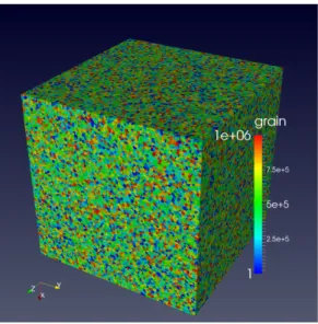
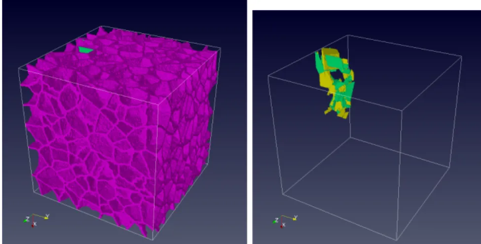
Figure 1: An example of the simulated equiaxed microstructure with 1M grains.
randomly chosen neighbours (Moore’s neighbourhood [24]). This process is continuing until there are no liquid cells left in the model. Both fixed and self-similar boundary conditions can be used [7, 25, 24].
A 3D CA space with cubic cells of discrete states maps perfectly onto a 3D integer array coarray, hence coarrays are a natural implementation choice for CA models. In contrast the FE part of the CAFE model, which implements the coarse scale continuum solid mechanics calculations, typi-cally has irregular boundaries. Most often MPI is used to implement parallel Lagrangian FE solvers.
The authors have developed a CA library for HPC systems, called CG-PACK, http://cgpack.sf.net. CGPACK is a free open source BSD-licensed library written in Fortran 2008 with extensive use of coarrays. All source code and full documentation are freely available from the above URL. Work on CGPACK started in 2013 on Cray XE6 [26]. CGPACK has since been ported to Intel and OpenCoarray/GCC platforms.
An example of an equiaxed microstructure simulated with CGPACK is shown in Fig. 1 where the colour denotes the orientation of each grain. This dataset has 106 grains simulated at a resolution of 105 cells per mean grain, i.e. 1011 cells in total. This model represents approximately a 18×18×18 mm3 volume of steel with the mean grain size of dof 0.2mm.
4
The coarray/MPI CAFE framework
This section describes how a highly scalable CAFE framework was designed via an interface between parallel FE and parallel CA libraries.
4.1 The FE part - ParaFEM
ParaFEM is written in Fortran 2003 with MPI [27]. It is a highly scalable and portable FE library,http://parafem.org.uk. It is a free open source software distributed under a BSD license fromhttps://sf.net/projects/ parafem. It is the latest extension of the sequential FE libraries originally written by Prof. Ian Smith and first published in the 1980s [28]. Inter-estingly, at that time, they were distributed as open source on tape by NAG Ltd. The software now comprises modules, subroutines, functions and around 70 example miniapps [29] (the miniapp (mini application) termi-nology is used after [30]). The miniapps are typically 2-4 pages long and are used to solve a variety of common engineering problems. The miniapp philosophy enables customisation by engineers, a feature that has enabled the work presented herein to be carried out with a reasonable amount of software development effort.
The parallelisation strategy adopted in ParaFEM involves working element-by-element at each stage of the finite element process, including building element stiffness matrices, solving the system of equations and recovering stress values (post-processing). No global matrix is ever assembled and so domain decomposition is avoided. Each MPI process is allocated an equal number of finite elements, balancing both computational load and memory usage. Parallel element-by-element versions of different iterative solvers are used for different problem types. These work in essentially the same way as their sequential counterparts [31], with the only difference being the need to pass messages between MPI processes when operating on distributed data structures.
The approach has been successful in solving a variety of problem types, from nonlinear material behaviour [32] to coupled systems involving multi-physics, such as Biot consolidation and magneto-hydrodynamics [33]. The software has led to scientific advances in a range of disciplines such as nuclear engineering [34, 35], biomechanics [36, 37], geomechanics [38] and palaeon-tology [39].
4.2 Size of the CA coarray
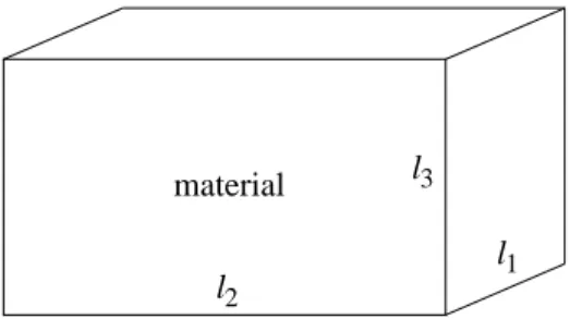
CGPACK modulecgca_m2phys deals with physical units and sizing of the main CA coarray. The 3D CA space is used to represent a rectilinear volume of material microstructure, of physical dimensions l1 ×l2×l3, see Fig. 2. The CA space is implemented as a 4D integer allocatable array coarray, with a 3D coindex set. The first 3 array dimensions identify a particular CA cell. The fourth array dimension is used to store multiple types of microstructural information, e.g. grains or damage [40]:
integer , a l l o c a t a b l e :: s p a c e (: ,: ,: ,:)[: ,: ,:]
material l 1 l 3 l 2
Figure 2: Schematic of the CA space.
at runtime, based on the available number of images, N. First the codi-mensions are chosen, c1, c2, c3, such that c1×c2 ×c3 = N. Arbitrarily we set c1 ≥c2 ≥c3. The codimensions are chosen to minimise c1−c3, i.e. to make the coarray grid as ‘cubic’ as possible. This is advantageous because it minimises the total number of halo cells, and thus the amount of remote data transfer. The quality of partitioning the microstructure into a 3D array of images is assessed by q = 1−(c1−c3)/(N −1), so that q = 1 means
c1=c3, i.e. the lowest possible number of halo cells whileq = 0 means that
c1=N, c2 =c3 = 1, indicating that the number of halo cells is maximised. Prior work showed that mesh independent CA results are achieved when each crystal (grain) is represented by at least 105cells on average [24]. Then, given the desired microstructure mean grain size, d, the first 3 dimensions of spaceare calculated.
As an example consider a simulation of a 12×12×20 mm volume of polycrystalline microstructure withd= 2mm on 192 images. Array space
with 2 types of microstructural information is then allocated as:
a l l o c a t e ( s p a c e (35 ,70 ,77 ,2) [8 ,4 ,*] )
wherec3 = 6. This allows for simulating 360 grains withq= 0.98, with the linear resolution of 23.2 cells per mm. The total size of the CA model is 280× 280×462≈36 million cells. In general it is not possible to represent physical space with the exact given dimensions, with the same linear resolution along each coordinate axis, as a discrete CA space. In this example, the volume of microstructure that is actually simulated is 12.06×12.06×19.91 mm.
4.3 Establishing the CA to FE mapping
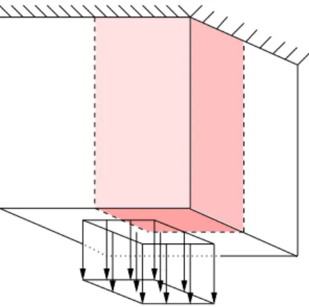
CGPACK module cgca_m3pfem contains data structures and subroutines which establish a mapping between the CA space and the FE mesh. A schematic example of an irregular FE domain is shown in Fig. 3. Some-times, the CA space will be fully inside the FE model, but in general, the CA space can be of arbitrary size and orientation with respect to the FE do-main, depending on what deformation and/or fracture phenomena are to be studied with it, as shown in Fig. 4. Some FEs will occupy the same physical
body (domain)
Figure 3: Schematic of the the FE domain.
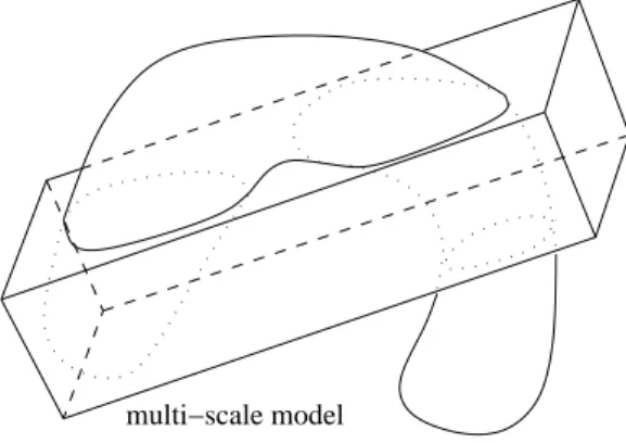
multi−scale model
Figure 4: Schematic of a multi-scale CAFE model composed of the FE domain superimposed with the CA material space.
space as some CA cells. These FEs and cells form a two-way macro/micro multi-scale CAFE model. However, as indicated in Fig. 4, in general, there will be cells occupying physical space outside of the body. Such cells do not participate in a multi-scale CAFE analysis. Likewise, FEs located outside of the CA space do not participate in the CAFE analysis.
The coarray/MPI CAFE framework is built with an assumption that at runtime there is always an identical number of MPI processes and coarray images, and that the first MPI process and the first image exist on the first processing element (PE), and so on, Fig. 5.
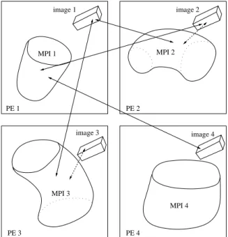
A schematic partition of the CAFE model on 4 PEs is shown in Fig. 6. The boxes show on which PE the corresponding parts of the model are stored. For example, ‘image 1’ and ‘MPI 1’ parts of the model are stored on PE 1. However, these FEs do not share physical space with these CA cells. Instead cells on image 1 share physical space with FEs on PE 3, labelled ‘MPI 3’. This is important because information transfer is required only between CA and FE which occupy the same physical space. In this example the MPI part of the model stored on PE 3 will have to communicate with the coarrays stored on PEs 1 and 3.
MPI 1 MPI 4 MPI 2 multi−scale model MPI 3 image 2 image 4 image 3 image 1
Figure 5: A possible partition of the multi-scale model on 4 PEs (right).
image 2 PE 2 PE 1 PE 3 PE 4 MPI 3 MPI 4 MPI 2 MPI 1 image 3 image 4 image 1
Figure 6: Schematic of communications between the MPI (FE) and the coarray (CA) parts of the coarray/MPI (CAFE) hybrid model on 4 PEs.
Communications between the MPI (FE) and the coarray (CA) parts of the coarray/MPI (CAFE) hybrid model are shown schematically with arrows in Fig. 6. Solid arrow lines represent comms between different PEs, while comms within a PE are shown with dashed lines. The imbalance in the comms pattern is clear. The FE part of the model stored on PE 4 will not communicate with CA at all. However, the FE part stored on PE 1 will need to communicate with CA coarrays stored on PEs 2 and 4.
The mapping of FE to CA is established via a private allocatable array of derived type:
t y p e m c e n i n t e g e r :: i m a g e i n t e g e r :: e l n u m r e a l :: c e n t r (3) end t y p e m c e n t y p e ( m c e n ) , a l l o c a t a b l e :: l c e n t r (:)
based on coordinates of FE centroids calculated by each MPI process (lcentr
stands for local, i.e. non-coarray array of centroids). These coordinates are stored in a coarray of derived type with a single allocatable array component:
t y p e rca real , a l l o c a t a b l e :: r (: ,:) end t y p e rca t y p e ( rca ) :: c e n t r o i d _ t m p [*] which is allocated as a l l o c a t e ( c e n t r o i d _ t m p % r (3 , n e l s _ p p ) )
where variable nels_pp, the number of FE stored on this PE, is calculated by ParaFEM and is made available to CGPACK.
There are two different routines which establish lcentr on each image from centroid_tmp. Subroutine cgca_pfem_cenc implements an all-to-all comms pattern, i.e. each image reads centroid_tmp from every image. Subroutinecgca_pfem_mapavoids an all-to-all comms pattern with the use of large temporary arrays and coarray collectivesCO_SUMandCO_MAX, which are defined by the coarray TS and the latest Fortran standard draft [18, 19]. The two routines differ in their use of remote comms. However, both routines implement the same algorithm for establishinglcentr: if the centroid of an FE on any image is within the CA coarray on this image, then this FE is added to lcentr on this image. Sec. 5.1 details profiling results and optimisation work done oncgca_pfem_cenc and cgca_pfem_map.
Fig. 7 schematically shows lcentrarrays established on two images P and Q. In this example, finite element n, stored on image Q, has centroid coordinates r, which identify a physical location within the CA coarray on image P. So this element is stored in the lcentr array on image P. Finite element m, also stored on image Q, has centroid coordinates u, which identify a physical location within the CA coarray also on image Q. So this element is stored in thelcentrarray on image Q. FEs with centroids outside of the CA space are not entered inlcentr. lcentrplays a key role in information transfer between the FE and the CA parts of the multi-scale CAFE model.
4.4 CAFE modelling of brittle fracture in polycrystals
Diverse CAFE fracture models can be constructed from the CGPACK and the ParaFEM libraries. The simplest case, presented here, uses a
combina-PE, image, MPI process P . . m . . . . n . . . elements image elnum centr . . . Q . . . P . . . CA lcentr . . . m . . . a . . . . . . u . . . t . . . u t PE, image, MPI process Q
. . b . . . . a . . . image elnum centr . . . Q . . . P . . . CA r s lcentr . . . n . . . b . . . . . . r . . . s . . . elements
Figure 7: lcentrarrays on two images P and Q.
tion of linear isotropic elastic FE with cleavage (fully brittle transgranular fracture mode) CA. Cleavage is the dominant low temperature fracture mode in body centre cubic (bcc) crystals, such as iron. At each time or strain in-crement of the FE solver, the stress tensor,t, is passed to the CA, where it is resolved into normal stresses on{100}and{110}crystal planes -t100, t110 [7, 12]. The localisation (or scatter) algorithm distributes the FE quanti-ties over CA cells based on existing damage in the microstructure, while preserving the FE energy [13].
The cleavage model includes 2 parameters - a fracture stress,σF, linked
to the free surface energy, γ, and a characteristic length, L. If t100 ≥ σF
ort110 ≥σF, then a CA cleavage crack is extended by L per unit of time.
Crack morphology is reduced to a single damage variable, D, by the ho-mogenisation (or gather) algorithm, and the Young’s modulus of each FE integration point is reduced according toD, whereD= 1 means no damage, and D = 0 means that the integration point has no load bearing capacity. To avoid numerical instability the FE stiffness is not reduced to below 10−3 of the original value (corresponding to D= 10−3).
4.4.1 The patch test
Schematics of a 3D static patch test and a quarter FE model are shown in Fig. 8. The deformed mesh is shown in Fig. 9.
Prediction of scatter is one of the strongest features of a probabilistic CAFE approach. In each run of the CAFE model a new random microstruc-ture is simulated which leads to the possibility of a stochastic structural integrity analysis. Figs. 10 and 11 shows two random realisations of a poly-crystalline microstructure leading to two unique crack propagation histories,
Figure 8: Schematic of the patch test with the quarter model highlighted.
Figure 9: The deformed FE mesh in the patch test, with the contours of vertical displacement. Colour version online.
and hence to unique macro-crack topologies and associated work of fracture.
4.4.2 A rod under tension
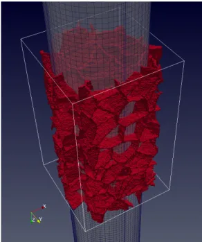
CAFE cleavage simulation in a rod under tension is shown in Figs. 12 to 15. The FE model is a 140mm long mild steel circular cylinder of 10mm diameter and 100mm gauge length. One end of the cylinder is constrained and an axial force is applied to the other end. The FE elastic properties are the Young’s modulus of 200GPa and the Poisson’s ratio of 0.3. Details of the CA material block were given at the end of Sec. 4.2. The CA block is positioned centrally on the cylinder, see Fig. 12.
Fig. 12 shows the polycrystalline microstructure layer of thespace coar-ray. The colour of each grain (single crystal) encodes its rotation tensor.
Fig. 13 shows the grain boundaries. Note that all inactive cells, i.e. CA cells which are outside of the FE domain and do not participate in the CAFE multi-scale analysis have been removed from this view.
Figure 10: Realisation 1 of CAFE showing grain boundaries (top image) and macro-crack (bottom image). Green cracks are on{110}planes. Yellow cracks are on{100}planes. Colour version online.
Figure 11: Realisation 2 of CAFE showing grain boundaries (top image) and macro-crack (bottom image). Green cracks are on{110}planes. Yellow cracks are on{100}planes. Colour version online.
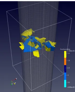
Fig. 14 shows the macro-crack emerging from linking cracks on preferen-tial cleavage planes in individual crystals. There are 4 cell fracture states in this model: -1, -2, -3 and -4. -1 (yellow) denotes crack flanks on{100}planes. -3 (light blue) denotes crack flanks on{110} planes. Both yellow and light blue regions are clearly visible in Fig. 14. -2 (dark blue) denotes crack fronts on{100} planes. -4 (cyan) denotes crack fronts on{110} planes. It is criti-cally important to appreciate the complexity of the macro-crack prediction. While it can be approximated as a plane normal to the axis of the bar, this approximation will ignore a wealth of information, such as grain boundary
Figure 12: CAFE modelling of a steel bar under tension showing the CA microstructure superimposed over the FE mesh of the bar. The mesh is semi-transparent for clarity. Colour version online.
Figure 13: The CA grain boundaries, with inactive cells removed. Colour version online.
Figure 14: Micro-cracks merging into a macro-crack in a steel bar under tension. Colour version online.
accommodation fractures and the orientations of preferential cleavage planes in individual crystals. These details allow for a more accurate prediction of the work of fracture, one of the key experimental validation parameters.
Cleavage fracture is inherently stochastic [41], meaning that it is in-correct to compare a single experiment against a single model prediction. Instead an experimentally measured distribution, e.g. of fracture energy, must be compared with a predicted distribution [9].
Also, as mentioned in Sec. 4.4.1 (The patch test) it is important to emphasise the stochastic nature of this model. By repeatedly running the model, a distribution of fracture parameters such as the work of fracture, can be predicted. Such distribution can be validated against a correspond-ing experiment, where such distribution is measured. The CAFE model is ideally suited for stochastic analysis and predicting distributions of the output parameters.
Fig. 15 shows the FE mesh at the end of the simulation, when the macroscopic cleavage crack has propagated across nearly the whole of the cross section. The contour plot of the axial displacement is superimposed over the mesh. Note a high displacement gradient across the crack.
It is important to highlight that a multi-scale CAFE model not only processes information at multiple scales, but also delivers useful predictions at each scale. In this particular case these are crack topology at the micro-scale (CA) and deformed mesh, continuum mechanics fields and energies at
Figure 15: The deformed FE mesh for a steel bar under tension with Z
displacement contours. Colour version online.
1 10 100 1000 10000 10 100 1000 10000 100000 T ime i n sec on d s
Number of MPI processes
Actual Ideal
Figure 16: Strong scaling of ParaFEM (MPI) for a 3D transient flow explicit analysis on Cray XE6. The problem has 1.25×10⁶ equations. The symbols show job times and the line denotes the ideal scaling. Reproduced from [29].
1 10 100 1000 10000 8 64 512 4096 32768 speed-up
Cray XE6 cores job time
ideal
Figure 17: Strong scaling of a CGPACK (coarrays) solidification model with 109 cells. 1 10 100 1000 10000 speed-up Cray XC30 cores original optimised ideal
Figure 18: Strong scaling of a ParaFEM/CGPACK (MPI/coarrays) CAFE fracture model.
5
Performance
Individually both ParaFEM and CGPACK libraries show nearly ideal scaling well into tens of thousands of cores, as seen in Figs. 16 and 17. Note that since both ParaFEM and CGPACK are libraries, scaling analysis makes sense only in context of specific programs built with these libraries.
A representative scaling of a CAFE multi-scale fracture simulation with 106FEs and 8×10⁸CA cells on Cray XC30 is shown in Fig. 18. The original scaling limit was only about 2,000 cores (80 Cray XC30 nodes), which was the starting point in the profiling and optimisation of the CAFE framework.
5.1 Cray XC30 profiling and optimisation
A Cray proprietary profiling and tracing tool CrayPat was used on a CAFE miniapp with 1M FE and 800M CA cells. This miniapp scaled well up to
Figure 19: CrayPAT profiling function distribution for a CAFE miniapp with all-to-all routinecgca gcupdaat 7200 cores.
Figure 20: CrayPAT raw profiling data for a CAFE miniapp with all-to-all routinecgca gcupda at 7200 cores.
2,000 cores from where the scalability dropped dramatically. The initial profiling study showed limited scalability mainly due to an all-to-all remote read routinecgca_gcupda, which accounted for over 38% of the total time, Figs. 19 and 20.
The key fragment from this all-to-all routine is shown below. In this rou-tine each image reads a coarray value from all other images. Even though the outer loop starting counter (remote image number) is chosen at ran-dom to even out communication load, this comms pattern leads to a poor performance at scale.
i n t e g e r :: g c u p d (100 ,3)[*] , rndint , j ,& img , g c u p d _ l o c a l (100 ,3) r e a l :: rnd : c a l l r a n d o m _ n u m b e r ( rnd ) r n d i n t = int ( rnd * n u m _ i m a g e s () )+1 do j = rndint , r n d i n t + n u m _ i m a g e s () -1 img = j if ( img . gt . n u m _ i m a g e s ()) & img = img - n u m _ i m a g e s () if ( img . eq . t h i s _ i m a g e ()) c y c l e : g c u p d _ l o c a l (: ,:) = g c u p d (: ,:)[ img ] : end do
An alternative to an all-to-all algorithm is the nearest neighbour algo-rithm. This has been implemented in subroutine cgca_gcupdn. The key fragment is shown below.
do i = -1 , 1 do j = -1 , 1 do k = -1 , 1
! Get the c o i n d e x set of the n e i g h b o u r
nc o d = m y c o d + (/ i , j , k /) : g c u p d _ l o c a l (: ,:) = & g c u p d (: ,:)[ n c o d (1) , n c o d (2) , n c o d ( 3 ) ] : end do end do end do
It must be emphasised that the nearest neighbour and all-to-all algo-rithms do not achieve identical results. In the nearest neighbour case the information is propagated only one image away from the current image. Mul-tiple invocations of the nearest neighbour algorithm are required for changes on any image to reach all images. However, because the nearest neighbour algorithm is known to scale well, it still outperforms all-to-all at scale, even if multiple invocations are used. Moreover, for some fracture propagation problems a single invocation of the nearest neighbour algorithm will suffice, if crack propagation rates are such that no crack is likely to cross the whole of CA array on an image in one CA iteration.
The execution of the mentioned miniapp exercising the nearest neighbour algorithm clearly demonstrates a considerable reduction in the number of remote reads. This can be seen on Figs. 21 and 22 where the user time is
Figure 21: CrayPAT profiling function distribution for a CAFE miniapp with the nearest neighbour routine cgca gcupdnat 7200 cores.
Figure 22: CrayPAT raw profiling data for a CAFE miniapp with the nearest neighbour routine cgca gcupdnat 7200 cores.
no longer dominated by remote reads between images with the exception of subroutinecgca_pfem_cenc.
Subroutine cgca_pfem_cenc also implements an all-to-all communica-tion pattern. It was possible to replace it with subroutine cgca_pfem_map, which uses temporary arrays and collectivesCO_SUMand CO_MAX.
tempo-rary array, of length in the order of the maximum number of FE on any image times the number of images, is required. This approach might prove problematic at very high core counts due to memory limitations.
i n t e g e r :: maxfe , p o s _ s t a r t , pos_end , & c t m p s i z e real , a l l o c a t a b l e :: tmp (: ,:) ! C a l c u l a t e the max n u m b e r of FE ! s t o r e d on t h i s i m a g e m a x f e = s i z e ( c e n t r o i d _ t m p % r , dim =2 ) c t m p s i z e = m a x f e ! The r e s u l t is a s s i g n e d to m a x f e ! on * all * i m a g e s c a l l c o _ m a x ( s o u r c e = m a x f e ) a l l o c a t e ( tmp ( m a x f e * n u m _ i m a g e s () , 5) , & s o u r c e = 0 . 0 ) ! E a c h i m a g e w r i t e s its d a t a in a u n i q u e ! p o r t i o n of tmp . p o s _ s t a r t = ( t h i s _ i m a g e () - 1)* m a x f e + 1 p o s _ e n d = p o s _ s t a r t + c t m p s i z e - 1 ! W r i t e i m a g e n u m b e r * as r e a l * tmp ( p o s _ s t a r t : pos_end , 1 ) = & re a l ( t h i s _ i m a g e () , k i n d =4 ) ! W r i t e e l e m e n t n u m b e r * as r e a l * ! T h i s w o r k s b e c a u s e FE n u m b e r s s t a r t ! at 1 on all MPI r a n k s . tmp ( p o s _ s t a r t : pos_end , 2 ) = & re a l ((/ ( j , j = 1 , c t m p s i z e ) /) , k i n d =4) ! W r i t e c e n t r o i d c o o r d tmp ( p o s _ s t a r t : pos_end , 3:5 ) = & t r a n s p o s e ( c e n t r o i d _ t m p % r (1:3 ,1: c t m p s i z e ) ) c a l l c o _ s u m ( s o u r c e = tmp )
All these optimisations led to over a 3 fold increase in the scaling limit, from 2,000 cores to about 7,000 cores, Fig. 18.
5.2 Profiling with TAU on Intel systems
In this section we describe the use of TAU to profile and trace CAFE miniapps using the Intel Fortran compiler and the Intel MPI library.
TAU [42], is a popular open source set of tools for performance analysis, particularly on HPC systems. Recently TAU (Tuning and Analysis Utilities) was shown to support coarray programs [43, 44]. In this work TAU 2.25.2 was used. The University of Bristol BlueCrystal phase 3 system was used for this work. Each node has a single 16-core 2.6 GHz SandyBridge CPU
Figure 23: TAU profile of a CAFE miniapp on 32 cores.
and 64GB RAM. Intel Cluster Studio XE, version 16.0.2, was used with the Intel MPI library 4.1.0. TAU was configured with
-mpi -c++=mpiicpc -cc=mpiicc -fortran=mpiifort
Intel implementation of coarrays uses remote memory access (RMA) one-sided communications of MPI-2, where a typical sequence of calls for a lock/unlock synchronisation is MPI Win create, MPI Win lock, MPI Put,
MPI Get,MPI Win unlock and MPI Win free [45].
Fig. 23 shows the profiling results for a CAFE fracture miniapp on 2 16-core nodes. The load is well balanced across all images. However,
MPI Win unlockdominates the run time andMPI Barrieris in second place. Only the miniapp program itself,xx14std, the halo exchange routine,cgca hxi,
the MPI FE routine,gather, and the fracture propagation routine,cgca clvgp nocosum, exceed the threshold of 1% of the total time.
Unfortunately, the conclusion from this profiling work is that coarray remote comms are not well optimised in Intel Fortran 16. Although Intel Fortran 17 has since been released, the authors have no access to this version to assess whether the performance of coarray implementation has improved.
5.3 Cray XC40 energy scaling
A Tier-0 EU level Cray XC40 system Hazel Hen, based at HLRS, Stuttgart, Germany was used for strong scaling energy studies, Figs. 24 and 25.
1 10 100 1000 1 10 100 1000 speed-up Cray XC40 nodes 10bn 80bn ideal
Figure 24: Strong scaling of 10bn and 80bn cell CAFE models.
0.1 1 10 1 10 100 Ener gy, MJ Cray XC40 nodes 10bn cells 80bn cells
Figure 25: Strong scaling of the total consumed energy for 10bn and 80bn cell CAFE jobs.
The CAFE miniapps revealed a bug in Cray Distributed Shared Memory Application (DMAPP) hardware dependent library [46], which manifested itself via coarray remote call errors at 300 nodes and beyond. Accordingly scaling was explored only up to 300 nodes on this system. The authors have been informed by Cray via HLRS that the fix is coming in Cray Linux Environment (CLE) version 6 (the current version is 5.2).
Figs. 24 and 25 show that the total energy of computation grows expo-nentially with increasing number of cores for these CAFE miniapps, even for a relatively good scaling, such as shown by a 10 billion cell CAFE model. Only for a truly linear scaling is is possible to keep the total energy of
com-putation constant, as seen in first 2 data points for a 80 billion cell CAFE model. The importance of reducing, or at least not increasing, HPC energy demands has been growing in recent years. Lately the aim of HPC has be-come not just to achieve the best scaling, but the best speed-up to energy ratio. With this in mind, data in Figs. 24 and 25 leads to the conclusion that the scaling limits are about 100 nodes for the 80 billion cell CAFE model, and about 10 nodes for the 10 billion model.
5.4 CAFE IO
A typical volume of microstructure in a CAFE approach might include 106 grains or 1011 cells. With 4-byte integers to store cell states, each layer of
space coarray will take ≈ 373GB, i.e. 745GB for both fracture and mi-crostructure datasets. Multi-step CAFE analyses, e.g. progressive fracture propagation through microstructure, demand thatspace coarray is written to disk at regular intervals. It is clear that efficient coarray IO is required for good scaling.
The Fortran standard does not include parallel IO. However, approaches to achieving high IO performance in MPI programs can be readily applied to coarrays [47].
A single writer/single file serial model is easiest to implement, but has the lowest performance, about 100MB/s on the Cray XE6. In contrast, a multiple writers/single file parallel model has the highest performance using MPI/IO. With some tuning of the Lustre file system, in particular lfs stripe size and stripe count settings, rates of 2.3 GB/s have been achieved on Cray XE6, raising up to 14 GB/s on Cray XC30 [47]. In all cases the CA space
coarray is written out as a binary dataset with no metadata. Knowledge of the array extents and of linear spatial resolution is required for post-processing.
NetCDF and HDF5 IO writers are beneficial to direct MPI/IO because the metadata is written either together with the data, as in the NetCDF case, or is encoded in a simple XDMF wrapper, as in the HDF5 case. Both NetCDF and HDF5 have been implemented in CGPACK. However, as Fig. 26 shows, at present maximum NetCDF IO rates are only about 1.2 GB/s [48], which is significantly lower than direct use of MPI/IO.
5.5 Synchronising a coarray library
The CGPACK library consists of a number of modules and submodules, with serial and parallel subroutines. A variety of programs can be built, using as many or as few CGPACK library routines as required. The design of the library makes only very basic assumptions on the order of calls to CGPACK routines in a program, e.g. fracture routines must be called after routines establishing microstructure. An error condition is flagged if the
0 0.2 0.4 0.6 0.8 1 1.2 1.4 1 2 4 8 16 32 64 IO rate, GB/s lfs stripe size, MB
Cray XC30, 20 nodes, lfs, NetCDF IO rates
count 1 count 4 count 8 count 16 count 20 count 32 count 40 count 56
Figure 26: CAFE IO rates showing the influence of the Lustre file system stripe size and stripe count settings.
order of these routines is reversed. In most other cases the logic of the order of the invocation of CGPACK routines is left to the user.
An immediate consequence of such design is that inter image synchroni-sation becomes a hard decision. The Fortran standard imposes very strict segment ordering rules to ensure data integrity and to prevent deadlocks [17].
Synchronisation requirements differ for each individual CGPACK rou-tine. For example, a halo exchange algorithm logically maps best ontoSYNC IMAGESimage control statement. Assuming a 3D grid of images, [:,:,:], see Sec. 4.2, each image has to synchronise only with its 26 neighbour-ing images, i.e. image with the coindex set [a,b,c] has to synchronise with images from [a-1,b-1,c-1]to[a+1,b+1,c+1]. However, the library writer has no way to predict what routines will precede or succeed the halo exchange routine. In practice this often means that the only safe image control statement is SYNC ALL, a global barrier. A fragment of a typical coarray CAFE program might look like this:
c a l l c g c a _ n r ( s p a c e ) ! s y n c all i n s i d e c a l l c g c a _ r t ( grt ) ! s y n c all i n s i d e c a l l c g c a _ s l d ( s p a c e ) ! s y n c all i n s i d e c a l l c g c a _ i g b ( s p a c e ) s y n c all c a l l c g c a _ h x i ( s p a c e ) s y n c all c a l l c g c a _ g b s ( s p a c e ) s y n c all c a l l c g c a _ h x i ( s p a c e )
s y n c all s y n c all
c a l l c g c a _ g c u ( s p a c e ) ! l o c a l r o u t i n e ! no s y n c n e e d e d
Note that some CGPACK routines include image control statements in the beginning and/or the end, e.g. cgca_sld, the solidification routine and
cgca_nr, the nucleation routine. It does not make sense to startcgca_sld
on any image until cgca_nr has finished on all images. In such cases the responsibility for arranging sufficient synchronisation has been taken away from the end user. However, in other cases, the user is likely to deploySYNC ALLto be safe, as shown above. The use of a more flexible synchronisation, e.g. SYNC IMAGES requires the user to have a very good understanding of the library routines used in their program. We are working on a dedicated synchronisation layer, which keeps track to updates of all coarray data ob-jects on all images and uses the minimum required synchronisation for data integrity. When implemented, this will move all or most of the responsibility for code synchronisation from end user to the CGPACK library itself.
While excessive use of SYNC ALLmight lead to over synchronisation, and hence to poor scaling, our prior profiling analysis on Cray XC30 concluded that the current ParaFEM/CGPACK (MPI/coarrays) scaling limit of 7,000 cores, see Fig. 18, is not related to this [40].
ParaFEM synchronisation properties are very different, because most of its routines use 2-way message passing MPI calls. In this regard it is very fortunate that in a ParaFEM/CGPACK CAFE program the calls to each library do not alternate often, - there is typically a large chunk of code made of ParaFEM calls, then SYNC ALL, then a large chunk of code made of CGPACK calls, etc. A fragment of a CAFE fracture program is shown below. c a l l c g c a _ p f e m _ s a l l o c ( nels_pp , nip , nst ) s y n c all ! end C G P A C K p a r t ! s t a r t P a r a F E M p a r t C A L L r e a r r a n g e ( r e s t ) e l e m e n t s _ 0 : DO iel =1 , n e l s _ p p CA L L f i n d _ g 3 ( g _ n u m _ p p (: , iel ) , & g _ g _ p p (: , iel ) , r e s t ) END DO e l e m e n t s _ 0
5.6 Opportunities for thread parallelisation
Many CA routines contain triple nested loops over all cells on an image. An example below is taken fromcgca_clvgp, the cleavage propagation routine. Each iteration of themainloop all cells in the CA on an image are processed.
m a i n : do i t e r = 1 , N do x3 = lbr (3) , ubr (3) do x2 = lbr (2) , ubr (2) do x1 = lbr (1) , ubr (1) l i v e : if ... ! s c a n o n l y t h r o u g h u n d a m a g e d c e l l s c a l l c g c a _ c l v g n ( c l v g f l a g ) if ( c l v g f l a g ) c a l l sub ( s p a c e ) end if l i v e end do end do end do ca l l c o _ s u m ( c l v g g l o b ) sy n c all ca l l c g c a _ h x i ( s p a c e ) sy n c all ca l l c g c a _ d a c f ( s p a c e ) end do m a i n
Such nested loops might present good opportunities for thread paral-lelisation with either OpenMP or OpenACC (e.g. on GPUs or Xeon Phi), although the use of underpopulated nodes might be required. Fortran 2008 new intrinsic DO CONCURRENT should also be explored, although at present its performance portability is inferior to OpenMP. Recently, ParaFEM has been ported to Xeon Phi [49]. In order to make best use of the Xeon Phi architecture, the code needed some rewriting to use a mixed OpenMP/MPI parallelisation strategy. On standard x86 multicore processors, the addition of OpenMP provides no benefit. However, on the Xeon Phi, OpenMP us-ing 4 threads per core provides an additional 4-fold speed-up in run times. Porting of CGPACK to Xeon Phi is planned for the future.
6
Conclusions
Coarrays are a new exciting feature of standard Fortran. It was shown in this work that coarrays are a natural data representation model for 3D cellular automata framework. The use of an integer allocatable array coarray with 4 dimensions and 3 codimensions in CGPACK for a 3D CA polycrystalline microstructure simulation was successful. It was shown that solidification and fracture of a polycrystalline microstructure can be modelled efficiently on HPC systems. Solidification models can scale at least up to 32k cores on Cray systems. A multi-scale continuum/microstructure model was con-structed by linking together cellular automata coarray library CGPACK with MPI finite element library ParaFEM. Considerable attention has been given to establishing a robust FE to CA mapping data structures and
pro-cedures, resulting in a concurrent hierarchical two-way multi-scale CAFE model. Coarrays of derived type with allocatable components were found to be very useful for maintaining dynamic data structures which link the MPI and the coarray parts of the framework. The multi-scale CAFE framework allows simulating the emergence of macro-cracks from merging cracks on preferentially oriented crystallographic planes in individual grains. A pro-gressive cleavage fracture propagation in a cylindrical ferritic steel specimen was shown as a simple CAFE application, which was scaled up to 7k cores on Cray XC30 after replacing all-to-all comms patters with nearest neigh-bour algorithms. A diverse range of other CAFE programs can be created by using ParaFEM with CGPACK. This work shows that interfacing MPI and coarrays is achievable in practice. This opens many possibilities for applications in other areas of science and engineering. In addition, because both ParaFEM and CGPACK are distributed under BSD license, the two libraries can be used by researchers from other fields, e.g. biomechanics for study of bone growth, fracture and regeneration.
Acknowledgements
The authors want to acknowledge generous funding for this work from the following organisations: (1) embedded CSE programme of the ARCHER UK National Supercomputing Service (http://www.archer.ac.uk); (2) the computational facilities of the Advanced Computing Research Centre, The University of Bristol, UK (http://www.bris.ac.uk/acrc); (3) PRACE for awarding us access to resource Hazel Hen based in Germany at HLRS, Stuttgart; (4) Software Sustainability Institute, UK (https://www.software. ac.uk).
References
[1] W. A. Curtin and R. E. Miller. Atomistic/continuum coupling in com-putational materials science. Model. Simul. Mater. Sci. Eng., 11:R33– R68, 2003.
[2] M. Xu and T. Belytschko. Conservation properties of the bridging domain method for coupled molecular/ continuum dynamics. Int. J. Numer. Meth. Eng., 76:278–294, 2008.
[3] M. Wallin, W. A. Curtin, M. Ristinmaa, and A. Needleman. Multi-scale plasticity modeling: Coupled discrete dislocation and continuum crystal plasticity. J. Mech. Phys. Solids, 56:3167–3180, 2008.
[4] G. Guillemot, Ch.-A. Gandin, and M. Bellet. Interaction between single grain solidification and macro segregation: Application of a cellular automaton - finite element model. J. Crystal Growth, 303:58–68, 2007. [5] C. Zheng and D. Raabe. Interaction between recrystallization and phase transformation during intercritical annealing in a cold-rolled dual-phase steel: A cellular automaton model. Acta Materialia, 61:5504–5517, 2013.
[6] L. Saucedo-Mora and T. J. Marrow. FEMME: A multi-scale Finite Element Microstructure MEshfree fracture model for quasi-brittle ma-terials with complex microstructures. Eng. Fract. Mech., 147:355–372, 2015.
[7] A. Shterenlikht and L. Margetts. Three-dimensional cellular automata modelling of cleavage propagation across crystal boundaries in poly-crystalline micro- structures. Proc. Roy. Soc. A, 471:20150039, 2015. [8] H. Talebi, M. Silani, S. P. A. Bordas, P. Kerfriden, and T. Rabczuk.
A computational library for multiscale modeling of material failure. Comput. Mech., 53:10471071, 2014.
[9] A. Shterenlikht and I. C. Howard. The CAFE model of fracture – appli-cation to a TMCR steel.Fatigue Fract. Eng. Mater. Struct., 29:770–787, 2006.
[10] S. Das, A. Shterenlikht, I. C. Howard, and E. J. Palmiere. A general method for coupling microstructural response with structural perfor-mance. Proc. Roy. Soc. A, 462:2085–2096, 2006.
[11] S. J. Wu, C. L. Davis, A. Shterenlikht, and I. C. Howard. Modeling the ductile-brittle transition behavior in thermomechanically contolled rolled steels. Met. Mater. Trans. A, 36:989–997, 2005.
[12] A. Shterenlikht, S. Margetts, L. McDonald, and N. K. Bourne. To-wards mechanism-based simulation of impact damage using exascale computing. AIP Conference Proceedings, 1793:080009, 2017.
[13] V. Kouznetsova, W. A. M. Brekelmans, and F. P. T. Baaijens. An approach to micro-macro modeling of heterogeneous materials. Comp. Mech., 27:37–48, 2001.
[14] E. N. Mill´an, C. S. Bederian, M. F. Piccoli, C. G. Garino, and E. M. Bringa. Performance analysis of cellular automata HPC implementa-tions. Computers and Electrical Engineering, 48:12–24, 2015.
[15] A. Shterenlikht, L. Margetts, and L. Cebamanos. Fortran coarray/MPI multi-scale CAFE for fracture in heterogeneous materials. In P. Iv´anyi,
B. H. V. Topping, and G. V´arady, editors,Proceedings of the Fifth In-ternational Conference on Parallel, Distributed, Grid and Cloud Com-puting for Engineering. Civil-Comp Press, Stirlingshire, UK, Paper 40, 2017. doi:10.4203/ccp.111.40.
[16] M. Metcalf, J. Reid, and M. Cohen.Modern Fortran Explained. Oxford, 2011.
[17] ISO/IEC 1539-1:2010. Fortran – Part 1: Base language, International Standard. 2010.
[18] ISO/IEC JTC1/SC22/WG5 N2074. TS 18508 Additional Parallel Fea-tures in Fortran. 2015.
[19] ISO/IEC JTC1/SC22/WG5 N2137. Fortran 2015 Committee Draft. 2017.
[20] G. Mozdzynski, M. Hamrud, and N. Wedi. A partitioned global address space implementation of the European centre for medium range weather forecasts integrated forecasting system. Int. J. High Perf. Comp. Appl., 29:261–273, 2015.
[21] R. Preissl, N. Wichmann, B. Long, J. Shalf, S. Ethier, and A. Koniges. Multithreaded address space communication techniques for gyrokinetic fusion applications on ultra-scale platforms. In Supercomputing 2011, USA, 2011.
[22] D. K. Sun, S. Y. Pan, Q. Y. Han, and B. D. Sun. Numerical simulation of dendritic growth in directional solidification of binary alloys using a lattice boltzmann scheme. INTERNATIONAL JOURNAL OF HEAT AND MASS TRANSFER, 103:821–831, 2016.
[23] M. Eshraghi, S. D. Felicelli, and B. Jelinek. Three dimensional simu-lation of solutal dendrite growth using lattice boltzmann and cellular automaton methods. JOURNAL OF CRYSTAL GROWTH, 354:129– 134, 2012.
[24] J. Phillips, A. Shterenlikht, and M. J. Pavier. Cellular automata mod-elling of nano-crystalline instability. In Proc. 20th UK ACME Conf., Manchester, UK, 2012.
[25] A. Shterenlikht, L. Margetts, L. Cebamanos, and D. Henty. Fortran 2008 coarrays. ACM Fortran Forum, 34:10–30, 2015.
[26] A. Shterenlikht. Fortran coarray library for 3D cellular automata mi-crostructure simulation. In Proc. 7th PGAS Conf., Edinburgh, UK, pages 16–24, 2014.
[27] L. Margetts. Parallel Finite Element Analysis. PhD thesis, University of Manchester, 2002.
[28] I. M. Smith. Programming the Finite Element Method. Wiley, 1982. [29] I. M. Smith, D. V. Griffiths, and L. Margetts. Programming the Finite
Element Method. Wiley, 5ed, 2014.
[30] M. A. Heroux, D. W. Doerfler, P. S. Crozier, J. M. Willenbring, H. C. Edwards, A. Williams, M. Rajan, E. R. Keiter, H. K. Thornquist, and R. W. Numrich. Improving performance via mini-applications. Technical Report SAND2009-5574, Sandia National Laboratories, Al-buquerque, New Mexico 87185 and Livermore, California 94550, 2009. [31] I. M. Smith and L. Margetts. The convergence variability of parallel
iterative solvers. Eng. Computations, 23:154–165, 2006.
[32] I. M. Smith and L. Margetts. Portable parallel processing for nonlinear problems. InProc. VII Int. Conf. Computational Plasticity, Barcelona, Spain, 2003.
[33] L. Margetts, I. M. Smith, and J. M. Leng. Parallel 3d finite element analysis of coupled problems. In Proc. III European Conf. Comp. Me-chanics in Solids, Structures and Coupled Problems in Engineering, Lisbon, Portugal, 2006.
[34] Ll. M. Evans, L. Margetts, V. Casalegno, L. M. Lever, J. Bushell, T. Lowe, A. Wallwork, P. Young, A. Lindemann, M. Schmidt, and P. M. Mummery. Transient thermal finite element analysis of CFC-Cu ITER monoblock using X-ray tomography data. Fusion Eng. Des., 100:100–111, 2015.
[35] J. D. Arregui-Mena, L. Margetts, D. V. Griffiths, L. Lever, G. Hall, and P. M. Mummery. Spatial variability in the coefficient of thermal expan-sion induces pre-service stresses in computer models of virgin gilsocar-bon bricks. J. Nuclear Mater., 465:793–804, 2015.
[36] F. Levrero-Florencio, L. Margetts, E. Sales, S. Xie, K. Manda, and P. Pankaj. Evaluating the macroscopic yield behaviour of trabecular bone using a nonlinear homogenisation approach. J. Mech. Behavior Biomed. Mater., 61:384–96, 2016.
[37] S. D. Rawson, L. Margetts, J. K. F. Wong, and S. H. Cartmell. Sutured tendon repair; a multi-scale finite element model. Biomech. Model. Mechanobiol., 14:123–133, 2015.
[38] L. Margetts, I. M. Smith, L. M. Lever, and D. V. Griffiths. Paral-lel processing of excavation in soils with randomly generated material
properties. In Proc. 8th European Conf. Numer. Methods in Geotech-nical Engineering, Delft, Netherlands, pages 265–270, 2014.
[39] L. Margetts, J. M. Leng, I. M. Smith, and P. L. Manning. Parallel three dimensional analysis of dinosaur trackway formation. InProc. 6th European Conf. Numer. Methods in Geotechnical Engineering, Graz, Austria, pages 743–749, 2006.
[40] L. Cebamanos, A. Shterenlikht, D. Arregui-Mena, and L. Margetts. Scaling hybid coarray/mpi miniapps on archer. In Cray User Group 2016 meeting (CUG2016), London, 8-12-MAY-2016, 2016.
[41] T. Lin, A. G. Evans, and R. O. Ritchie. Stochastic modeling of the in-dependent roles of particle size and grain size in transgranular cleavage fracture. METALLURGICAL TRANSACTIONS A, 18:641–51, 1987. [42] S. Shende and A. D. Malony. The TAU parallel performance system.
Int. J. High Perf. Comp. Appl., 20:287–331, 2006.
[43] H. Radhakrishnan, D. W. I. Rouson, K. Morris, S. Shende, and S. C. Kassinos. Using coarrays to parallelize legacy Fortran applications: Strategy and case study. Sci. Prog., 2015:904983, 2015.
[44] M. Haveraaen, K. Morris, D. Rouson, H. Radhakrishnan, and C. Car-son. High-performance design patterns for modern Fortran. Sci. Prog., 2015:942059, 2015.
[45] V. Tipparaju, W. Gropp, H. Ritzdorf, R. Thakur, and J. L. Tr¨aff. Investigating high performance RMA interfaces for the MPI-3 standard. In Proc. 2009 Int. Conf. Parallel Processing, 2009.
[46] Cray Inc. XC Series GNI and DMAPP API User Guide (CLE 6.0.UP01) S-2446, 2016.
[47] D. Henty, A. Jackson, C. Moulinec, and V. Szeremi. Performance of Parallel IO on ARCHER, version 1.1, 2015. http://archer.ac.uk. [48] A. Shterenlikht, L. Margetts, L. Cebamanos, and J. D. Arregui-Mena.
Multi-scale CAFE framework for simulating fracture in heterogeneous materials implemented in Fortran coarrays and MPI . InPGAS Appli-cation Workshop (PAW), Supercomputing 2016, USA , 2016.
[49] L. Margetts, J. D. Arregui Mena, T. Hewitt, and L. Mason. Parallel finite element analysis using the intel xeon phi. In Proc. Emerging Technology Conf. (EMiT 2016), ISBN 978-0-9933426-3-9, 2016.