Symbiotic Routing in Future Data Centers
Hussam Abu-Libdeh
∗ Microsoft Research Cambridge, UK.Paolo Costa
Microsoft Research Cambridge, UK.Antony Rowstron
Microsoft Research Cambridge, UK.Greg O’Shea
Microsoft Research Cambridge, UK.Austin Donnelly
Microsoft Research Cambridge, UK.ABSTRACT
Building distributed applications that run in data centers is hard. The CamCube project explores the design of a ship-ping container sized data center with the goal of building an easier platform on which to build these applications. Cam-Cube replaces the traditional switch-based network with a 3D torus topology, with each server directly connected to six other servers. As in other proposals, e.g. DCell and BCube, multi-hop routing in CamCube requires servers to participate in packet forwarding. To date, as in existing data centers, these approaches have all provided a single routing protocol for the applications.
In this paper we explore if allowing applications to im-plement their own routing services is advantageous, and if we can support it efficiently. This is based on the obser-vation that, due to the flexibility offered by the CamCube API, many applications implemented their own routing pro-tocol in order to achieve specific application-level charac-teristics, such as trading off higher-latency for better path convergence. Using large-scale simulations we demonstrate the benefits and network-level impact of running multiple routing protocols. We demonstrate that applications are more efficient and do not generate additional control traffic overhead. This motivates us to design an extended routing service allowing easy implementation of application-specific routing protocols on CamCube. Finally, we demonstrate that the additional performance overhead incurred when us-ing the extended routus-ing service on a prototype CamCube is very low.
∗Work done during internship at Microsoft Research,
Cam-bridge. Currently at Cornell University, Ithaca, NY, USA.
Permission to make digital or hard copies of all or part of this work for personal or classroom use is granted without fee provided that copies are not made or distributed for profit or commercial advantage and that copies bear this notice and the full citation on the first page. To copy otherwise, to republish, to post on servers or to redistribute to lists, requires prior specific permission and/or a fee.
SIGCOMM’10,August 30–September 3, 2010, New Delhi, India. Copyright 2010 ACM 978-1-4503-0201-2/10/08 ...$10.00.
Categories and Subject Descriptors
C.2 [Computer Systems Organization]: Computer com-munication networks; H.3.4 [Information systems]: Infor-mation storage and retrieval—Distributed Systems
General Terms
Algorithms, Design, Performance
Keywords
Data centers, key-value stores, routing protocols
1.
INTRODUCTION
The networks in large-scale data centers, such as those owned by Amazon, Google, Microsoft and Yahoo, adopt principles evolved from enterprise and Internet networking. Applications and services use UDP datagrams or TCP sock-ets as the primary interface to other services and applica-tions running inside the data center. This effectively iso-lates the network from the end-systems, which then have little control over how the network routes packets. The net-work operator controls the routing policies and configura-tions used in the data center.
This design impacts the services that run in the data cen-ter. External facing applications, like Search, Hotmail or Shopping Carts, rely on a set of internal distributed ser-vices. These services act as the building blocks for the ex-ternal facing applications, and examples of such services in-clude Google GFS [14], Google BigTable [6], Amazon Dy-namo [15], Yahoo Hadoop [4], and Microsoft Dryad [20]. Building services efficiently on current data centers is hard, in part because the network is a black box, and the services have to infer properties like end-system network proximity within the data center.
We have been exploring new data center architectures tar-geted at shipping container sized data centers, aimed at making it easier to build efficient services. We exploit the observation that many of the services running in data centers are key-based and have similarities with services that run on overlays. Conceptually, we want to take a topology used in a structured overlay and create a physical instantiation of that topology. Our prototype, called CamCube [7], uses a 3D torus (also known as a k-ary 3-cube) which is the topol-ogy used in the Content Addressable Network (CAN) [28] structured overlay. This creates a direct-connect topology,
where each server connects directly to a small set of other servers, without using any switches or routers. Using this topology means that the virtual and physical topologies are the same, and the key space is a 3D wrapped coordinate space, where each server is assigned an (x, y, z) coordinate that represents the server’s location within the 3D torus. The core CamCube API then exposes the coordinate space, and only provides functionality to send and receive packets to and from physical one-hop neighbors. This API with the coordinate space provides properties similar to those used in structured overlays. There have been other proposals for fu-ture data centers, including DCell [18] and BCube [17], that also explore incorporating hybrid direct-connect topologies in data centers.
Current data centers, as well as proposals for future ones, use a single routing protocol to route packets between ar-bitrary servers. They make explicit trade-offs, for example between exploiting multi-path and latency or server over-head. CamCube also has a base multi-hop routing service, using a link-state routing protocol that routes packets on shortest paths and exploits, where possible, the multipath characteristics of CamCube. As in existing data centers and proposals, we expected services running on CamCube to just use the base routing protocol. However, to provide simi-lar functionality to that of structured overlays, we allowed servers to intercept and modify packets as they routed them. We then observed that service designers exploited this flexi-bility to implement their own customized routing protocols, optimized for their particular performance requirements. In-tuitively, services implemented their own routing protocols because exposing the coordinate space and structure made implementing protocols that exploit the structure easy. Ser-vices often relied on the base routing protocol to handle cor-ner cases, such as coping with voids in the coordinate space. This leads to a commensal symbiotic relationship with multi-ple routing protocols running concurrently, all working with, and benefiting from, the base routing protocol.
In this paper, we examine four services developed for Cam-Cube that all implemented their own routing protocol. Each protocol is unique and makes different trade-offs, and we show that each service achieves better performance at the service-level by using its own routing protocol. We also ex-amine the network-level impact of having each service use its own routing protocol. Do the customized protocols increase network load? Do they induce higher control traffic? Are the traffic patterns skewed? Is there correlation between the sets of links used across protocol? We conclude that also at the network-level they achieve better performance while consuming less network resources. We also show, that across the set of services we have examined, that there is no correlated link usage, despite the fact that each service was designed independently. This leads us to conclude that enabling services to create their own routing protocols is advantageous.
Having determined that enabling services to use their own routing protocols is advantageous; we examine the core prop-erties of each protocol and extract a set of common func-tionality. We observe that in many cases the core properties required are conflicting. We then describe an extended rout-ing service that makes it easier for developers to simply and efficiently express their routing protocols. This ensures that wherever possible they can share state and resources, and hence decrease the likelihood that information is
indepen-dently maintained in multiple services, which would induce unnecessary overhead. It also makes it easier for service writers to write protocols and encourages reuse of already designed routing protocols.
The rest of the paper is organized as follows. Section 2 provides background on CamCube and direct-connect data centers. Section 3 outlines four services that use customized routing protocols. Section 4 examines the core properties of the routing protocols, and Section 5 describes the extended routing service to support them. Section 6 evaluates the overhead of using the extended routing service on CamCube. Section 7 shows an example service that uses the extended routing service. Finally, Section 8 describes related work and Section 9 concludes.
2.
BACKGROUND
Recently, there have been several proposals for data center architectures aimed at supporting shipping container-sized data centers. They currently have between 1,500 and 2,500 servers. Larger data centers are created by co-locating mul-tiple containers and, when delivered to site, the containers are provisioned with cooling, power and network links.
Many of the recent proposals have explored using non-traditional network topologies that are not simply based on switches and routers. Examples, include DCell, BCube and CamCube [18, 17, 7]. In these topologies, routing between two servers uses paths that traverse servers that are required to forward the packets. DCell [18] uses a hybrid topology, where conceptually servers (in the same rack) are connected to a local switch forming a DCell. Each server is then con-nected to another server in a different DCell. Hence, each DCell is connected to every other DCell via at least one server in the rack. To route packets between two servers in different DCells requires the packets to be sent via a server that is connected to a server in the other DCell. This server then routes the message to the other DCell server, which then locally delivers it within the DCell.
CamCube [7] uses a direct-connect 3D torus topology, formed by having each server directly connected to six other servers. All intra-CamCube traffic uses the direct-connect network, and hence no switches or routers are required. Un-like DCell and CamCube, in BCube [17] servers are only connected to switches, and a hierarchical structure is used. Conceptually, at the bottom of the hierarchy, servers in a rack are connected to a switch, that allows servers to com-municate within a rack. Each sever is also connected to one ofkother switches which are in the next level of the hierar-chy, such that each rack has one server connected to each of thekswitches. A packet can then be routed between racks by traversing multiple switches and multiple servers, using a source routing protocol.
Many of these topologies provide a significant number of independent paths between servers in the data center. In this paper we are exploring the viability and value of al-lowing services to explicitly exploit this multi-path. Before considering this further, we provide more details about Cam-Cube, the platform which we will use in this paper.
2.1
CamCube overview
CamCube is designed to make it easier to develop ser-vices in data centers. We provide a high-level overview of CamCube, for a complete description and design motivation see [7].
Communication between CamCube servers uses a direct-connect 3D torus topology. This is formed by having each server directly connected to six other servers and it does not use switches or routers. Each server is assigned an address, which takes the form of an (x, y, z) coordinate that repre-sents its relative offset from an arbitrary origin server in the 3D torus. We refer to the address of the server as theserver coordinateand, once assigned, it is fixed for the lifetime of the server. The CamCube API exposes the wrapped 3D co-ordinate space to services running on CamCube, and allows sending and receiving of raw (Ethernet) packets to one-hop physical neighbors. All higher-level functionality is built as services that run on top of this API, including multi-hop routing. The direct-connect topology is used for all intra-CamCube communication. Traffic from servers outside the CamCube is delivered over an IP-based switched network. We assume that any number from 1 to all servers can be con-nected to this network and, subsequently, CamCube servers do not assume that this network can be used to route packets to other CamCube servers. This allows the switched network to be provisioned just to support the expected ingress/egress bandwidth of CamCube.
The motivation for using the 3D torus topology, API and the use of the 3D coordinate space are structured overlays, specifically the CAN structured overlay [28]. The CamCube uses a physical wiring that is the same as the virtual topol-ogy used in CAN. The API is inspired by the Key-Based Routing (KBR) API [8] used in many structured overlays. Services written for CamCube can exploit the explicit struc-ture and are able to map keys into the coordinate space. This is motivated by the observation that many services built for data centers are very similar to applications built for structured overlays. However, CamCube applications benefit from the physical topology and virtual topology be-ing identical, meanbe-ing that the services do not need to try and infer properties, like end-system proximity, as it is more explicit.
We have written a number of network-level services that run over the direct-connect network, including a multi-hop routing service and a TCP/IP service that enables unmodi-fied TCP/IP applications to be run on CamCube. We also have a number of higher-level services, including a VM/file distribution service, an aggregation service that underpins a MapReduce-like service, and amemcached[13] inspired in-memory object cache. All services are implemented in user space, and the CamCube API communicates with a pair of drivers that run in the kernel.
2.1.1
CamCube API
Next, we provide more details about the CamCube API. We assume that each service running is assigned a unique
serviceId, and that an instance of each service runs on every server, which registers with the CamCube runtime. It is common to run services in data centers that are horizontally partitioned across all servers in the data center.
Packets have a simple two-byte header that contains the serviceId of the service that should handle the packet on each server. Each time a packet is received on a link, the kernel runtime delivers it and information about the source link to the service with the correspondingserviceId, which runs in user space, via a callback.
Originally, wanting to allow services to be able to manage queuing internally and exploiting the fact that all services
are cooperating, we used a multi-packet queue for each out-bound link. The CamCube API allowed a service to queue packets on the queue and query the queue length. How-ever, this simple approach made implementing fairness, even across multiplecooperatingservices, difficult. We therefore adopted a more complex hierarchical queuing mechanism, where conceptually there is asinglepacket queue per link. To send a packet a service can atomically check if the queue is empty and insert the packet if so. If not, the service is required to internally queue the packet. Whenever a packet is actually transmitted on a link, the services are polled in order until one has a packet to send. The packet is then queued, and the process repeats, ensuring fair queuing across services and allows the services to manage their own packet queues. In the runtime system we use an optimized im-plementation with low overhead. It is obviously trivial to extend this to incorporate weighted queuing across services, if required.
2.1.2
Core services
The CamCube API provides very limited functionality, and all other functionality is implemented as services that run on top of this API. We provide a number of core services that are assumed to be running on all servers in CamCube. These services provide the additional functionality required to write services that can perform higher-level operations on CamCube. The runtime allows services running on the same server to interact locally, so for example, the routing service can be accessed by all services running on the server.
The core services include a service that exposes the server coordinate, as well as the server coordinates of the one-hop neighbors, and also the size of the coordinate space. There is also a service to monitor liveness of one-hop neighbors, and if due to a server or link failure, other services are informed. Another core service is the multi-hop routing service that can be used to route a packet to a server. This uses a simple link state-based protocol, and maintains information about the reachability of all servers in CamCube. There is a high degree of path redundancy, meaning that there are multiple paths between servers. Routing uses shortest paths, but due to multi-path, it is often the case that multiple one-hop neighbors offer the same shortest path length to the destination. Therefore, this is exploited to allow packets to use the first free link that is on a shortest path. Any service that uses the routing service is able to intercept and modify, or even drop, a packet at each hop on the path. Packets routed to a failed or unreachable server will be dropped.
The routing service is able to perform key-based routing as well as server-based routing. In CamCube, as in CAN, keys are mapped into the coordinate space. In key-based routing the packet is delivered to the server responsible for the destination key (referred to as the key’s root server). Without failures, the mapping of keys to servers is trivial, and uses the servers 3D coordinate (as in CAN). In the pres-ence of failures, key-based routing will route the packet to another server which is numerically closest to the key. The service remaps the key consistently across all servers pro-viding a consistent key-space. In order to ensure good load distribution of keys to servers in the presence of failures, a deterministic tie-breaking mechanism is used. In the rest of the paper, we refer to a key coordinate when we are refer-ring to a coordinate independently of a server and a server coordinate when we are using the coordinate to refer to the
particular server with that address. The key-based routing, plus CamCube API, with the ability to perform per-hop inspection and modification of packets implements the full KBR API [9], widely used in structured overlays.
We did not use a greedy protocol in the routing service be-cause the server coordinates are static and, therefore, server failures create voids in the coordinate space. In 2D topolo-gies, techniques like perimeter routing [22] are able to route around the voids. However, in a 3D space these techniques are known not to work [12]. In overlays like CAN, the ad-dress of a server is a function of the live nodes. This means that on node failure the mapping between nodes and coor-dinates changes. This ensures that voids do not occur and enables using greedy routing but it makes writing services much more complex. In CamCube, instead, server coor-dinates are fixed and the routing service uses a link-state protocol to route around voids.
2.1.3
Properties
Finally, we use CamCube as the example architecture throughout the paper. In general, there are two proper-ties that we exploit: multi-path and the ability to perform on-path operations. Topologies, like the BCube and DCell, could also offer these properties. However, in CamCube these are directly exposed to the services that running on
CamCube, through the APIs. BCube and DCell assume
that the applications will use a standard TCP/IP stack and mask the multi-path and the ability to perform on-path op-erations from the applications running on them.
3.
DOES ONE SIZE FIT ALL?
Routing protocols often make explicit trade-offs. In the case of the CamCube base routing service the trade-off is between latency and exploiting path. It uses multi-ple paths when they will not result in increased hop count. Traditionally, it is hard for a service running in the data center to implement, or modify, the underlying routing, as this is normally hidden from the services by the TCP/IP stack. When there is little or no multi-path, the benefit of supporting multiple routing protocols seems unclear. Ser-vices written for CamCube can use their own routing pro-tocol, or a modified version of the base routing protocol. This is enabled by the flexibility of the CamCube API, and in particular the way it exposes the multi-path via explicit structure and allowing services to intercept and modify pack-ets on path. This allows them to make different trade-offs, such as increased latency for higher throughput. As dif-ferent services have conflicting requirements for routing it is not feasible to build a single non-configurable end-to-end routing protocol that can provide the required properties for all services.
Many services implement their own routing protocols to handle the common cases and rely on the routing service to handle corner cases, for example voids in the coordinate space. Services also exploit the internal state of the routing service while not explicitly using it, for example, to discover if a server is reachable (and hence not failed). This has the advantage of minimizing control traffic required by each service, because multiple services run concurrently within a single CamCube.
Next, we consider in more detail four example services, describe the properties they wanted, and show how
effec-tive they were at achieving them with their custom routing protocols.
Simulator To evaluate the services we use a large-scale packet-level simulator. We have a small prototype Cam-Cube with 27 servers, and we will present some results from it in Section 6. The services that we describe in this paper have been run on this testbed. However, to understand how a shipping container size CamCube would perform we use larger-scale simulations. Current shipping container-based data centers have between 1,500 and 2,500 servers. We ex-pect the density of these to increase, so conservatively we run all the simulations with 8,000 servers (a 20-ary 3-cube). The diameter of the network is 30 and the average path length is 15. In contrast, at 1,728 servers (12-ary 3-cube) the diameter is 18 and the average path is 9. The simulator accurately models links as unidirectional 1 Gbps links. With 8,000 servers, the simulator is simulating 48,000 links.
3.1
TCP/IP service
The TCP/IP service allows us to run unmodified TCP/IP applications on top of CamCube, thereby supporting legacy applications. On the CamCube prototype, this service inter-cepts all the packets from the operating system’s TCP/IP stack, tunnels them across CamCube, and then injects them into the TCP/IP stack at the destination. The aim of the TCP/IP service is to achieve the maximum throughput be-tween the source and destination.
Originally IP packets were encapsulated and routed using the base routing service. Between a source and destination there will usually be multiple shortest paths. The routing service exploits all these paths, with the goal of maximizing throughput. This induces out-of-order packet delivery, but the service masks this using a small buffer at the destination. However, the multiple paths are not disjoint, and the fate-sharing of links creates congestion and packet loss on these links, decreasing end-to-end throughput.
To address this, we use a custom routing protocol that routes packets using link-disjoint paths. The source deter-mines the set of outbound links that lie on a shortest path. For each of the three axes, if the set of links does not in-clude any neighbor on a particular axis, then the source adds both neighboring servers lying on that axis to the set of outbound links. All these links are then used to route packets out of the source. At each hop a packet is greedily routed towards the destination, with preference to forward it on that same axis as the neighbor who delivered the packet lies, with the constraint that a packet cannot be sent back to the same neighbor. If progress cannot be made, then another axis on which progress can be made is deterministically se-lected and this is then used to route towards the destination. This yields at least three disjoint paths between source and destination for all pairs. The approach provides increased throughput at a cost of at most two-hop path stretch on the non-shortest paths, which increases packet delivery jitter but also decreases the out-of-order delivery.
We ran a simple experiment to show the performance in-crease achieved by the custom routing protocol over the routing service (base). To avoid the overhead of simulating a full TCP/IP stack, we instead compared the raw through-put achieved by both protocols. Hence, there is no explicit end-to-end flow control or acknowledgments used in the ex-periment. We selected a single server at random to act as the source, and then measured the raw throughput to 2,000
0 0.2 0.4 0.6 0.8 1 0 1 2 3 4 5 CDF (Flows) Modified/Base Ratio
Figure 1: Increase in raw throughput over the base routing service.
randomly selected servers. We use 1,500 byte packets, with the service on the source generating a packet each time it is polled from a link over which it could route a packet. The experiment iterates over the 2,000 servers sequentially, so that at any point in time there was only one packet flow from the source to a single destination. Each destination receives 10,000 packets and the source re-transmits packets if they are dropped along the path due to congestion.
Figure 1 shows a CDF of the 2,000 flows versus the in-crease in throughput achieved when using the custom rout-ing protocol over the routrout-ing service (base). As expected, the custom routing protocol provided benefit in all cases, with the most benefit being obtained when the number of shortest paths between two servers was less than three.
3.2
VM distribution service
The Virtual Machine (VM) distribution service enables the distribution of arbitrary large files, although primarily intended for VM images, to multiple servers in CamCube. The first version of the service used a multicast tree to dis-tribute files. The tree was created by taking the union of the paths from each member to a specified key coordinate. Join requests were routed using the routing service to a key coordinate. At each hop, the service would explicitly record the incoming link as a child in the tree. If the service was not already a member of the tree, then the routing service would be used to forward the join message.
However, this created trees with significantly higher num-bers of interior servers and edges than was necessary. This incurred higher server and link stress during the file distri-bution. To address this, the VM distribution service was updated with a custom routing protocol. The custom rout-ing protocol creates paths such that the union of them yields trees with fewer interior servers and, therefore, less edges.
The custom routing protocol is hierarchical, recursively dividing the coordinate space into 3D mini-cubes. At the top-level there are eight mini-cubes, with the root key co-ordinate at the intersection of the eight mini-cubes. At the next level down in the hierarchy, there are 64 mini-cubes, such that each of the top-level mini-cubes is subdivided into eight further mini-cubes. This is recursively repeated until the mini-cube is indivisible. At this bottom-level in the hi-erarchy, there is a path from each server, along the edges of the hierarchical mini-cubes to the root key coordinate. Intu-itively, the packet is routed towards the root key coordinate, ascending the hierarchy via mini-cube corners. At each hop a server determines the current mini-cube level and selects
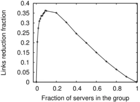
0 0.05 0.1 0.15 0.2 0.25 0.3 0.35 0.4 0 0.2 0.4 0.6 0.8 1
Links reduction fraction
Fraction of servers in the group
Figure 2: Reduction in links used by VM distribu-tion service.
a neighbor that can make progress towards the next corner. If more than one such neighbor exists, then a precedence order over the axes is used to select the next hop, e.g., first
x, thenyand thenz. This completes when the join packet is delivered to a server that is already part of the distribu-tion tree, or is the root. If greedy progress cannot be made towards the next corner, the routing service is used to route to the next key coordinate.
This custom routing protocol reduces the overall number of interior links and servers, as it restricts the set of paths that join requests can traverse. In absence of failures, no path stretch is introduced because packets are always for-warded to servers that are closer to the root key coordinate. We ran an experiment to determine the reduction in the number of links used with the custom routing protocol. We randomly select a key coordinate as the root of the VM distribution tree, and vary the fraction of the servers joining the VM distribution tree. In each run, the servers that join the tree are selected at random. We compare building the tree using the custom routing protocol to using the base routing service. In each case, we measure the number of links that represent edges in the distribution tree.
Figure 2 shows the reduction of links used in the VM service when using the custom protocol versus the fraction of servers joining the group. When the group size is small, e.g. less than 0.01 of the servers in the network, there is little opportunity for sharing links as the servers are picked randomly, so the benefit is small. As the group size increases to 0.1 the benefit increases, as the higher number of group members increases the opportunity for link sharing. As the number of group members increases above this, the benefit decreases again as a higher fraction of the links are used. At the limit, when all servers join the group then there is no benefit in using the modified protocol.
3.3
Cache service
Memory-based soft caches, like the popular memcached, are commonly used in large-scale data centers. They provide a simple API, with insert, read, modify and delete function-ality on key-object pairs. Usually the key is a textual string which encodes information (e.g. user::img::file.jpg) and the object is a string or byte array.
In the design of the cache service, the textual key is hashed and a primary key coordinate derived from the hash, such that the keys are uniformly distributed within the coordi-nate space. As in a DHT, the object is cached on the server responsible for the key coordinate. In order to handle popu-lar keys the caching service also maintains up toksecondary
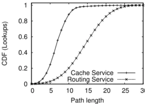
0 0.2 0.4 0.6 0.8 1 0 5 10 15 20 25 30 CDF (Lookups) Path length Cache Service Routing Service
Figure 3: Hops to a cache hit with one primary replica and eight secondary replicas.
replicas of the object. The secondary replicas are generated on demand per key, so the total number of replicas is a func-tion of the popularity of the object. In order to induce better locality, thek secondary replicas are uniformly distributed within the coordinate space. The cache service achieves this by using a function, parameterized on the primary key coor-dinate, the number of secondary replicas (k) and coordinate space size. The function returnsk key coordinates repre-senting the coordinates of each secondary replica.
When a read operation is performed on a key-object pair, the service calculates the primary key coordinate, and the
k secondary replica key coordinates. These are ranked by rectilinear distance from the local key coordinate and the set of closest replicas are selected. If there are multiple closest replicas, and one is the primary replica, then it is selected, else one is randomly selected. The cache service then routes the request via the selected replica key coordinate. If the server responsible for the key coordinate has a copy of the key, then it responds with the associated object and the request is not routed to the primary key coordinate. Oth-erwise, the server forwards the request to the primary key coordinate. If an entry for the key being looked up is found, then this is returned to the original requester via the replica key coordinate. This populates the secondary replica. A cache miss may increase the path length from source to the primary replica, and in the worst case the path would be stretched by a factor of 3. However, the maximum path length, even in case of cache miss, from a source to the pri-mary replica is still bounded by the network diameter.
The caching service uses the default routing service to route between the source and secondary replica, and the sec-ondary replica and primary replica. It also relies on the rout-ing service to remap consistently the key coordinate space on server failure. This is similar to using loose source routing, except the intermediate server address is a key coordinate not a server coordinate, and it does not need to be stored in the packet, as every server on route can determine it using information already in the request packet.
We ran an experiment where the system was populated with 8,000,000 key-object pairs evenly distributed among the servers in CamCube. We performed 800,000 key lookups based on a Zipf distribution (α = 1.5). Each lookup was performed by a server picked uniformly at random (average of 100 lookups per server). We usek= 8 secondary replicas, created on demand as previously described. We compare the performance using the base routing service and the modified routing protocol described. In the routing service version,
the lookup is routed to the primary key coordinate. At each server, before forwarding the lookup, a check is performed to see if a local copy exists. If so, the current server responds to the lookup. Figure 3 shows the CDF of lookup versus path length for both routing protocols. The upper bound in both cases is 30 hops, which is the network diameter. When using the base routing service the median path length is 15, as would be expected, since the probability of encountering a replica by chance on the path is low. With the custom routing protocol, instead, the median path length drops to 7. This means that the median lookup latency is reduced by a factor of 2.
3.4
Aggregation service
The aggregation service is used primarily to support a MapReduce-like [10, 4] application. MapReduce supports data parallel computation. Conceptually a data set is split into M chunks, which are equally distributed across a set of N servers. During the map phase each server applies a map function to each local chunk. This generates a set of key-value pairs per server, where multiple servers can have entries for the same key. The keys are then mapped to a set ofRservers. During the reduce phase each key-value pair is sent to the server to which the key is mapped. The server then combines all the values for the same key, generating a final value for the key. In general, if there areMchunks used in the map phase, andRservers used in the reduction phase, then there will be O(R·M) flows, with M flows going to each of theRservers. Usually a significant number of servers (N) are used, often on the order of thousands. Normally, at leastM =N and, for load balancing and failure resilience, oftenM >> N.
Most MapReduce jobs have multiple entries for each key and, hence, if the reduce function is associative and com-mutative, we can reduce the amount of data transferred by performing on-path aggregation across multiple flows. In-deed, already in MapReduce-like systems, ifM >> N, then on each server the output of the locally executed map func-tions are combined, hence doing aggregation per server.
The aggregation service exploits a customized routing pro-tocol that routes packets from a source server to a destina-tion server coordinate (the reducer) on a deterministic path. This ensures that flows for the same reducer deterministi-cally meet along the path and can be aggregated. The path is made deterministic by fixing each of the axes in turn, so for example, first routing the packet to the correctxplane. Once the x plane has been reached, then routing to the correct y plane, then finally thez plane. This yields a de-terministic path, that in the absence of failures is also the shortest. At each hop, if the link is congested, the service locally buffers the packet until it can be transmitted.
Clearly, if all source servers always route to destinations fixing thex, y, zcoordinate in the same order (e.g.xtheny
and finallyz), then the set of links that can be used will be constrained across instances. To ensure that, whenR >1, allNservers share the load of performing the aggregation we exploit the fact that there are six different orderings possible. To achieve this we hash the destination coordinate, and use these to seed which order we fix the axes.
The customized routing protocol in this service exploits the topology to ensure a good distribution of computational load over the servers. To deterministically select the aggre-gation points, they are considered as key coordinates. If the
Routing Aggregation service service
None Full Total number of links used 19,646 7,999 7,999 Percentage of links used 41% 17% 17% Aggregate packets sent 120,000 120,000 7,999 Median packets (per link) 3 5 1 90th Percentile (per link) 7 9 1 99th Percentile (per link) 51 160 1 Maximum (per link) 1,494 4,000 1
Table 1: Link statistics comparing the aggregation service and routing service.
next aggregation key coordinate cannot be reached using a greedy protocol, the aggregation service uses the routing service to route to the key coordinate. This means that all the packets belonging to a flow are routed through the same server regardless of failures. This provides determinism and is exploited to achieve fault tolerance.
Next, we compare using the customized routing protocol against the routing service. In the routing service case, we route all the packets to a single server that performs the aggregation. Current MapReduce-like systems cannot per-form on-path aggregation. It is hard to perper-form aggregation using the routing service because it exploits multipath at the packet level. This means different packets belonging to the same flow traverse different paths; no single server sees all packets belonging the flow except for the source and destination. In the experiment each server ran a process that generated a single packet containing a key-value pair and sent these packets to a destination server. In one case, (Full), a single key was used across all servers. Hence, two or more packets can always be aggregated into a single packet, and this represents the best case. For the worst case, we also ran an experiment where each server used a unique key in the key-value packet (None). This means that no aggre-gation across packets can be performed and, hence there is no reduction in traffic.
Table 1 reports the number of links and the link stress statistics for using the routing service and the aggregation service with full and no aggregation. Obviously, for the rout-ing service, the statistics are the same whether aggregation is possible or not so we show only one column. Table 1 demon-strates that the aggregation service uses less links in total compared to the routing service; the aggregation service uses deterministic paths and therefore, effectively, restricts the set of paths over which the packets can be routed. In the Full aggregation case, the link load is uniform at one. The max-imum number of packets that any server has to aggregate is seven, and this is at the destination server, assuming that the destination also generates a key-value packet. Clearly, performing aggregation provides considerable benefit. In the no aggregation case both have the same total packet count, as would be expected, but clearly as the number of links used in the aggregation service is lower, the link stress on each of the links is higher. The median and 90th percentile shows a small increase, but it is clear from the max and 99th percentile that a subset of the links sustains a considerably higher load. In the aggregation service, two of the six in-coming links to the destination server sustain the highest and second highest load. The customized routing protocol is designed to provide particular properties, assuming that aggregation is possible. When aggregation is not possible,
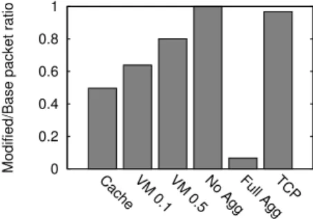
0 0.2 0.4 0.6 0.8 1
Cache VM 0.1 VM 0.5 No AggFull AggTCP
Modified/Base packet ratio
Figure 4: Total packet overhead per service normal-ized by the base routing service.
the customized protocol arguably performs worse than the routing service.
This highlights the need to allow services to select the right routing protocol; one size does not fit all!
3.5
Network-level impact
In the previous part of the section, we have shown that implementing customized routing protocols achieves better service-level properties. Do these customized routing pro-tocols have a negative impact on the network performance? In this section, we consider if the custom protocols tend to induce higher link stress or have very skewed traffic patterns. To evaluate this, we used the same experiments as in the previous section, and measured the aggregate link stress across all links for the experiments with the customized rout-ing protocols and routrout-ing service version. Figure 4 shows, for each service, the ratio between the total packets sent us-ing routus-ing service and the customized routus-ing protocols. A value less than one means that the customized routing proto-col generated less network overhead compared to the routing service version. It should be noted that for the VM distri-bution service we compare two points, when 10% (VM 0.1) and 50% (VM 0.5) of the servers join the group. Further, for the VM distribution service we are measuring the over-head of tree building, but when distributing a VM through the tree, the same packet saving will hold. The results in Figure 4 show that in all cases the overhead induced by the customized routing protocol is lower, and is therefore, ben-eficial. It might seem counter-intuitive that the TCP/IP service achieves a higher throughput with a lower packet overhead. However, in the base routing protocol the source has to retransmit packets that are dropped due to conges-tion induced by overlapping paths, which increases packet overhead. In contrast, the custom routing protocol used by the TCP/IP service ensures that packets are routed on dis-joint paths and, hence, it does not incur congestion and no packets are retransmitted.
In order to understand if we were inducing significantly higher link stress on each link, we looked at the distribution of link stress. We ranked the links in ascending order, exam-ining the 99th percentile and maximum. In both measures, the aggregation service in the no aggregation case performed significantly worse than the routing service, over 2.5 times higher. However, for the full aggregation case, and for all other services, the link stress was equal or lower.
All the results so far have ignored any maintenance over-head induced by the customized routing protocols. The
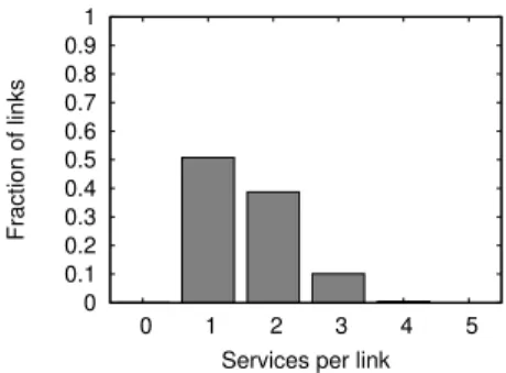
0 0.1 0.2 0.3 0.4 0.5 0.6 0.7 0.8 0.9 1 0 1 2 3 4 5 Fraction of links
Services per link
Figure 5: Fraction of links versus number of services.
routing service uses a link-state routing protocol and gener-ates overhead whenever links fail. However, one interesting aspect of all the other routing protocols is that none of them have any explicit maintenance overhead, and simply exploit the properties of the coordinate space to obtain the property that they want. The reason that the routing service uses a link-state protocol is to enable it to continue routing when failures occur, when a greedy coordinate-based approach will fail. All the other protocols use the routing service in such circumstances, which allows them to avoid the need to have their own maintenance traffic.
We have been considering each service in isolation. The customized routing protocols could have some correlated way in which they use links, which would yield poor perfor-mance when they operate concurrently. We ran an exper-iment to understand if these four protocols described here interfere. We ran all four services and examined the link sharing across services. For the aggregation service we had all servers sending a packet to a single root. For the caching service each server looked up the same object. For the VM distribution server we had 50% of the servers in the distri-bution tree, and for the TCP/IP service we had 1,000 server pairs transmit data.
We determined how many of the services had used each link. So, for each link we generated a value between zero and four. Figure 5 shows the distribution of the links versus the number of services that used the link. This allows us to see the general trend of whether the services are all using the same subset of links, as the absolute number of packets per link is dominated by the TCP/IP service. The results show that the majority of links are used by a single service, and there are few links used by three or more services. This indicates that, in this set of custom protocols, we are not seeing a general preference for a particular subset of links.
4.
PROPERTIES
Next, we identify a number of properties that underpin the routing protocols described, which are used to motivate the design of an extended routing service, that allows services to easily develop their own.
Key coordinate versus server coordinate Many ser-vices use the routing service for key-based routing. This exploits its ability to deterministically manage the mapping of keys to servers. However, some services also need server-based routing.
Path specification The path from a source to destination is often via one or more specified intermediate (x, y, z) coor-dinates. However, rarely is the full path specified, most
ser-vices just use a small set of intermediate coordinates through which packets must traverse. The routing service routes be-tween the intermediate coordinates. This provides function-ality similar to loose source routing.
Fault-tolerance Many services use greedy-based proto-cols, which exploit the coordinate space. A key challenge for greedy protocols is to make them resilient to failures which, in corner cases, can cause voids in the static coordi-nate space used in CamCube, as described in Section 2.1.2. As voids are rare the services do not implement their own mechanism to handle them, but rely on the routing service which is able to route around any voids. This avoids adding complexity to the services. This is also beneficial in terms of network load, as each service does not need to generate any maintenance traffic. The services leverage the state main-tained by the existing routing service.
Multipath The 3D torus topology provides multiple paths between servers. Some services exploit this path diversity to increase the end-to-end throughput and to avoid congested links. Other services require all packets in the same flow be routed through the same set of servers, for example in the aggregation service.
Packet buffers Services have different requirements for packet buffer sizes. Small buffers generate packet loss in the presence of congestion whereas large buffers incur queuing delay which increases end-to-end latency. All services use end-to-end reliability mechanisms but some also use per-hop mechanisms. These services tend to buffer packets for long periods, depending on the service from seconds to hours. Prioritization We have a few services that prioritize traf-fic, e.g., the routing service prioritizes control packets over data packets. We believe many more services could benefit from this, but the current complexity means it is normally only added in when it fixes an observed problem.
5.
EXTENDED ROUTING SERVICE
Next we describe the extended routing service, which aims to make it simple for services to specify their own routing protocols. Services that use the routing service are expected to provide a per-service functionF that operates in the co-ordinate space and defines a set of key coco-ordinates through which packets are routed. Services also provide a policy that controls queuing of packets for the service. The exist-ing routexist-ing service is split into two components: one that provides failure information, and a forwarding engine that forwards messages towards a specified key coordinate.
Services register with the routing service to use it. A registering service provides the functionFto be used and the queue policy parameters. In the simplest form the functionF
is a function that returns the destination key coordinate, and the only queuing parameter required is the queue length (in milliseconds) and is the upper bound on the time that any packet can be queued locally. When a service registers with the routing service, the routing service registers, on behalf of the other service, with each link. Recall that a polling mechanism is used per link to obtain packets to transmit.
When a service, S, wishes to route a packet, it creates the packet and hands it to the routing service. The routing service calls the instance of F associated with S, passing in the packet. The role of functionF is to return a set of possible next key coordinates (K) in the coordinate space,
K={k1, k2, . . . , kn}. The functionF operates in the coor-dinate space with the assumption that if the returned key
coordinates correspond to a failed server, then the forward-ing engine will remap them. Hence, the packet will be routed towards a server responsible for one of the coordinates inK. Note that the functionF does not return the entire set of key coordinates through which the packet should be routed, just the next possible key coordinates. Further, the next key coordinate could be mapped to a physical one-hop neighbor of the current server, it could be mapped to a server that is multiple hops from the current server, or indeed, due to failures, the next key coordinate could be mapped onto the current server. As the functionF works in the key coor-dinate space, when invoked, it needs to determine the key coordinate for which theF is being performed. When there are no failures then this will be the local server coordinate. However, in the presence of failures the coordinate may not be the same as the local servers coordinate. The functionF
is able to access local state information maintained within
S, as well as information within the packet and information from the failure component.
When the routing service has determined the setK, the packet is then queued to be sent out on a link. The routing service maintains a separate queue per-service. When the routing service is polled for a packet by a link L forS, it checks the packets queued forS, in order, to see if any packet can go out onL. It does this by checking if the shortest path to any of the key coordinates inKgoes throughL, provided that the packet was not received from the server connected onL. Before transmitting, the destination of the packet is set to the key coordinate that matched inK. IfLis on the shortest path for multiple entries inKthen one is randomly selected from this subset.
When a packet is received by a server, it is delivered to the service identified byserviceId, not the routing service. This allows CamCube to easily perform fine-grained accounting of resources on the server and, also enables a service to in-spect (and modify) that packet. For instance, in the VM distribution service, at each physical hop a request to join a group is checked, and if the local server is already part of the tree, the request is locally handled and the request is not for-warded further. The VM service internal state is updated to reflect that a new child has been added. However, normally, most services simply pass the packet to the routing service. The routing service determines if the local server is responsi-ble for the current destination key coordinate and, if so, the functionF is called. This will generate a set Kcontaining the set of possible next key coordinates. If the current server is not responsible for the current destination key coordinate, then the routing service simply takes the current destination key coordinate and queues the packet on service’s queue. If a link on the shortest path to the destination key coordinate polls the service, and no older packets can be transmitted on the link this packet is transmitted, again provided it was not delivered from the server on that link.
In some cases, the F function may need to create ad-ditional copies of a packet and forward them to different intermediate destinations. For example, in the VM distri-bution service, when a packet is distributed along the tree, if a server has more than one child, the packet must be repli-cated for each child. This is accomplished by means of a function transmit that takes as arguments the packet to send and the corresponding setK.
Much of the power of the approach is enabled through theF function. In Section 7 we will look in detail at how a
number of routing protocols use it. However, most services simply use the F function to return a single intermediate coordinate. For instance, in the aggregation service, this is the key of the next point in the coordinate space to perform aggregation. However, F can also return more than one possible intermediate destination, as in the TCP/IP service. Finally, a powerful component of the extended routing service is the way in which it handles queues. Earlier we observed that it was harder for service designers to incorpo-rate classes of traffic with different priorities. To make this easier, the extended routing service allows multiple queues to be maintained per service. A service can then map pack-ets, or flows, onto a particular queue. To enable this, each service is required to provide a functionclassify that takes a packet and returns a queue identifier. There is a default queue which is created when the service first registers with the extended routing service. In the simple case, the func-tion classify always returns the default value. However, if traffic differentiation is required, then the function classify
can capture this by returning different queue identifiers. If the queue identifier is new then the service also has to pro-vide the maximum time for which a packet can be queued in the queue and a per-queue weighting. The extended routing service, per service, implements a simple weighted fair queu-ing mechanism across the queues belonging to the service. Across services, we use a simple fair queuing mechanism. The intuition is that internally within a service prioritizing traffic is easy, requiring just the service writers to under-stand their requirements. In contrast, across services, even in an environment where all services are cooperative, us-ing a weighted scheme requires understandus-ing the relative importance of services. Our initial experiences lead us to believe that doing this across services introduces significant complexity. This is compounded when most services are, by design, oblivious to the other services running.
6.
PERFORMANCE EVALUATION
To evaluate the performance overhead of the extended routing service, we experimented with our CamCube testbed. The testbed consists of 27 servers. The direct-connect net-work has 3 servers on each axis, creating a 3x3x3 cube. Each server is a Dell Precision T3500 with a quad-core Intel Xeon 5520 2.27 GHz processor and 4 GB RAM, running an un-modified version of Windows Server 2008 R2. We equip each server with one 1 Gbps Intel PRO/1000 PT Quadport NIC and two 1 Gbps Intel PRO/1000 PT Dualport NICs, in PCIe slots. One port of the four port card is connected to a dedi-cated 48-port 1 Gbps NetGear GS748Tv3 switch. This pro-vides the switch network giving external connectivity to the CamCube. Six of the remaining ports, two per multi-port NIC, are used for the direct-connect network. The extended routing service only routes traffic only on the direct-connect topology. The Intel NICs support jumbo Ethernet frames of 9,014 bytes (including the 14 byte Ethernet header). In the experiment we use jumbo frames and use default settings for all other parameters on the NICs.
We ran two experiments, abase experiment, where the six one-hop neighbors of a serverSattempt to saturate the 1 Gbps link from them to S. S runs a simple service, that when it receives a packet from a one-hop neighbor it simply bounces the packet back to the neighbor. This represents a service that forwards packets, and the per-packet overhead is the lowest that can be achieved. We also ran an
0 5 10 15 20 25 30
Baseline 1 key 2 keys 3 keys
CPU Utilization (%)
Figure 6: CPU overhead for baseline and extended routing services with|K|=1,2 and 3.
ment, theextendedexperiment, with a service that uses the extended routing service. Again, the six neighbors ofSsend packets at line rate toS, but they specify the destination as a key for whichSis responsible. However, the neighbors also generate a set ofqrandom keys which map onto themself, and insert them into the packet. Sthen runs a service which uses the extended routing service, and has a functionFthat extracts the keys from the packet, and then returns the set of keys embedded in the packet as the next coordinates,K. In the extended routing service the cardinality ofK domi-nates the CPU overhead. We observe that in the majority of services implemented to date that cardinality ofK(|K|) is usually one or two. We therefore, run the experiment for
q= 1,2 and 3, where|K|=q.
For each experiment we record the aggregate throughput in Gbps and the CPU utilization at serverS. The aggregate throughput excludes the Ethernet headers, but includes the CamCube service header. We measure the CPU utilization by using Windows performance counters which provide, per core, an estimate of the CPU utilization as a percentage. As we have quad core processors, with hyper-threading, we obtain eight CPU readings. We then calculate the average CPU utilization across all eight and use that as the utiliza-tion per server. We observe that the CPU utilizautiliza-tion is not skewed across the cores.
The aggregate throughput achieved in the baseline case was 11.88 Gbps, and given that each server is using six 1 Gbps links there is a theoretical upper bound of 12 Gbps. When using the extended routing service we observe less than a 0.9% loss in maximum throughput between based line and when|K|= 3. Figure 6 shows the CPU utilization, for the base line as we vary |K|. These results show that in the baseline case the CPU utilization is 22.01%, and this rises to 25.35% when |K| = 3. These results demonstrate the low overhead that the extended routing service induces.
7.
USING THE ROUTING SERVICE
When evaluating the extended routing service it is hard to make strong claims about its expressiveness. However, we have successfully re-implemented all our routing protocols in the extended routing service and achieved performance comparable to the original versions. In this section we briefly discuss theF functions for all the services described in this paper, and provide a detailed example of the F function used in the VM distribution service, which represents the most complex routing protocol used.
We provide a number of support functions:
dist(coordA, coordB): returns the rectilinear distance be-tween two coordinates, e.g. dist((1,1,1),(0,0,0)) = 3;
distAxis(coordA, coordB, a): returns the distance of the two coordinates relative to axisa, e.g.,distAxis((1,1,1),(2,3,4), x) = 1;
getCoordN eigh(coord, a, dir): returns the key coordinate of the neighbor of coord that lies on axis a, in the direc-tion specified by dir, e.g., getCoordN eigh((0,0,0), y,1) = (0,1,0).
TheF function of the cache service is straightforward. At the source of a lookup,F determines the key coordinate of the object to be retrieved and returns the set of key coordi-nates of the closest replicas, utilizing thedistfunction. The routing service will route the packet to the server responsible for the selected key coordinate. When the packet reaches the key coordinate, the cache service checks whether the object has been cached locally and, if so, the packet is discarded and a copy of the object is returned to the source. Other-wise,Fis re-evaluated on the packet, and will return the key coordinate of the primary replica as the next destination.
TheF function for the aggregation service defines a de-terministic path through the key coordinate space. The function greedily attempts to minimize the distance on each axis, obtained throughdistAxis, by continuously selecting a neighbor key coordinate on that axis that is closer to the fi-nal destination key coordinate. The order in which the axes are used is a function of the hash of the key coordinate of the final destination.
TheF function used by the TCP/IP service at the source returns the key coordinates of all one-hop neighbors, except those that are on the same axis, but in the opposite direc-tion, of the one-hop neighbors lying on the shortest paths. Then, at the next hops,F returns the key coordinate of the one-hop neighbor that is on the same axis of the neighbor from which the packet was received, if this is closer to the destination. Otherwise, it deterministically selects another axis and routes the packet to the neighbor on that axis that is closer to the destination. This raises an interesting exam-ple of the relationship between key coordinates and server coordinates. The F function returns key coordinates. In the event of a server failure, this may cause packets to be delivered to the server to which the key coordinates of the failed server have been assigned. The TCP/IP service on that server will drop the packet.
As a more elaborate example, Figure 7 provides pseudo-code for theFfunctions used by the VM distribution service. In this service, we have two different type of packets: join
packets, which are used to construct the tree, anddata pack-ets, which contain the chunks of the file being distributed.
When a server wishes to become a member of the distribu-tion tree, it issues a new join packet and forwards it towards the root, following the protocol detailed in Section 3.2. At each hop, the VM distribution service intercepts the join packet. The key coordinate of the neighbor from which the packet was received is added to the set of child nodes (C). Then, if the local server is already part of the tree or it is the root, the packet is dropped. Otherwise, the packet is handed to the extended routing service to continue forward-ing it towards the root.
TheF function used to forward join packets is shown in Figure 7(a). It recursively partitions the coordinate space into smaller mini-cubes. To route to the root coordinate of the VM distribution tree, it traverse the corners of the
1: min l← ∞
2: for allaxis∈ {x, y, z}do
3: ifCurrKeyaxis6=Rootaxisthen 4: l←log2E−1
5: whiledistAxis(CurrKey, Root, axis) mod 2l6= 0do
6: l←l−1
7: ifl < min lthen 8: min l←l 9: min axis←axis
10: upN←getCoordN eigh(CurrKey, min axis,1)
11: downN←getCoordN eigh(CurrKey, min axis,−1)
12: ifdist(upN, Root)< dist(downN, Root)then 13: return {upN}
14: else
15: return {downN}
(a) Join packets. 1: for allc∈ Cdo
2: transmit(p,{c})
3: return
(b) Data packets.
Figure 7: Pseudo-code for theFfunctions of the VM distribution service to handle join and data packets.
hierarchical mini-cubes. In the pseudo-code we indicate with
CurrKeythe key coordinate for whichF is being performed and withRootthe key coordinate of the root. These are all included in the packet. Finally,coordx,coordy and coordz denote the value of thex,y, andz elements of coordinate
coord, andEdenotes the length of the edge of the cube. For simplicity, we assume thatE= 2kwithk >0.
The first stage is forFto determine the levellofCurrKey
in the mini-cube hierarchy (lines 2–9). Intuitively, the size
S of the edge of the largest mini-cube that has a vertex in
CurrKey is equal to 2l. For example, ifCurrKey is at the bottom of the hierarchy, i.e., l = 0, we have that S = 1. Dually, ifCurrKey is a vertex of one of the eight top-level mini-cubes, thenS =E2 = 2k−1. The value ofScan be com-puted by observing that on each axis the distance between
CurrKeyand the root (obtained throughdistAxis) must be an exact multiple ofS. Therefore,F iterates over each axis and recursively halves the length of the mini-cube edge un-til it exactly divides the distance fromCurrKeyto the root key coordinate along that axis (lines 5–6). This indicates the level in the hierarchy for that axis. The lowest level across all axes represents the level ofCurrKeyin the hierarchy. At line 10,F has successfully identified the level ofCurrKeyin the hierarchy and the axis with the lowest level in the hier-archy. This is contained in the variablemin axis. F then greedily selects the neighbor in the key space that is closer to the root and returns it as next intermediate destination (lines 10–15).
This function is used to perform tree construction and dur-ing the multicast phase the simpler function in Figure 7(b) is used. This simply forwards a copy of received packets to the children.
8.
RELATED WORK
Networking infrastructure in data centers, including re-cent research proposals [2, 16, 25], is influenced by tra-ditional Internet architectures and standards. Packets are routed through switches or routers and end-hosts have
lit-tle control on routing decisions. A single routing protocol is provided to applications. Simple policies, like having an application’s traffic go through a middlebox, are hard to support [21]. In general, the IP protocol allows end-systems to influence the path by using loose source routing. This, however, is not widely supported due to the overhead of maintaining network topology state at the end-systems and the packet overhead of carrying the information. Propos-als to address these issues, for example [23, 30, 31], provide coarse-grained control to the end-hosts or edge ISPs. Our approach can be seen as a similar to loose source routing, with routes specified in terms of keys. However, the path keys are computed dynamically rather than statically en-coded in the packet. More generally, multi-service switched networks [26] support multiple routing protocols on a single physical network. In this approach, referred to as ships in the night, routing protocols use separate control planes and no state is shared among them. The work described here aims to allow the routing protocols to share information, in order to minimize control traffic.
Current data centers can exploit multi-path using network-level configuration, for example using equal cost multi-path protocol (ECMP) to balance flows across multiple paths. They operate at a flow level to avoid packet reordering, which would impact TCP. Centralized flow schedulers have been proposed to allow more efficient network utilization [3] and to enable energy savings by switching off redundant links [19]. These schedulers are traffic agnostic. The work proposed here allows services to individually specify and con-trol the routing protocol that they use. Direct-connect [7] and hybrid topologies [18, 17], where servers participate in packet forwarding, have recently been proposed, as de-scribed in Section 2. All provide a default routing protocol, and in the case of BCube and DCell this runs transparently beneath the TCP/IP stack. Hence, applications running on them have limited ability to exploit the fact that packets are routed through servers. CamCube, and the flexibility that it provides by having a low-level API that explicitly exposes the packets to services as they are routed through servers enables services running on CamCube to exploit this. It would be feasible to use some of the ideas of enabling mul-tiple routing protocols on these other platforms.
Direct-connect topologies have been widely used in the context of High Performance Computing (HPC) [11], e.g. the IBM BlueGene and Cray XT3/Red Storm use a 3D torus. They use variants of greedy geographic routing pro-tocols [29, 1], and normally only tolerate small-scale failures, for example, the IBM BlueGene/L tolerates only three server failures [1]. It has been proposed to increase fault-tolerance by running multiple routing protocols [27], a primary and a secondary, where the secondary routing protocol is used only when the primary cannot make progress due to server fail-ures. HPC systems often use MPI [24] as the communication API, which isprocess rather thanserver based. The com-piler and job scheduler control the mapping between pro-cesses and servers. MPI utilizes the path and multi-hop routing offered by the platforms but, therefore, cannot exploit on-path interception and modification of packets.
The IBM Kittyhawk Project [5] evaluates using the IBM BlueGene/P for data center workloads. They provide a flat layer 2 IP network running over the 3D torus network, hid-ing the different topology. In contrast, CamCube explicitly
exposes the underlying topology to the services, which then exploit it.
9.
CONCLUSIONS
We have explored the benefits and feasibility of using mul-tiple service-specific routing protocols in a data center of the future. We have done this in the context of the CamCube architecture, which uses a 3D torus topology, where each server directly connects to six other servers. We are target-ing shipptarget-ing container-sized data centers, and do not require the use of any switches or dedicated networking within the container. We are currently utilizing a low-level link orien-tated API in CamCube, which provides the flexibility for services to implement their own routing protocols.
We have demonstrated that the individual services can ob-tain better application-level performance by utilizing their own protocols, and that at the network level this can also provide better performance. For all services the network load is reduced when the service uses its own optimized pro-tocol. This led us to extend our routing service to allow services running on CamCube to easily implement their own routing protocols.
10.
ACKNOWLEDGMENTS
We thank the reviewers, and in particular our shepherd, Jen-nifer Rexford, who provided valuable feedback and advice. Hussam was supported in part by AFOSR grant FA9550-06-1-0019, AFRL grants FA8750-09-1-0003, FA8750-08-2-0153, FA8750-09-1-0209, and NSF grants 0424422 and 0828923.
11.
REFERENCES
[1] N. R. Adiga, M. A. Blumrich, D. Chen, P. Coteus, A. Gara, M. E. Giampapa, P. Heidelberger, S. Singh, B. D. Steinmacher-Burow, T. Takken, M. Tsao, and P. Vranas. Blue gene/l torus interconnection network.
IBM Journal of Research and Development, 49(2), 2005.
[2] M. Al-Fares, A. Loukissas, and A. Vahdat. A scalable, commodity data center network architecture. In
SIGCOMM, 2008.
[3] M. Al-Fares, S. Radhakrishnan, B. Raghavan, N. Huang, and A. Vahdat. Hedera: Dynamic Flow Scheduling for Data Center Networks. InNSDI, 2010. [4] Apache Hadoop.http://hadoop.apache.org. [5] J. Appavoo, V. Uhlig, and A. Waterland. Project
Kittyhawk: building a global-scale computer: Blue Gene/P as a generic computing platform.SIGOPS Operating Systems Review, 42(1), 2008.
[6] F. Chang, J. Dean, S. Ghemawat, W. C. Hsieh, D. A. Wallach, M. Burrows, T. Chandra, A. Fikes, and R. E. Gruber. Bigtable: A Distributed Storage System for Structured Data. InOSDI, 2006.
[7] P. Costa, A. Donnelly, G. O’Shea, and A. Rowstron. CamCube: A Key-based Data Center. Technical Report MSR TR-2010-74, Microsoft Research, 2010. [8] F. Dabek, B. Zhao, P. Druschel, J. Kubiatowicz, and
I. Stoica. Towards a common API for structured P2P overlays. InIPTPS, Feb 2003.
[9] F. Dabek, B. Zhao, P. Druschel, J. Kubiatowicz, and I. Stoica. Towards a common api for structured peer-to-peer overlays. InIPTPS, 2003.
[10] J. Dean and S. Ghemawat. MapReduce: Simplified Data Processing on Large Clusters. InOSDI, 2004. [11] J. Duato, S. Yalamanchili, and L. Ni.Interconnection
Networks: An Engineering Approach. Elsevier, 2003. [12] S. Durocher, D. Kirkpatrick, and L. Narayanan. On
routing with guaranteed delivery in three-dimensional ad hoc wireless networks. InICDN, 2008.
[13] B. Fitzpatrick. Distributed caching with memcached.
Linux Journal, 2004(124), 2004.
[14] S. Ghemawat, H. Gobioff, and S.-T. Leung. The Google File System. InSOSP, 2003.
[15] D. Giuseppe, H. Deniz, J. Madan, K. Gunavardhan, L. Avinash, P. Alex, S. Swaminathan, V. Peter, and V. Werner. Dynamo: Amazon’s Highly Available Key-value Store. InSOSP, 2007.
[16] A. Greenberg, J. R. Hamilton, N. Jain, S. Kandula, C. Kim, P. Lahiri, D. A. Maltz, P. Patel, and S. Sengupta. VL2: A Scalable and Flexible Data Center Network. InSIGCOMM, 2009.
[17] C. Guo, G. Lu, D. Li, H. Wu, X. Zhang, Y. Shi, C. Tian, Y. Zhang, and S. Lu. BCube: A High Performance, Server-centric Network Architecture for Modular Data Centers. InSIGCOMM, 2009.
[18] C. Guo, H. Wu, K. Tan, L. Shiy, Y. Zhang, and S. Luz. DCell: A Scalable and Fault-Tolerant Network Structure for Data Centers. InSIGCOMM, 2008. [19] B. Heller, S. Seetharaman, P. Mahadevan,
Y. Yiakoumis, P. Sharma, S. Banerjee, and N. McKeown. ElasticTree: Saving Energy in Data Center Networks. InNSDI, 2010.
[20] M. Isard, M. Budiu, Y. Yu, A. Birrell, and D. Fetterly. Dryad: distributed data-parallel programs from sequential building blocks. InEuroSys, 2007. [21] D. A. Joseph, A. Tavakoli, and I. Stoica. A
policy-aware switching layer for data centers. In
SIGCOMM, 2008.
[22] B. Karp and H. Kung. GPSR: Greedy Perimeter Stateless Routing for Wireless Networks. InMobiCom, 2000.
[23] M. Motiwala, M. Elmore, N. Feamster, and S. Vempala. Path splicing. InSIGCOMM, 2008. [24] MPI Forum.http://www.mpi-forum.org. [25] R. Niranjan Mysore, A. Pamboris, N. Farrington,
N. Huang, P. Miri, S. Radhakrishnan, V. Subramanya, and A. Vahdat. Portland: a scalable fault-tolerant layer 2 data center network fabric. InSIGCOMM, 2009.
[26] C. Pignataro, R. Kazemi, and B. Dry.Cisco Multiservice Switching Networks. Cisco Press, 2002. [27] V. Puente and J. A. Gregorio. Immucube: Scalable Fault-Tolerant Routing for k-ary n-cube Networks.
IEEE Trans. Parallel Distrib. Syst., 18(6), 2007. [28] S. Ratnasamy, P. Francis, M. Handley, R. Karp, and
S. Shenker. A Scalable Content-addressable Network. InSIGCOMM, 2001.
[29] S. L. Scott and G. Thorson. Optimized Routing in the Cray T3D. InPCRCW, 1994.
[30] W. Xu and J. Rexford. Miro: multi-path interdomain routing. InSIGCOMM, 2006.
[31] X. Yang and D. Wetherall. Source selectable path diversity via routing deflections. InSIGCOMM, 2006.