Interference Mitigation for a joint radar
communication system based on the FrFT for
Automotive Applications
Pasquale Striano, Christos V. Ilioudis, Jianlin Cao, Carmine Clemente, and John J. Soraghan
Centre for Signal and Image Processing, University of Strathclyde, Glasgow, United KingdomEmail: pasquale.striano, c.ilioudis, jianlin.cao, carmine.clemente, j.soraghan- @strath.ac.uk
Abstract—In multi user scenarios to prevent interference between users that share the same bandwidth at the same time, each user has to transmit waveforms that are uncorrelated with those of other users. However, due to spectrum limitations, the uncorrelated property cannot always be satisfied meaning that interference is unavoidable. In order to alleviate the interfer-ence, a framework for interference mitigation is presented. The performance of the proposed framework is tested on simulated and real signals. The real signal is acquired in a controlled laboratory environment using a Software Defined Radio (SDR). The simulated and experimental results show that the proposed framework is capable of mitigating the interference from other users.
I. INTRODUCTION
The safety of vehicle and passenger is the prime objective of the Advanced Driver Assist Systems (ADAS). The auto-motive radar based ADAS is used to detect and calculate the range, velocity, and positioning of the approaching vehicles and to notify the driver in case of any blindspot hazards. Moreover, a Vehicle to Vehicle communication (V2V) sys-tem is also used, where the vehicles share information such as position data, vehicle speed data or radar data with nearby vehicles.
The separation of the radar and communication functions are not efficient since both of them require their own frequency resources. One solution to the problem is to develop a joint radar communication system that uses the same waveform, frequency and hardware to perform both operations at the same time.
In [1] a new joint radar communication system based on the Fractional Fourier Transform (FrFT) was proposed. It was shown that the radar performance in terms of the Ambiguity Function (AF) and Side Lobe Levels is similar to the Linear Frequency Modulation (LFM) waveform. How-ever, this framework does not fit the standards of automotive radar as it employs pulsed waveforms. In automotive radar, the Frequency Modulated Continuous Waveform (FMCW) is commonly employed due to the advantages of Continuous Waveform (CW) and LFM waveform allowing continuous transmissions and ranging capabilities [2].
In [3] and [4] a joint radar communication system based on the FrFT for automotive environment was presented. The waveforms are transmitted in a consecutive manner similar to the Fast Chirp FMCW (FCFMCW) [2]. In [3] it was
shown that the radar performance of the proposed system is not significantly dependent on the data information that are embedded in the radar waveform. Additionally, in [4] it was shown that this framework can work in different environments ensuring a good Bit Error Rate (BER). While in [5] it was shown that the proposed framework fits in a multi user scenario.
In an automotive environment, where multiple users are in close proximity to each other and moreover these op-erate in the same frequency band, consequently, mutual interference may arise. For an ADAS application, a high probability of detection is required, consequently, the mutual interference represents an issue because it leads to problems as degradation of the detection performance or/and sensors blindness [6]. In the literature different types of algorithms were proposed to improve the detection performance when interfering signals are present. These algorithms can be divided into two general classes, the first class includes algorithms based on detection or identification of interfer-ence before mitigating it [7], [8], [9], while the second class includes techniques where the interference is mitigated without detecting or identifying it [10].
In [11] and [5] two frameworks for interference mitigation were proposed, with the interference signal being recon-structed and then subtracted from the received signal. The performance of these two frameworks is highly dependent on the correct estimation of the frequency. A small error on the frequency can lead to a lack of synchronization between the received and reconstructed signal. Consequently, the subtraction will be not performed in a correct way and further interference components can be introduced.
In this paper, a new framework for interference mitigation is proposed. The main contribution of this work can be summarised as: the estimation of the power of the received interference is obtained by applying a matched filter between the received waveform and reconstructed interference. Addi-tionally, to improve the performance even in scenarios where the frequency offset is not perfectly estimated the subtraction is carried out between the absolute values of the processed radar signal and the reconstructed interference representa-tions. After this framework the phase of parameters is lost, consequently, only the processing that takes into account the intensity of parameters can be applied as Constant False
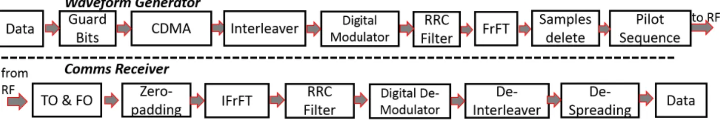
Fig. 1: Block diagram of (top) the mono-static radar and (bottom) the Communication Receiver of the FrFT based on a joint radar-communication basic configuration.
Alarm Rate (CFAR) and/or Neural Networks (NN). The performance of the proposed framework is evaluated by considering three scenarios: in the first two scenarios the radar transmitter is switch off, so the radar receives only the signal from the interference user. In the first scenario the performance is evaluated on a simulated signal without noise, while in the second scenario, the interference mitigation is applied on real data acquired using a Software Defined Radio (SDR). Finally, in the third scenario the radar transmitter is on and a target is present.
The remainder of the paper has the following struc-ture. Section II summarises the concept of the FrFT. In Section III the proposed radar communication receiver is presented while Section IV describes the framework for interference mitigation. In Section IV the framework is analysed by means of simulated interference signals. Section VI describes the acquisition geometry of the laboratory-based experiments, while in Section VII the framework is evaluated with the real data. Section VIII draws conclusions.
II. FRACTIONALFOURIERTRANSFORM
The Fractional Fourier Transform (FrFT) [12], is a gen-eralization of the Fast Fourier Transform (FFT) , it can be interpreted as a rotation in the time-frequency plane by an angle φ with time axes. The FrFT of a functionx(t), with an order α= 2πφ, is defined as, [13] :
Xα(u) =Aαe(iπBαu 2)Z ∞ −∞ x(t)eiπBαt2e−i2πCαutdt (1) where Aα=
e(−iπsgn(sinφ)/4+iφ/2)
|sinφ|1/2 (2)
with i being the imaginary unit, sgn the signum function, while Bα andCα are:
Bα= cot π 2α , Cα= csc π 2α (3) The industry is developing a framework to calculate the FrFT for an automotive radar.
III. WAVEFORMDESIGN
In this section the waveform generation scheme for the proposed joint radar communication system is presented. The waveform design chain is shown at the top of Fig.1. Starting from the data to be transmitted, for N bits of information, G guard random bits are added at the end
of the sequence in order to compensate the group delay introduction from the Root Raised Cosine (RRC) filter [14]. In an automotive environment several transmitters send information simultaneously over a single channel, hence multiple users share the same bandwidth. To allow this without undue interference between users a Code Division Multiple Access (CDMA) is used, where each user uses a different code to modulate their data. In this system a Pseudo Noise (PN) code is proposed. After the channel coding,L redundant bits are added; leading to a spread sequence of
(N +G)L bits. Additionally, to spread the burst of the errors across the entire sequence the interleaver is used, applied only to theNbits. Finally, the bits of information are modulated using a Binary Frequency Shift Keying (BFSK). In this modulation scheme binary information is transmitted using two discrete frequencies, with a separation fsep.
Additionally, this scheme assignsNsnumber of samples per
symbol, leading to(N+G)LNslong samples sequence. The
RRC filter is used to minimise the Inter-Symbol Interference (ISI) that may be caused by the channel. The RRC filter is characterised by two values: roll off factor β which determines the bandwidth of the spectrum, and Filter Span in Symbols which truncates the impulse response to aSvalue. For efficiency, it is implemented as a multirate filter that up-samples the output by a factorRs. The final sequence is then
composed by U = (N +G)LNsRs samples. It is noted
that all these functions are commonly used in a standard communication systems. At this point, the signal is rotated in time-frequency domain with a specific orderαusing the FrFT.
In multi user scenarios, to distinguish between emissions from different users each user has to transmit waveforms that are uncorrelated from each other users. In [3] it was demonstrated that the radar performance in terms of AF and Side Lobe Levels of the proposed waveform is similar to that obtained using LFM and consequently in the proposed scheme multi user operations are possible by assigning a specific order of the FrFT to each user. In this way, it is possible to allocate more than one user in the same bandwidth at the same time ensuring a low interference. Furthermore, the CDMA is also used to ensure low level of mutual interference between different users accessing at the same channel.
When the order of the FrFT moves from 0 to 1, the energy of the low-pass signal concentrates in the middle of the
pulse and very low intensity samples appear at the beginning and end of the pulse [4]. To keep the transmitted power at near consistent level and to get a continuous waveform, a threshold is applied to remove those low intensity samples. The Coherent Processing Interval (CPI) of the proposed waveform design has a similar time-frequency profile with an FCFMCW signal as presented in [4] and [5]. In order to increase the Signal to Noise Ratio (SNR) and therefore improve the radar performance, the same bits of information are embedded in every waveform in a CPI, meaning that the data information change from CPI to CPI. A pilot sequence is also transmitted. The pilot is given by the sum of two pulses obtained by applying two different orders of the FrFT, α and −α, on a baseband signal with amplitude equal to one and zero phase [15]. Such pilot can be used by the communication receiver to estimate the time and frequency offset of the received signal. Moreover, the pilot sequence is used as an identification to discriminate between different users/transmitters. To achieve this each user generates a pilot sequence with the same order αused to map the data information into the radar waveform. For the radar part, the target parameters estimation are obtained by applying a matched filter and a Doppler processing as described in [5].
A. Receiver
In the bottom of Fig. 1 a block diagram of the commu-nication receiver is illustrated. In the first step, two FrFTs of order Q1 = 1−α and Q2 = −(1 −α) are used to
perform the synchronization by estimating the frequency and time offset as described in [15]. Once the synchronization has been performed by mitigating the appropriate time and frequency offset, the waveform can be demodulated. The length of the input of the Inverse FrFT (IFrFT) must be equal to the length of the signal after the FrFT in transmission. For this reason, a zero-padding is applied at the beginning and at the end of the received signal. After the zero padding, the sequence enters in the IFrFT block to perform the inverse FrFT. The sequence is then passed through an RRC filter by a factor Rs, and the digital demodulator that translates the
sequence of symbols in a sequence of bits. At this point, a de-interleaver performs the inverse of the interleaver. Finally, to recover theN bits of the information a despread is applied on the received signal, using the same code that was used to spread the data.
IV. INTERFERENCEMITIGATIONFRAMEWORK In this framework, multi user operations are allowed by assigning a specific order of the FrFT to each user. In [4],
Fig. 2: Block diagram of the interference mitigation.
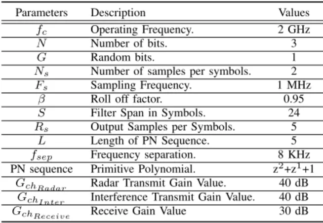
TABLE I: System Parameter
Parameters Description Values fc Operating Frequency. 2 GHz
N Number of bits. 3
G Random bits. 1
Ns Number of samples per symbols. 2
Fs Sampling Frequency. 1 MHz
β Roll off factor. 0.95 S Filter Span in Symbols. 24 Rs Output Samples per Symbols. 5
L Length of PN Sequence. 5 fsep Frequency separation. 8 KHz
PN sequence Primitive Polynomial. z2+z1+1
GchRadar Radar Transmit Gain Value. 40 dB
GchInter Interference Transmit Gain Value. 40 dB
GchReceive Receive Gain Value 30 dB
it was shown that when the difference between two orders decreases, there will be an increase of mutual interference. Consequently there will be a degradation of the detection performance due to presence of the ghost targets or to target masking. In a joint radar communication system, the radar also has access to the communication data. With a near-precise reconstruction of the communication signal, this interference can then be subtracted. In order, to obtain an adequate reconstruction of the interfering signal, it is necessary to estimate with high precision the following parameters: time delay, Doppler frequency and the power of the interference signals.
The block diagram of the proposed interference mitigation is shown in Fig. 2. On the received signal, two parallel processes are carried out. In the first, a radar processing function as described in Section III is applied. After this stage, the target parameters estimation (Range, Doppler) are obtained. At this stage the processed data contain target returns and strong interference components. The commu-nication receiver process is applied to the received signal in order to recover the bits of information sent by other users. When the bits are recovered, the system uses a waveform generator to reconstruct the interference signals. The power of the received signal is estimated by applying a matched filter between the received waveform and the reconstructed one. These operations are repeated for each interference user present in the received signal, and then a sum between all reconstructed signals is carried out. The reconstructed interference signal is then organized into a fast-time/slow-time data matrix. At the end of this stage, the interference parameters are obtained by correlating the radar signalXα(t)with the reconstructed interference signal
in the fast-time, while a Doppler processing is applied in slow-time. In order, to remove the interference from the target plus interference parameters a subtraction between the absolute value of the target and interference parameters is done. After this subtraction the phase of the parameters is lost.
V. INTERFERENCEMITIGATION ONSIMULATED SIGNALS
The performance of the new interference mitigation framework was assessed by means of simulated interference
Fig. 3: Power Spectral Density obtained on the simulated data before and after interference mitigation.
signals. The analysis was done by considering Power Spec-tral Density (PSD) and spectrogram representation. The per-formance is quantified by considering that the radar receives only the signal sent from the interference user meaning that the received signal contains no target information but only interference. The system parameters are listed in Table I. These parameters are detailed in Section III. GchRadar and
GchInter are the gains of the radar and interference channel
respectively, while GchReceive is the gain of the receive
channel. The length of the radar waveform, XαM(t) after
the samples remove is 0.39 ms while the CPI is 0.0786 s, the order αM of the FrFT is 0.5. A carrier frequency
of 2 GHz has been chosen to provide comparison with the experimental results in Section VII. The received radar signal is:
R(t) =IαI(t−τ)e
i2πfDt (4)
whereIαI(t)is interference signal with orderαI = 0.4,τis
the delay calculated on a single path andfDis the Doppler
frequency set at 100 Hz. The reconstructed one is:
˜
R= ˜IαI(t−τ˜)e
i2πf˜Dt (5)
where I˜αI is the reconstructed interference signal, while τ˜
andf˜D are estimation of the delay and Doppler frequency,
respectively. The time delay and power are perfectly esti-mated while f˜D is 100.12 Hz. The PSD of (4) and (5) are
Srr(f) =|R(f)|2 (6)
˜
Srr(f) =|R˜(f)|2 (7)
where R(f) and R˜(f) are the Fourier Transform of the signals (4) and (5), respectively.
The PSD obtained before and after interference mitigation are shown in Fig. 3. The PSD before interference mitigation is obtained by (6) where the maximum and mean values are 79 and 50.31 dB respectively. In order to decrease these values the framework described in Section IV is applied. The PSD after this process is obtained subtracting (6) to (7). The maximum and minimum values when the interference has been alleviated are 61 and 34.31 dB, respectively. Comparing the two plots shown in Fig. 3 we can see that the maximum value has been reduced by 18 dB and the mean by 16 dB.
(a) Before interference mitigation.
(b) After interference mitigation.
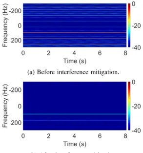
Fig. 4: Spectrograms of the received signal (a) before and (b) after interference mitigation. The figures are normalized with the respect to the maximum values obtained by (a).
The spectrograms shown in Fig. 4 are obtained by fol-lowing these process: the range bins are summed and then a Short Time Fourier Transform (STFT) is applied in slow time. The range bins are obtained by filtering the interference signal, (4), with a filter matched to the radar signal XαM(t). The spectrograms are generated by using
a Hamming window of length 0.742 seconds and 99 %
overlap.
Fig. 4a shows the spectrogram obtained applying the STFT on the received signal, where a strong frequency com-ponent is present due to the interfering signal, while Fig. 4b shows the spectrogram obtained when the interference is alleviated. Comparing these two figures we can see that the maximum intensity value at the Doppler frequency of the interference signal has been decreased by 22.6 dB.
In Fig. 3 it was shown that after the interference mitiga-tion the mean power has significantly reduced. In multi user scenarios, interference mitigation leads to an improvement in terms of estimation radar parameters. At the same time, in Fig. 4 it was demonstrated that the same processing can be applied to obtain an improvement on time frequency analysis.
VI. SDR RADAR ANDINTERFERENCEIMPLEMENTATION The proposed interference mitigation framework was im-plemented by means of a Software Defined Radio (SDR) device, namely the National Instruments Universal Software Radio Peripheral (NI-USRP) 2943R is used to transmit and receive the signals [16]. It is used with three wideband antennas, two for the mono-static radar configuration and one for the interference transmitter. The USRP 2943R is operated through GNU Radio. It is used to send and receive the signal to and from the USRP. The architecture design
Fig. 5: Architecture design.
is shown in Fig. 5. Initially the waveforms are generated in MATLAB. After this stage, the GNU Radio is used to read the file from MATLAB and forwards the signal to the USRP. In this architecture, the radar signal and interference signal are transmitted using two channels. The radar signal is transmitted through channel one, while the interference signal though channel two. When the antenna receives the signals, the GNU Radio reads the signal from the USRP and saves the samples in a file. At the end of these stages, the processing is done in MATLAB.
VII. INTERFERENCEMITIGATION ONREALSIGNALS The performance of the interference mitigation algorithm was evaluated on real data. The data were acquired in a controlled laboratory environment. The acquisition geometry is shown in Fig. 6. The mono-static radar is placed at bottom left, the interference user at the top right and the blue area indicates where a person is walking towards and away from the radar to generate a Doppler signal. The distance d is 180 cm. The data was acquired following two scenarios: one where the transmitter of the radar is switched off and one that is on. In the scenario where the transmitter is off, the target is not present and the PSD and the spectrogram are considered. On the other hand, when the transmitter is on a person walks front to the radar as shown in Fig. 6. In this experiment the same parameters presented in Section V are used. The received signal interference is
y(t) =R(t) +n(t) (8) whereR(t)is obtained by (5) whilenis the noise, where the mean value is -40 dB. The power of the received signal is estimated as described in Section IV, the difference between the received and estimated power is 0.13 dB, the estimation frequency is 100.12 Hz and the interference delay estimation is perfect.
The PSD obtained from the received signal (8) and that obtained after interference mitigation are shown in Fig.7. The maximum and mean values of the PSD obtained before
Fig. 6: Acqusition geometry of the laboratory-based exper-imental campaign.
Fig. 7: Power Spectral Density obtained on the real data before and after interference mitigation.
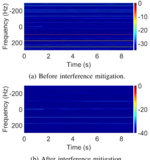
interference mitigation are 78.89 dB and 49.89 dB re-spectively, while after interference mitigation the maximum values is decreased by 7 dB the mean by 8 dB. The spectrograms shown in Fig. 8 are obtained when the target is not present. Comparing Fig. 8a with Fig. 8b we can see that the intensity at 100 Hz is decreased by 20.9 dB.
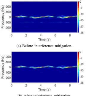
Finally, another analysis was performed in a scenario shown in Fig. 6, where the transmitter radar is on and a person is walking towards the radar. In Fig. 9a the Doppler due to the interference user (see 100 Hz) and micro-Doppler signature are present. In Fig. 9b, after the interference mitigation the micro-Doppler signature of the target remains unchanged while the contribution from the interference user has been decreased by 4 dB.
Comparing the results from the laboratory data with those from the simulated signal (see Section VII and Section V), it can be seen that lower interference reduction is achieved. Particularly, comparing the PSD in Fig.3 and Fig. 7 it is noted that for the simulation signal the mean and maximum of the interference is reduced by 16 and 18 dB while for the real signal a reduction of 7 and 8 dB is obtained respectively. Furthermore, comparing the spectrograms in Fig. 4 and Fig. 8 the maximum reduction of the interference
(a) Before interference mitigation.
(b) After interference mitigation.
Fig. 8: Spectrograms of the received signal (a) before and (b) after interference mitigation. The figures are normalized with the respect to the maximum values obtained by (a).
(a) Before interference mitigation.
(b) After interference mitigation.
Fig. 9: Spectrograms of the received signals (a) before and (b) after interference mitigation.The figures are normalized with the respect to the maximum values obtained by (a). in the simulated signal is 22.6 dB, while for the real signal the same value is 20.9 dB. In order to justify this drop in performance, the spectrum of the received and simulated signal are examined in Fig. 10. Comparing the two plots, Fig. 10, we can see that the spectra of the two signals are not the same. This is caused due to hardware impurities and not linearities. This mismatch between the real and recon-structed interference signal can play a significant part on the performance drop of the interference mitigation process. A possible solution would be to account for the system’s transmitter and receiver characteristics by calibrating the signal generator process with the individual system.
VIII. CONCLUSION
This paper presented a novel FrFT based interference mit-igation method for automotive environment. The proposed framework is successfully validated using an SDR device, and its performance is evaluated in the absence and presence of a human target. In the first cases, the performance is evaluated by considering a simulated and a real signal, where the real signal is acquired in a controlled laboratory environment. In both cases, the error on the frequency estimation is 0.12 Hz, the separation between two orders
Fig. 10: Spectrum of the received and simulated signal.
of the FrFT is 0.1, and has been shown that the interference is decreased. Finally, the framework is analysed when the target and interference are present. In this scenario it has been shown that the interference is decreased while the micro-Doppler signature does not change. The proposed interference mitigation algorithm can fail in cases where the interference will saturate the receiver. Additionally, the proposed framework takes into account only the amplitude of the radar processed signal this meaning that only pro-cessing that does not consider the phase can be applied such as CFAR and Neural Network (NN). Future developments include evaluating the performance in multi user scenarios.
ACKNOWLEDGMENT
This work is supported by NXP Laboratories UK Limited. REFERENCES
[1] D. Gaglione, C. Clemente, C. V. Ilioudis, A. R. Persico, I. Proudler, and J. J. Soraghan, “Waveform design for communicating radar systems using fractional fourier transform,”Digital Signal Processing, vol. 80, pp. 57–69, Sep 2018.
[2] F. Gini, A. D. Maio, and L. Patton,Waveform Design and Diversity for Advanced Radar Systems. The Institution of Engineering and Technology, 2012.
[3] P. Striano, C. V. Ilioudis, C. Clemente, and J. J. Soraghan, “Com-municating radar using frequency-shift keying and fractional fourier transform for automotive applications,”The Journal of Engineering, vol. 2019, no. 19, pp. 6016–6020, 2019.
[4] P. Striano, C. V. Ilioudis, C. Clemente, and J. J. Soraghan, “Per-formance of a communicating radar using fsk and fractional fourier transform for automotive applications,” in 2019 IEEE Radio and Wireless Symposium (RWS), pp. 1–4, Jan 2019.
[5] P. Striano, C. V. Ilioudis, C. Clemente, and J. J. Soraghan, “Frac-tional fourier transform based joint radar communication system for multi-user automotive applications,” in2019 IEEE Radar Conference (RadarConf), pp. 1–6, April 2019.
[6] M. Goppelt, H. . Bl¨ocher, and W. Menzel, “Analytical investigation of mutual interference between automotive fmcw radar sensors,” in 2011 German Microwave Conference, pp. 1–4, March 2011. [7] M. Kunert, “The eu project mosarim: A general overview of project
objectives and conducted work,” in2012 9th European Radar Con-ference, pp. 1–5, Oct 2012.
[8] J. Bechter, C. Sippel, and C. Waldschmidt, “Bats-inspired frequency hopping for mitigation of interference between automotive radars,” in 2016 IEEE MTT-S International Conference on Microwaves for Intelligent Mobility (ICMIM), pp. 1–4, May 2016.
[9] J. Bechter, F. Roos, M. Rahman, and C. Waldschmidt, “Automotive radar interference mitigation using a sparse sampling approach,” in 2017 European Radar Conference (EURAD), pp. 90–93, Oct 2017. [10] F. Uysal and S. Sanka, “Mitigation of automotive radar interference,”
in 2018 IEEE Radar Conference (RadarConf18), pp. 0405–0410, April 2018.
[11] Y. L. Sit, B. Nuss, and T. Zwick, “On mutual interference cancellation in a mimo ofdm multiuser radar-communication network,” IEEE Transactions on Vehicular Technology, vol. 67, pp. 3339–3348, April 2018.
[12] V. Namias, “The fractional order transform and its application to quantum mechanics,”IMA Journal of Applied Mathematics, vol. 65, no. 3, pp. 241–265, 1980.
[13] L. B. Almeida, “The fractional fourier transform and time-frequency representations,” IEEE Transactions on Signal Processing, vol. 42, pp. 3084–3091, Nov 1994.
[14] D. Manolakis and V. Ingle,Applied Digital Signal Processing: Theory and Practice. Cambridge University Press, 2011.
[15] H. Zhou, X. Li, M. Tang, Q. Wu, X. Chen, M. Luo, S. Fu, and D. Liu, “Joint timing/frequency offset estimation and correlation based on frft encoded training symbols for pdm co-ofdm systems,”Optical Express, vol. 24, Dec 2016.
[16] “Specification usrp-2943 software defined radio reconfigurable de-vice,”