University of Denver University of Denver
Digital Commons @ DU
Digital Commons @ DU
Electronic Theses and Dissertations Graduate Studies 1-1-2016
System Frequency Support of Permanent Magnet Synchronous
System Frequency Support of Permanent Magnet Synchronous
Generator-Based Wind Power Plant
Generator-Based Wind Power Plant
Ziping Wu
University of Denver
Follow this and additional works at: https://digitalcommons.du.edu/etd Part of the Power and Energy Commons
Recommended Citation Recommended Citation
Wu, Ziping, "System Frequency Support of Permanent Magnet Synchronous Generator-Based Wind Power Plant" (2016). Electronic Theses and Dissertations. 1091.
SYSTEM FREQUENCY SUPPORT OF PERMANENT MAGNET
SYNCHRONOUS GENERATOR-BASED WIND POWER PLANT
A DISSERTATION PRESENTED TO
THE FACULTY OF THE DANIEL FELIX RITCHIE SCHOOL OF ENGINEERING AND COMPUTER SCIENCE
UNIVERSITY OF DENVER
__________
IN PARTIAL FULFILLMENT
OF THE REQUIREMENTS FOR THE DEGREE DOCTOR OF PHILOSOPHY
__________ by ZIPING WU MARCH 2016
©Copyright by Ziping Wu 2016 All Rights Reserved
Author: Ziping Wu
Title: System Frequency Support of Permanent Magnet Synchronous Generator-based Wind Power Plant
Advisor: David Wenzhong Gao Degree Date: March 2016
Abstract
With ever-increasing penetration of wind power into modern electric grids all over the world, a trending replacement of conventional synchronous generators by large wind power plants will likely result in the poor overall frequency regulation performance. On the other hand, permanent magnet synchronous generator wind Turbine System (PMSG-WTG) with full power back to back converters tends to become one of the most promising wind turbine technologies thanks to various advantages. It possesses a significant amount of kinetic energy stored in the rotating mass of turbine blades, which can be utilized to enhance the total inertia of power system. Additionally, the deloaded operation and decoupled control of active and reactive power make it possible for PMSG-WTG to provide a fast frequency regulation through full-power converter.
First of all, a comprehensive and in-depth survey is conducted to analyze the motivations for incorporating the inertial response and frequency regulation of VSWT into the system frequency regulation. Besides, control classifications, fundamental control concepts and advanced control schemes implemented for auxiliary frequency support of individual WT or wind power plant are elaborated along with a comparison of the potential frequency regulation capabilities of four major types of WTs.
Secondly, a Controls Advanced Research Turbine2-Permanent Magnet Synchronous Generator wind turbine (CART2-PMSG) integrated model representing the
typical configuration and operation characteristics of PMSG-WT is established in Matlab/Simulink,. Meanwhile, two different rotor-side converter control schemes, including rotor speed-based control and active power-based control, are integrated into this CART2-PMSG integrated model to perform Maximum Power Point Tracking (MPPT) operation over a wide range of wind speeds, respectively.
Thirdly, a novel comprehensive frequency regulation (CFR) control scheme is developed and implemented into the CART2-PMSG model based on rotor speed control. The proposed control scheme is achieved through the coordinated control between rotor speed and modified pitch angle in accordance with different specified wind speed modes. Fourth, an improved inertial control method based on the maximum power point tracking operation curve is introduced to boost the overall frequency support capability of PMSG-WTGs based on rotor speed control. Fifth, a novel control method based on the torque limit (TLC) is proposed for the purpose of maximizing the wind turbine (WT)'s inertial response. To avoid the SFD caused by the deloaded operation of WT, a small-scale battery energy storage system (BESS) model is established and implemented to eliminate this impact and meanwhile assist the restoration of wind turbine to MPPT mode by means of coordinated control strategy between BESS and PMSG-WTG.
Last but not the least, all three types of control strategies are implemented in the CART2-PMSG integrated model based on rotor speed control or active power control respectively to evaluate their impacts on the wind turbine’s structural loads during the frequency regulation process. Simulation results demonstrate that all the proposed methods can enhance the overall frequency regulation performance while imposing very
Acknowledgements
First of all, I would like to express my sincere appreciations to my academic supervisor, Dr. David Wenzhong Gao, for his guidance, inspiration and support during my Ph.D study at the University of Denver (DU). I am deeply grateful to him for his wisdom and expertise that assist me in accomplishing this dissertation.
Secondly, I would like to heartily extend my sincere gratitude to Dr. Eduard Muljadi, a principle engineer in NREL and an extinguished IEEE fellow, for his careful guidance and wonderful suggestions that takes my research to a higher level.
Thirdly, I am very grateful to Dr. Mohammad Matin, Dr. Jun Zhang and Dr. Duan Zhang for their valuable time to serve as my committee members as well as for their consistent support and advice about my research.
Next, I would like to thank Dr. Kimon Valavanis, the chair of Department of Electrical and Computer engineering for his durable support and assistance. Many special thanks go to other faculties and staffs in the Daniel Felix Ritchie School of engineering and computer science for their kind assistance and care during my study at DU. I also would like to thank all my great lab fellows at the Renewable Energy and Power Electronics Laboratory at DU for their support and valuable ideas they share with me.
Last but not the least, I am especially grateful to my great parents who provide me continued support and unconditioned assistance during my hardest time. Their love, trust and understanding enable me to accomplish my Ph.D study smoothly.
Table of Contents
Abstract ... II Acknowledgements ... IV Table of Contents ... V List of Figures ... VII List of Tables ... X
Chapter 1 Introduction... 1
1.1Background and Motivation ... 1
1.2Research Objectives ... 4
1.3 Contributions... 5
1.4Outline of Dissertation ... 7
Chapter 2 Literature Review on the Frequency Response by Wind Power Plants in the Power Grid ... 9
2.1 Wind Turbine Ancillary Functions ... 9
2.1.1 Inertial Control ... 10
2.1.2 Primary Frequency Control ... 21
2.1.3 Secondary Frequency Control /AGC ... 31
2.1.4 Tertiary Frequency Control ... 32
2.1.5 Coordinated Frequency Control ... 33
2.2Performance of Various Speed Wind Turbine Generations on Frequency Regulation ... 36
2.2.1 Type 1 and Types 2 FSWTs ... 37
2.2.2 Type 3 and Type 4 VSWTs ... 38
2.3 Conclusion and Discussion... 40
Chapter 3 Modeling and Simulation of a CART2-PMSG Integrated Model ... 41
3.1 CART2 Test Bed... 42
3.2CART2 Simulink Model ... 43
3.3CART2-PMSG Integrated Model ... 45
3.3.1 Modeling of Pitch control model ... 48
3.3.2 Modeling of Permanent Magnet Synchronous Generator ... 49
3.3.3 Modeling of Power Converter System ... 50
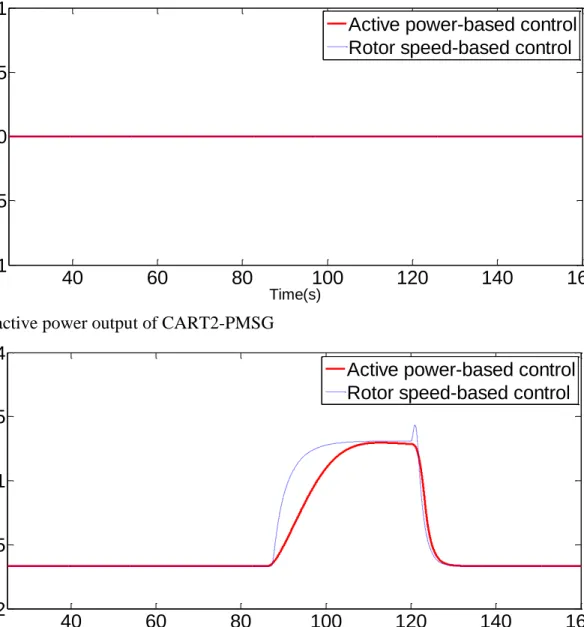
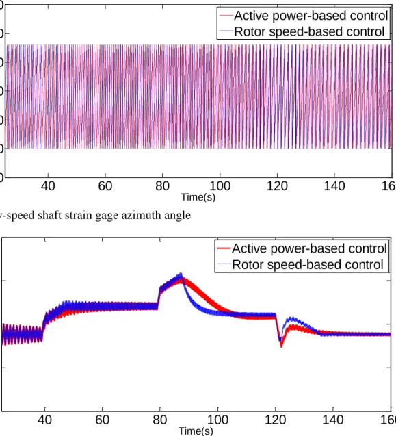
3.4Simulation Results and Discussion ... 53
3.5 Conclusion ... 69
Chapter 4 A Comprehensive Frequency Regulation Scheme for PMSG-WTG with pre-deloaded operation ... 70
4.1 Coordinated Frequency Controller Design for PMSG-WTG System ... 71
4.1.1 Rotor Speed Control ... 74
4.1.2 Modified Pitch Angle Control ... 80
4.2Comprehensive Frequency Control Scheme ... 81
4.4.1 Simulation Results for Electrical System ... 87
4.4.2 Simulation Results for FAST Mechanical Stresses ... 93
4.4 Comparison and Discussion ... 101
4.5 Conclusion ... 106
Chapter 5 Frequency Support of PMSG-WTG Based on Improved Inertial Control without Pre-deloaded Operation ... 108
5.1 Improved Inertial Control Method of PMSG-WTG ... 108
5.2 Model System and Case Study ... 113
5.3 Simulation Results ... 115
5.4 Comparison and Discussion ... 120
5.3 Conclusion ... 123
Chapter 6 Coordinated Control Strategy of BESS and PMSG-WTG to Enhance the Frequency Regulation Capability ... 125
6.1Torque Limit Control for Enhanced Inertial Response ... 126
6.2Dynamic Modeling of BESS ... 129
6.2.1 Modelling of Battery Module ... 129
6.2.2 Modeling and Control of BESS Inverter ... 133
6.2.3 Frequency Support Control of BESS for Inertial Recovery of PMSG-WTG ... 138
6.3 Coordinated Control Strategy of BESS and PMSG-WTG ... 141
6.4 Test System with Integration of CART2-PMSG and BESS ... 144
6.5 Simulation Results ... 147
6.6 Comparison and Discussion ... 154
6.6 Conclusion ... 156
Chapter 7 Conclusion and Future Work ... 158
7.1 Conclusion ... 158
7.2 Future Work ... 160
List of Figures
Figure 1.1 Schematic of research project plan ... 4
Figure 2.1 Schematic diagram of comprehensive frequency control following a large generation loss or a sudden load change ... 10
Figure 2.2 Control strategy of one shot controller ... 15
Figure 2.3 Control block diagram of the continuously acting controller ... 16
Figure 2.4 Control block diagram of the constant inertial response based on rotor speed regulation . 18 Figure 2.5 Control block diagram of the constant inertial response based on active power control ... 19
Figure 2.6 Control block diagram of VIC ... 20
Figure 2.7 Control block diagram of droop response ... 22
Figure 2.8 Frequency-power characteristics of basic droop control ... 23
Figure 2.9 Schematic diagram of modified pitch angle control strategy ... 29
Figure 2.10 90% PMSG-WT sub-optimal operation curve ... 31
Figure 2.11 Schematic diagram of load-frequency control loop ... 33
Figure 2.12 Coordinated frequency control strategy for VSWT ... 35
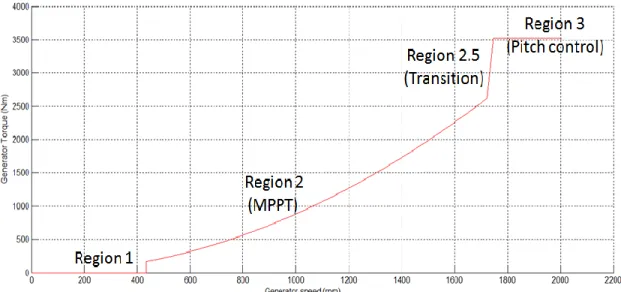
Figure 3.1 Variable-speed turbine operating regions of the CART2 model ... 43
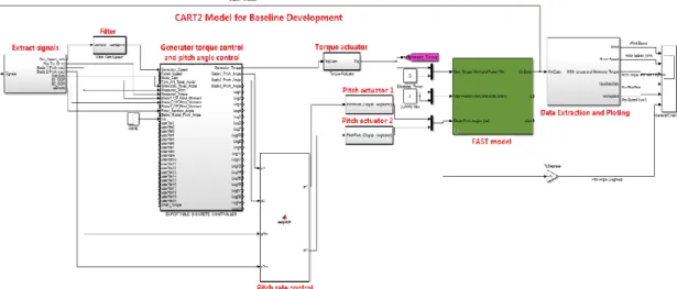
Figure 3.2 The configuration of CART2 simulink model ... 44
Figure 3.3 Simple flowchart of the CART2 baseline Simulink model ... 45
Figure 3.4 Fundamental control structure of the CART2-PMSG integrated model ... 46
Figure 3.5 CART2-PMSG integrated model in Matlab/Simulink ... 46
Figure 3.6 Schematic of pitch angle control ... 48
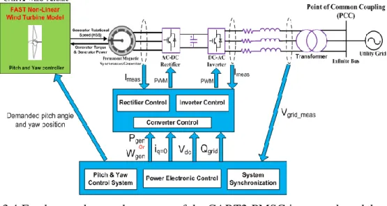
Figure 3.7 The basic control scheme of proposed PMSG-WTG system connected to an infinite bus. 52 Figure 3.8 Simulation results for the PMSG model under step-wise wind speed conditions ... 55
Figure 3.9 Simulation results for FAST-based CART2 model under step-wise wind speed conditions ... 60
Figure 3.10 Simulation results for the PMSG model under realistic wind speed conditions ... 63
Figure 3.11 Simulation results for FAST-based CART2 model under realistic wind speed conditions 68 Figure 4.1 Overall control configuration of a typical PMSG-WTG system equipped with the CFR scheme ... 73
Figure 4.2 Control block diagram of constant inertia response ... 76
Figure 4.3 80% de-loaded operation curve with the rotor speed limitation (0.5 p.u.-1.0 p.u.) over a full scope of wind speeds ... 77
Figure 4.4 Control block diagram of droop response ... 78
Figure 4.5 The variable slope droop curve versus the reserve power ... 79
Figure 4.6 Schematic of modified pitch angle controller ... 81
Figure 4.7 Schematic of comprehensive frequency regulation controller at the rotor-side converter . 82 Figure 4.8 Basic configuration of a small test system ... 87
Figure 4.9 Simulation results of electrical system under the low wind speed. ... 89
Figure 4.10 Simulation results of electrical system under the medium wind speed. ... 91
Figure 4.11 Simulation results of electrical system under the high wind speed... 93
Figure 4.12 Simulation results of mechanical stresses under the low wind speed. ... 95
Figure 4.13 Simulation results of mechanical stresses under the medium wind speed. ... 98
Figure 4.14 Simulation results of mechanical stresses under the high wind speed. ... 100
Figure 5.1 Power‒rotor speed trajectory ... 111
Figure 5.2 Complete set of the improved inertial control scheme ...112
Figure 5.3 Basic configuration of a small-scale power grid system ...114
Figure 5.4 Simulation results for the grid side ...116
Figure 5.5 Simulation results for the electrical system of CART2-PMSG ...118
Figure 5.6 Simulation results for the mechanical stresses of CART2-PMSG ... 120
Figure 6.1 Power‒rotor speed trajectory for TLC ... 128
Figure 6.2 Control block of the complete TLC inertial response scheme ... 129
Figure 6.3 Equivalent circuit of the generic battery ... 131
Figure 6.4 Typical discharge characteristics of generic battery ... 132
Figure 6.5 Nominal current discharge characteristic for specified lead-acid battery ... 132
Figure 6.6 Inverter structure of BESS in the charging mode ... 133
Figure 6.7 Control structure of BESS's inverter ... 138
Figure 6.8 Control block of BESS participating in the coordinated frequency control ... 139
Figure 6.9 Flow chart of coordinated control scheme for PMSG-WTG, BESS and other conventional generators ... 144
Figure 6.10 Basic configuration of a small-scale power grid system ... 146
Figure 6.11 Simulation results of electrical system of CART2-PMSG ... 148
Figure 6.12 Simulation results of mechanical stresses of CART2-PMSG ... 151
List of Tables
Table 3.1 List of CART2 modified parameter values ... 47
Table 4.1 Result comparisons among various frequency regulation methods in case 1 ... 103
Table 4.2 Result comparisons among various frequency regulation methods in case 2 ... 103
Table 4.3 Result comparisons among various frequency regulation methods in case 3 ... 104
Table 5.1 Comparison of system frequency characteristics ... 121
Table 6.1 The parameters of lead-acid battery ... 130
Chapter 1 Introduction
1.1 Background and Motivation
Nowadays, a growing penetration of variable-speed wind turbine generators (VSWTGs) based on permanent magnet synchronous generators (PMSGs) and doubly-fed induction generators (DFIGs) may result in a decline in the system frequency regulation capability. That's due to VSWTG's decoupling interface between rotor speed and grid frequency via power converter as well as the declined inertia from conventional synchronous generators being gradually replaced or de-committed [1].
However, PMSGs inherently possesses a significant amount of kinetic energy stored in the rotating mass of their turbine blades and gearbox, and this can be employed to strengthen total inertia of a power system through fast and flexible power converter control. Moreover, fully decoupling the rotor speed from the grid frequency allows PMSGs to remain in stable operation and rapidly respond to grid frequency variations in any severe frequency event. Compared to DFIGs featured with identical power rating and inertial constant, PMSGs are capable of providing the larger inertial response and stronger frequency support thanks to their full power converter, which accommodates a wider range of rotor speed (0.4 p.u-1.2 p.u) in comparison with that of DFIG-WTG (0.7p.u. to 1.2p.u.) [2]-[3]. Therefore, it is valuable for the grid to take full advantage of the potential capability of PMSG-WTGs in supporting system frequency regulation.
From the perspective of secure power grid operation, Regional Transmission Organizations (RTOs) and Independent System Operator (ISOs) in many countries have come to realize the potential benefits of inertial response and frequency regulation provided by wind turbine (WT) in maintaining the dynamic active power balance between generation and demand. From the perspective of wind turbine manufacturers, the integration of auxiliary frequency control functions, consisting of de-loaded control, inertial response and primary droop control and automatic generation control (AGC) secondary control, can be simply realized by altering the existing control strategy of power converter and pitch angle control [4]-[5]. Besides, a large number of wind generators with frequency regulation functions are allowed to be integrated into power system, which yields extra profits by providing the ancillary service. With a great potential demand in power market, wind plant manufactures are also encouraged to further improve the VSWT's auxiliary frequency control customized for specific power system. On the other hand, especially when the wind power needs to be dispatched down in case of low load demand and high wind speed condition or according to other operation constrains, a certain amount of untapped wind power can be harnessed as spinning reserve to assist in the system frequency regulation under the subsequent severe disturbances [4]. Therefore, a win-win solution can be achieved by implementing the frequency control into PMSG-WTG for the mutual benefits of wind power plants and electrical power grid.
In most current literatures, auxiliary frequency controllers are proposed as add-on functions for DFIG-WTG. Therein, the inertial control utilizes the kinetic energy in the rotating mass of wind turbine (WT) to provide the temporary frequency response [6]-[8].
The de-loaded control enables the wind turbine to run in the de-loaded mode so as to reserve partial wind power for the primary and secondary frequency regulations [9]-[13]. The droop control emulates the primary frequency response of conventional synchronous generators [6],[10],[14]-[15]. A secondary frequency controller in a supervisory wind farm control system can respond to an AGC signal or the power flow adjustment from the transmission system operator [11]-[13]. As for the comprehensive control based on the above controllers, a coordinated frequency regulation scheme is presented for DFIG-WTG operating under different wind speeds in [16]. The frequency response capability of the full converter variable speed wind turbine generator in the Maximum Point Power Tracking (MPPT) mode is investigated under different constant wind speed conditions in [15]. Overall, the vast majority of current researches are centered on the DFIG-WTG frequency regulation capabilities due to its current higher market share [2],[6],[9],[11]-[14],[16]. Very a few published papers or documents emphasize the comprehensive frequency regulation capacity of PMSG based on rotor speed-based control under different wind speeds or enhanced inertial response based on active power-based control when operating in MPPT mode, especially with respect to the potential impact of frequency regulation on the mechanical components of wind turbines.
Therefore, the research presented herein intends to address the major issues as to maximize the performance of PMSG-WTG for short-term and long-term frequency regulations in accordance with its specific operation characteristics and control structure. Meanwhile, the impact of frequency support on the WT's mechanical stress and structural load should be carefully observed when enabling PMSG-WTG to perform the proposed
1.2 Research Objectives
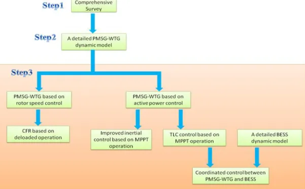
The objective of this research is to provide fundamental knowledge about the frequency regulation by VSWTGs and advanced controller design that enables PMSG-WTGs based on rotor speed control or active power control to provide the optimal frequency support. This dissertation work is mainly focused on the development and implementation of the enhanced inertial response and primary frequency regulation, which is suitable for PMSG-WTGs in terms of de-loaded operation and MPPT mode respectively. Specific objectives and procedures of research project are illustrated in Figure 1.1:
Figure 1.1 Schematic of research project plan
The first objective of this project is to conduct a comprehensive and in-depth survey on the inertial response and auxiliary frequency regulation provided by various types of wind generations.
The second objective of this project is to design and develop a detailed PMSG-WTG model with aerodynamic and mechanical components represented by the FAST-based CART2 model. The purpose of this work aims to construct a reliable simulation platform that is able to accurately represent the physical characteristics and dynamic performance of real PMSG-WTG over different wind speeds, so that the development and validation of the proposed frequency control schemes can be carried out by investigating their impacts on the power grid and wind turbine simultaneously.
The third objective of this project is to develop a novel comprehensive frequency regulation (CFR) scheme for PMSG-WTGs based on rotor speed control by combining rotor speed control with modified pitch angle control. The implementation of this control strategy is based on the de-loaded operation of PMSG-WTG over a wide range of wind speeds.
The fourth objective of this project is to develop an improved inertial control to enable the PMSG-WTG based on rotor-speed control to improve the overall frequency support in case of large supply-demand imbalances. The implementation of this control strategy is based on MPPT operation without additional power reserve required. If necessary, Battery Energy Storage System (BESS) can be employed to coordinated with the PMSG-WTG to accomplish the temporary frequency support.
1.3 Contributions
The main contributions of this project are listed as follows:
1) To come up with a novel comprehensive frequency control (CFR) scheme, which is suitable for PMSG based on rotor-speed control to achieve both constant
inertial response and variable droop frequency regulation by coordinating the rotor speed control and pitch angle control. Moreover, a complete operation of PMSG is categorized into the low, medium and high wind speed modes according to the deloaded margin level and rotor speed limit. By implementing the proposed CFR scheme, the rotor-speed-control oriented PMSG-WTG is enabled to optimally participate in the short-term and long-term frequency regulation over a full range of wind speeds.
2) To present an improved inertial control method based on the maximum power point tracking operation curve to enhance the overall frequency support capability of power control-based PMSG-WTGs when they are operating in MPPT mode. In the meanwhile, the possible secondary frequency drop (SFD) can be mitigated in case of severe frequency disturbance.
3) To make the same PMSG-WTG perform much stronger inertial response, a follow-up control method based on the torque limit (TLC) is proposed to signifcantly enhance the temporary frequency support within the mechanical constraint. To avoid its subsequent Secondary SFD issue resulting from WT's inertial energy recovery, a small-scale BESS is employed to eliminate this impact and meanwhile assist the wind turbine in restoring the rotor speed to MPPT mode through the proposed coordinated control strategy of BESS and PMSG-WTG. 4) Last but not the least, all three types of control strategies are implemented in the
CART2-PMSG integrated model based on rotor speed control or active power control to study their impacts on the wind turbine’s structural loads during the inertial response process.
1.4 Outline of Dissertation
The remaining parts of this dissertation presents a detailed study of three control methods discussed previously, in addition to a comprehensive survey of frequency regulation by wind farm plants.
Chapter 2 presents a complete literature review on the frequency response by wind power plants. It specifically describes the control concepts, theories and principles of prevailing frequency regulation apart from the frequency regulation performance comparison among four major types of WTG. Furthermore, this review also provide a overview of the latest industry development and applications, ongoing domestic and international research activities as well as updated grid codes associated with the VSWT's emerging frequency regulation technologies. Finally, authors provide a comprehensive insights and analysis into several critical issues with respect to the participation of VSWTs in the grid frequency regulation from perspectives of system operation, control, protection as well as power market.
Chapter 3 presents a detailed CART2-PMSG wind turbine model equipped with two different control strategies, consisting of rotor speed-based control and active power-based control. Based on a series of simulation tests, it is proved the proposed CART2-PMSG integral model can accurately represent the steady-state and dynamic characteristics of real wind turbine in terms of both mechanical and electrical aspects when both control strategies are implemented in the rotor-side converter, respectively.
Chapter 4 presents a novel comprehensive frequency regulation (CFR) scheme fit for PMSG-WTGs based on rotor speed control by combining rotor speed control with
modified pitch angle control. It is concluded that the CFR can enable PMSG-WTG to contribute to the active power regulation and promote the overall frequency regulation performance in case of frequency disturbance.
Chapter 5 presents an improved inertial control method based on the maximum power point tracking operation curve to enhance the overall frequency support capability of PMSG-WTGs in the case of large supply-demand imbalances. Simulation results demonstrate that the improved inertial control enables the PMSG-WTG to enhance the transient frequency regulation performance even in the low wind power penetration condition, whereas the proper deloaded value can avoid the SFD throughout the rotor speed recovery process.
Chapter 6 presents a coordinated control strategy of BESS and PMSG-WTG to improve the overall frequency characteristics. A novel control method based on the torque limit (TLC) is proposed to maximize the PMSG-WTG's inertial response. To avoid the undesirable secondary frequency drop (SFD), a small-scale BESS model is utilized to support the wind turbine to recover to the MPPT state by using the proposed coordinated control scheme.
Chapter 7 provides a conclusion of the presented research work and several recommendations for the future work.
Chapter 2 Literature Review on the Frequency Response by Wind
Power Plants in the Power Grid
This work conducts a comprehensive survey on the inertial response and auxiliary frequency regulation provided by various types of wind generations. It specifically describes, analyzes and illustrates the prevailing frequency regulation controls of VSWT from the perspectives of fundamental frequency regulation concepts, control principles and coordinated control strategies. Besides, a concrete comparison on the potential performance of four popular types of wind power plants is illustrated with respect to system frequency regulation capability including their benefits and drawbacks.
2.1 Wind Turbine Ancillary Functions
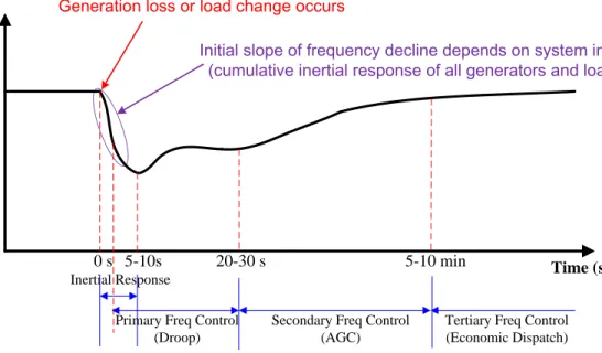
In principle, grid frequency response can be divided into four regulation stages in the time scales: inertial response, primary frequency response, secondary frequency response and tertiary frequency response as shown in Figure 2.1 [17]. Until now, active power control strategies applied in the rotor side converter of VSWT involve torque control, active power control and rotor speed control in order to realize the MPPT operation mode [18],[20]-[24]. To equip VSWT with emulated frequency regulation functions, supplementary frequency controllers should be carefully designed and integrated into both converter power control loop and pitch angle control loop to
manipulate the corresponding set points like torque, active power or rotor speed according to specific frequency regulation requirement[10], [19] ,[25]-[29].
0 s 20-30 s 5-10 min
Secondary Freq Control (AGC) Primary Freq Control
(Droop)
Tertiary Freq Control (Economic Dispatch) Inertial Response 5-10s Time (sec) G ri d F re q u en cy ( H z)
Initial slope of frequency decline depends on system inertia (cumulative inertial response of all generators and loads)
Generation loss or load change occurs
Figure 2.1 Schematic diagram of comprehensive frequency control following a large generation loss or a sudden load change (Figure derived from Pouyan Pourbeik of EPRI)
2.1.1 Inertial Control
In a power system, inertial response is an immediate response to severe frequency excursion within seconds due to the sudden and large power supply-demand imbalance. The system frequency changes at a certain rate initially determined by the cumulative inertia of all spinning generations (synchronous generators) and the composite load damping (motor, pumps and et al) [30]-[32]. The additional energy stored in rotating mass of both wind turbine and generator can be extracted and then released into the power grid via grid-side converter to arrest the rate of change of frequency (ROCOF). For instance, the typical value of wind turbine inertia is approximately 3.5s [33]. The total moment of inertia of a 2 MW-scale VSWT is approximately six times than that of the conventional generator [14].
Once the inertial energy is totally released up at the moment of frequency nadir, the energy extracted from the rotating mass needs to be recovered from the available wind power in order to restore the WT rotor speed and kinetic energy to their pre-disturbance value. In this sense, the inertial control is essentially “the energy neutral process” although the total amount of recovery energy can be greater than that of inertial response due to the WT mechanical and electrical losses during this process [34]. The duration of the natural recovery depends on the turbine mechanical dynamics and normally sustains several tens of seconds. A short-term dip may occur to the active power output during the recovery process for a portion of wind energy is utilized to restore the kinetic energy. Thus, a large aggregated energy recovery of wind farms will result in a secondary system frequency drop at some 10 to 15 seconds (even lower than the first frequency nadir) following the initial generation loss [14],[7]-[8],[35]-[44]. With respect to the inertial recovery process, three main parameters that determine its behavior include starting time to reduce active power, generation reduction amount as percentage of WT rated power (or actual power output level) as well as total duration for generation reduction [7]. The acceleration period of the WT rotor speed is set to be longer than the deceleration period by changing the rate of power ramp so as to relieve the pressure brought about by restoring process on the rest of the system [3]- [4].
According to the equation (1), the amount of kinetic energy ∆E for the inertial response of a single wind turbine is mainly determined by the initial rotor speed , rotor speed variation the moment of inertia of wind turbine
[Joule] (2.1)
Furthermore, the inertial response capability of a wind power plants is dependent on the wind power penetration level, the number of WTs capable of providing inertial response, initial operation mode of a single WT under full load or partial load as well as individual WT physical characteristics, including the upper and lower limits of rotor speed, over-loading capability of power converter and generator, auxiliary controller parameters, maximum rate of change of power
as well as reserve margin level
[39]-[40], [45]-[50]. To alleviate mechanical stresses on WT drive trains and extend its lifetime, the
should not exceed 0.45 p.u./s according to several manufacturers'
datasheets [45]. A certain reserve margin can supply power headroom for VSWT to perform enhanced inertial response, and also eliminate or reduce the impact resulting from inertial response recovery [7][50]. Under low wind speed condition where WTG operates just above the minimum rotor speed, kinetic energy available for inertial response is quite limited due to stalling prevention and a relatively long response restoration follows. In between medium and high wind conditions where WTG operates at MPPT conditions, adequate kinetic energy is available to provide inertial response, so as to shorten the recovery period and mitigate the decline in rotor speed. Under high wind speed condition that rotor speed is maintained at the rated value due to pitch angle control, kinetic energy cannot be released until rotor speed drops below the rated. The inertia response is finite since the total power output of a single WT cannot exceed the specified overloaded value (eg.1.1p.u.) due to the capacity limits of power converter [34].
Inertial response dominates initial frequency variation following a frequency disturbance, so it plays an essential role in determining the sensitivity of system frequency to power imbalance. In the meantime, emulated inertia control can obviously improve the system small signal stability since the system damping effect of the dominant oscillation mode can be further reinforced [51]. In general, the greater the rotor speed from WT declines, the higher the transient active power surge becomes following the disturbance and the more positive effect will result in the frequency excursion, despite more time is needed to arrive at another steady state condition [36]. With the WT's contribution to system inertia, ROCOF (rate of change of frequency) and frequency nadir (the lowest point of frequency) can be improved to eliminate the possibility of load shedding triggered by UFLS (under frequency load shedding) protection scheme, and thus improve the system reliability during large loss-of-supply events [52]. Meanwhile, another benefit of enhanced inertia response of VSWT is to decrease the times of peak power output from the conventional generators, which picks up the load at their slow rates after the frequency disturbance.
However, the industrial design of inertia response must respect the WTG's component constrains consisting of converter and generator electrical ratings as well as mechanical loadings, such as turbulence management, drive-train and tower loads. Until now, three typical sorts of inertial control have been proposed to equip VSWT with emulated inertial response, which can be mainly categorized into Natural Inertial Control, Constant Inertial Control and Virtual Inertia Control [6],[26],[14], [7],[35]-[42].
Natural inertial control is proposed to generate an WT incremental active power following a severe frequency decline, which magnitude is in proportion to ROCOF
to
emulate a synchronous inertia-alike response [43]. Currently, there are two main types of natural inertial controllers consisting of a one shot
controller and a continuously acting
controller [16],[44].
The one shot
controller is proposed to deliver an initial power surge in
proportion to the ROCOF once the frequency event occurs. A certain amount of kinetic energy featured with a defined ramp rate and decay period is immediately injected into grid from the inception of frequency drop. This control scheme can be implemented by applying a lookup table with the initial
value as X-coordinate and the corresponding
active power increment as Y-coordinate. As is shown in Figure 2.2, the full active power output can be achieved within 200ms and then declines exponentially over a specified duration of TS. A short power recovery period of 0.95 p.u. or above of nominal power is allowed but restricted to avoid the risk of subsequent frequency disturbance because other generation is offline or load unexpectedly rises [44].
df/dt (Hz/s)
Pref
(p.u of rated power)
200ms
0s Ts
Length of injection in consistent with the time taken to frequency minimum Permitted recovery period (TBD) for the kinetic energy following restoration of system frequency Active power decay which is proportional
to the rate of change of frequency (df/dt)
1.054 1.039 1.0137 1.0092 0.325 0.225 0.19 0.13 0.05 0.92% PNom 1.37% PNom 5.4% PNom Pincrease (MW)) 1.0 (Pnom) -0.95 t (s) Instant power injection determined by df/dt
3.9% PNom
Figure 2.2Control strategy of one shot
controller The continuously acting
controller is developed with a continuously acting
controller, which works through the entire disturbance to regulate the additional active power injection based on ROCOF . As to this control method, the per unit inertial power
and per unit inertial torque generated by inertial controller are expressed as
(2.2)
(2.3)
where, is the gain of the inertial controller, is the per-unit synchronous generator speed. is analogous to the equivalent moment of inertia.
corresponds to the part of the rotor kinetic energy extracted for the additional active power injection. Usually, the
can be superseded by
so that the WT inertial
response magnitude is directly proportional to the ROCOF. Using traditional method, is simplified as twice total inertia constant H of the wind turbine [35],[53].
However, to make PMSG-WT supply the appropriate inertial response, the value
stalling [16]. A low pass filter is added after derivative function block to minimize the interference from measurement noise. Moreover, the natural inertia control is also named as delta power control because of the shape of inertial power output resembling “delta” throughout the overall response process. Figure 2.3 presents the control block diagram of natural inertia response. The performance of WT's natural inertia response can be enhanced by either increasing the auxiliary controller gain K or relaxing the limit on the rate of change of electrical power output [45].
Last but not least, it is noted that the
is inherently a noise amplifying process,
which likely cause unpredictability of emulated inertial response. So, a proper filtering is required to eliminate this noise. However, the inertial controller relying on the
is
triggered equally by the pseudo generation tripping like switching incidents [46] .
d dt K sys f Low pass filter Converter Control Deadband * inertial P max P min P dP dt/ max (dP dt/ ) min ( / )dP dt
Figure 2.3 Control block diagram of the continuously acting
controller B. Constant inertial control
Constant inertial response is defined as a certain amount of constant active power, which is released from kinetic energy sustaining for up to ten seconds under various wind speed conditions [3],[42],[54][54]. Compared with natural inertial response, the inertial power using this control can be tuned in different shapes in accordance with its magnitude and duration and also its response is much faster without relying on the measurement of ROCOF. This control method can significantly uplift the frequency nadir and mitigate the impact of kinetic energy recovery by tuning a desirable and steady
additional power injected into the grid, being carried out without relying on the instantaneous system frequency [43]. The effect of constant inertia response is usually dependent on several factors including overproduction step amount, duration time, ramp rate limit for power descending and ascending stages, wind speed (namely, present wind power output) as well as the inertia constant HWT.
One control method is proposed to generate the constant inertial response by modifying the rotor speed set point throughout the frequency event. The constant inertial power is derived from
(2.4) where, t is the duration for constant inertial power, is the initial rotor speed
and is the rotor speed at the end of inertial response. Therefore, the reference value of rotor speed is available as:
(2.5)
By substituting inertial constant
into (2.5) and defining
as per-unit rotor speed plus
as per-unit inertial power, the per-unit rotor speed reference is rewritten in the per-unit form:
(2.6)
The control block diagram of constant inertial response is depicted in Figure 2.4.
Eq(2.6)
t
ref controllerPI , r meas Converter Control * inertial P max P min P dP dt/ max (dP dt/ ) min (dP dt/ ) _ . . ro p u _ max ref _ min ref _ . . in p u PFigure 2.4 Control block diagram of the constant inertial response based on rotor speed regulation
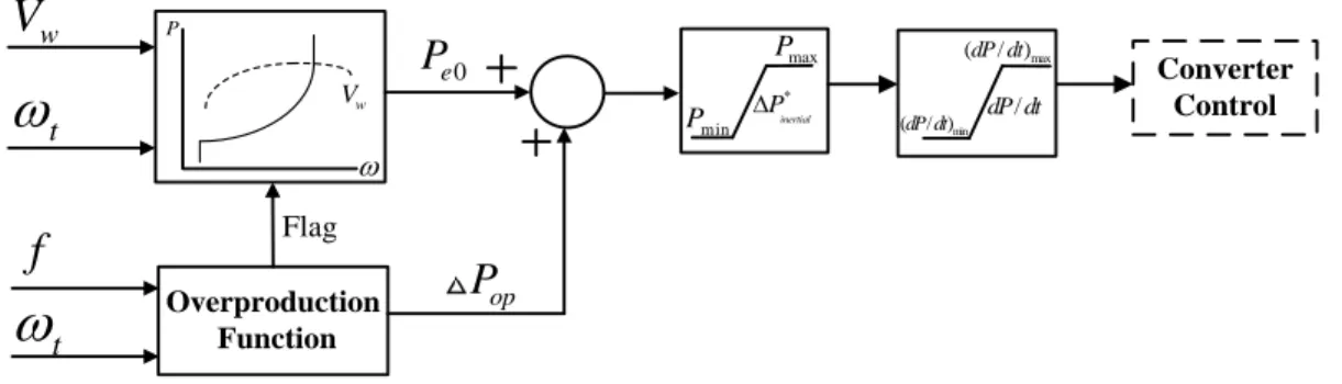
The other method to carry out the constant inertial control is proposed in [31] to increase the actual power reference by adding Temporary Over-Production (TOP) value ∆Pop on top of the pre-event active power reference Pe0 in case of frequency disturbance. The ∆Pop is derived from the kinetic energy stored in the WT rotating masses. Thus, the generated electrical power output Pe is defined as:
During the normal operation, VSWT runs on the MPPT point according to the actual wind speed. In the event of frequency, a constant over-production in a quantity ∆Pop is achieved by quickly altering the active power set point through power converter, so that the rotor speed maintains deceleration as a result of the increasing imbalance in mechanical and electromechanical torque. Until the rotor speed reaches , the
overproduction process will be over and then the active power set point will be adjusted to enable the electrical power output below the mechanical power input by a constant quantity Pacc. During this underproduction period, the rotor speed is accelerated and returned to previous MPPT point for the given wind speed or another operation point corresponding to the new wind speed. In Figure 2.5, the basic principle of this control mechanism is illustrated. Note that the value of Pacc can be constant or variable, depending on the specific strategy selected during the underproduction period. By
increasing the Pacc, the underproduction period is shorten and meanwhile the wind turbine rotor speed can be restored to the optimal operating point more rapidly. Assumed a bigger VSWT inertia constant, the overproduction and associated recovery periods are much longer due to larger kinetic energy stored.
w
V
t
Pe0 P w Vf
t
MPPT Function & Mechanical Power Estimator Overproduction Function Flag op
P
Converter Control * inertial P max P min P dP dt/ max (dP dt/ ) min (dP dt/ )Figure 2.5Control block diagram of the constant inertial response based on active power control
However, the extra active power production using this TOP method is always followed by an acceleration process, which more likely results in negative effect on the system frequency due to reduced power output of VSWT. Thus, an Improved Primary Frequency Response (IPFR) technique based on TOP method is proposed in [2] to avoid the acceleration phase and reduce the frequency deviation by combing de-loaded approach with TOP control. This IPFR response is mainly determined by over-production step magnitude, duration and wind speed condition. IPFR method can allow VSWT to enhance the overall system inertia response without under-production stage.
C. Virtual inertial control
Recently, another novel inertial control strategy named virtual inertia control (VIC) is presented to utilize the “hidden inertia” of the turbine blades to provide a fast dynamic frequency support. One method is to adjust the active power output of DFIG
response. This type of regulation can be implemented by means of shifting operating point from the MPPT power tracking cure toward the VIC power tracking curve to compensate for the mismatch in the power supply and demand and then rotor speed gradually recovers to initial MPPT point [55]. The upper and lower limits of VIC power curve are defined as PVIC_max and PVIC_min respectively to ensure the DFIG to operate in a steady state under various wind speed conditions. The coefficient KVIC is a function of frequency deviation: (2.8) where,
, is optimal curve coefficient. Assuming that the
rotor speed of DFIG varies from to so its kinetic energy to be released acts as the equivalent amount of kinetic energy from a synchronous generator with rotor speed varying from to . A washed out block is utilized to eliminate the steady-state dc component of the frequency error. The corresponding control block diagram is illustrated in Figure 2.6. Freq_ref Freq_meas 2 2 1 sT sT f Eq.(2.8) Wash Out max k min k kVIC r r P Converter Control * inertial P max P min P dP dt/ max (dP dt/ ) min ( / )dP dt Deadband
Figure 2.6 Control block diagram of VIC
An optimal controller for VIC is proposed in [42] to emulate the inertial response with the purpose of enhancing the frequency regulation in a diesel dominant system. The optimal virtual inertia factor can be identified using deterministic linear quadratic
2.1.2 Primary Frequency Control
Primary frequency control is the automatic governor response in proportion to the frequency deviation from scheduled value. It belongs to a local automatic control without communication required between generator and dispatch center. This response, also named as governor droop control or frequency responsive reserve, is typically provided by conventional generators with governor control to regulate the power output in terms of the frequency deviation and droop settings [53], [11]-[13],[56]-[60]. The primary frequency regulation by WT resembles that of convention generators. It is usually activated within a few tens of seconds and can sustains for up to 15 min (usually completed within 12s-14s [30]) when grid frequency deviation exceeds an allowable limit [59]. This dominates the steady-state frequency deviation after inertial response until secondary frequency control (AGC) takes over for zero-error frequency regulation.
Unlike inertial response, the power generation needs to be curtailed aforehand by de-loaded control for wind power plant to actively respond to the under-frequency disturbance. The abilities of WT primary frequency regulation are evaluated from the following perspectives: delay time, ramping speed, magnitude and response speed [61]-[62]. Furthermore, the wind turbine can perform better in the primary frequency regulation under medium to high wind speed since more kinetic energy is combined to boost active power output [3].
A. Droop control/governor frequency control
To emulate the governor response of conventional generators for primary frequency regulation, droop control is implemented in VSWT to correlate variation in
grid frequency with a corresponding change in the fast active power output through converter controller. As shown in Figure 2.7, it responds to large deviation in grid frequency by increasing/decreasing power output in frequency events. The relationship between the active power change and frequency deviation can be expressed in
,where is the nominal frequency. The parameter is the inverse of
speed adjustment rate R as follows.
(2.9)
The value of R usually lies within the range from 3% to 5% for conventional generators. Large positive values of can provide a more desirable effect in reducing the steady-state frequency deviation without obvious influence on the small signal stability of power system [40],[51]. As shown in Figure 2.7, a high pass filter is required after the frequency deviation to ensure a permanent small frequency deviation cannot affect the overall control system accuracy [5]. The frequency deadband is used to avoid the unnecessary primary response launch during normal operation [63].
droop K High pass filter Deadband _ sys ref f f Converter Control * droop P max P min P dP dt/ max (dP dt/ ) min (dP dt/ ) _ sys actual f
Figure 2.7 Control block diagram of droop response 1) Droop curve parameters:
As depicted in Figure 2.8, there are several important parameters to determine the droop curve behavior, including droop slopes (up\down), dead-band and ramp rate. These parameters need to be appropriately selected to ensure that the droop response is able to perform within the available reserve margin when unacceptable system frequency
deviation is detected [63],[17]-[46],[64]. Moreover, a droop curve with a suitable dead band can prevent the droop controller from persistent activation in response to any small frequency fluctuation. An Integral of Squared Error (ISE) is proposed in [65] to tune the DFIG controller parameters optimally to improve its frequency regulation capability. Note that symmetric droops are not required at all to realize the primary frequency regulation. According to different regulation ranges and stages of frequency deviation, the active power reference can be calculated using following equations:
MPPT P f fmin fDB lower_ 1 1 deloaded P f R min DB lower_ 0 f f f 2 1 deloaded P f R _ max _
switch DB upper DB upper
f f f f f _ 0 f fswitch fDB upper 3 1 deloaded P f R ref P
(2.10)
60 System Frequency (Hz) P o w e r R e fe r e n c e ( p .u .)Available maximum wind power at a given wind speed
fmin fmax
1/R1
1/R2
Droop Down Droop Up
WT keeps operating at this point until frequency deviates from dead band
Reserve Margin for Under-Frequency Response
Deadband
1
1/R3
Rotor Speed Control for Over-Frequency Response
Pitch Angle Control for Over-Frequency Response
fswitch
Figure 2.8 Frequency-power characteristics of basic droop control
wind speed. On the other hand, provided the frequency rises above the deadband
, active power reference is increased by raising up the rotor speed along with the
de-loading tracking curve. If frequency keeps rising until the fswitch is reached, the rotor speed cannot continue to increase due to its upper limit. At this moment, the pitch angle controller is activated to further reduce the WT active power output by increasing the pitch angle . During this process, the rotor speed remains constant at the maximum value. It is worth noting that the slope value of R3 mainly depends on the allowable variation range of [28].
2) Static Droop and Dynamic Droop Controls
Static droop Control is similar to traditional governor control, which is used to provide additional active power based on the grid frequency deviation. Static droop curve represents a primary frequency response from WTG by converting measured grid frequency variation to an expected percentage of the rated power of the turbine [61]. Static droop control features a droop curve with a fixed slope and pre-defined dead band. Through simulation tests in [17]-[46], this control can assist in arresting system frequency decline and minimize the steady-state frequency deviation as well.
Dynamic droop control indicates that the slope and dead-band of droop curve can be tuned in real-time manner according to the ROCOF value, de-loaded level and variable wind speed conditions. Using this control method, a possible tradeoff between frequency regulation performance and resulting impacts on the structural and component loads is attained. A study in [17] demonstrates that dynamic droop curves can effectively enhance the primary response without dramatically adding the induced structural loads to
turbine components, such as shaft and tower. Compared with an aggressive static droop curve, the frequency nadir, steady-state frequency and frequency recovery process can also be improved by implementing dynamic droop control. On the other side, there is no sufficient reserve for WTGs operating especially under low wind speed to provide the primary frequency response. So, a static low droop setting will lead to WT operation instability. Meanwhile, a static high droop also induces a noticeable oscillation during the frequency recovery due to its overly fast droop response [50]. To achieve a tradeoff, a variable droop control is utilized to optimize the power shared among deloaded WTs during low wind speeds so as to enhance the overall primary frequency contribution of individual WTs based on their available power reserves corresponding to different wind speeds [66]. Another similar variable speed-droop mechanism is proposed in [53] for DFIG wind farm to change their droop coefficients based on the variable power reserve so that the number of unit output reversals and Root Mean Square (RMS) of frequency deviation are significantly decreased.
Besides, non-symmetric droop characteristic is proposed in wind power plants as well [17],[62]. The positive and negative droop coefficients, frequency dead bands and reserve margin can be properly determined to optimize the primary frequency response of aggregated WTGs.
B. Deloaded Control
To enable VSWT to participate in the primary, secondary and tertiary frequency control, VSWT needs to be operated in the sub-optimal mode through the de-loaded control. So, an adequate spinning reserve margin\headroom is established to deliver the additional active power in the frequency event.
Nowadays, the common primary reserve is achieved through either "Balance" type control that reserves the power output at a scheduled constant amount (namely, a constant percentage of rated power) [25],[53] or "Delta" type control that reserves a fixed proportion of available maximum aerodynamic power regardless of wind speeds [40], [67], [68]. Another de-loading approach is "De-rating" type that restricts maximum available wind power at a specific level only when wind speed goes beyond the rated value [63]. These three types of de-loaded operations for frequency regulation are mathematically described as follows [63]:
1) Balance type: ref P 0, Avail Reserve P P , rated Reserve P P , Avail R ated P P Avail Rated P P Avail Reserve P P (2.11) 2) Delta type: ref P Reserve Avail (1 K ) P ,PAvail PR ated Reserve Rated (1 K ) P , PAvailPR ated (2.12) 3) De-rating type: ref P Rated Derating P P ,PDerating PRated Rated P , PDerating PRated (2.13)
Where, is the active power reference for individual wind turbine
generator, is the rated power of wind turbine generator, is a fixed amount of active power for spinning reserve operation over a full scope wind speeds,
is the total amount of available wind power at the given wind speed, is a
fixed percentage of spinning reserve from the available wind power. is the de-rating amount of available wind power when wind speed goes beyond the rated value. Compared with the balanced type, the delta is higher energy efficient due to the long-term power reserve guaranteed regardless of wind velocities. So, a massive cost on the energy loses is saved without excessively compromising the wind power production. It is shown in [69] that offshore wind farms with state-of-the-art technology is capable of maintaining a 5% of the rated power as reserve sustaining for up to 89% of the event duration under varying wind speed conditions. Usually, VSWTs are de-loaded by 5% to 20% below the MPPT operation condition to ensure the sufficient reserve margin for primary frequency regulation [44]. On the other side, a certain amount of spinning reserve margin can enable the inertial control to perform a better function during the initial frequency regulation since the temporary active power injection is much larger [3]. In contrast, short-term rapid change in wind plants output can be effectively mitigated using balance type so as to enhance the certainty of wind power production and minimize the variability in power system operation and dispatch [4],[25],[40],[16],[66],[70]. Note that the reserve margin level are dependent on prevailing wind speeds, prediction errors and allowable upper limit of the VSWT's rotor speed [45],[66]. One dynamic reserve
allocation approach is presented in [9] to distribute the total wind farm reserve according to individual wind velocities of each wind turbine.
Lastly but not least, the investment on conventional reserve can be decreased with the de-loaded control implemented. That's due to its frequency response is much faster and more accurate by means of power converter control [9]. Thus, de-loaded control plays an essential role in supporting long-term frequency regulation from the perspectives of system dynamics and economics.
C. Pitch Angle Control
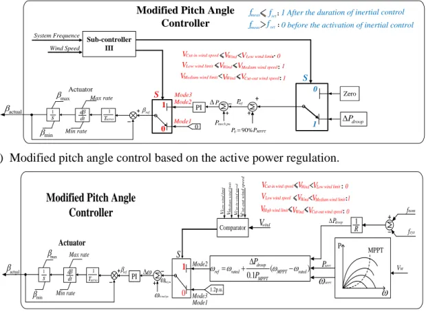
The original objective of pitch angle control in WT is to prevent the power output of generator from overloading or rotor speed from overspeed [23]. To provide a supplementary frequency regulation, the pitch control needs to be modified in terms of various wind conditions. Moreover, the primary frequency response can be effectively supplied under the high and medium wind speeds although the rotor speed is maintained as the maximum rotor speed. Meanwhile, the initial pitch angle is regulated to keep a certain power reserve. Due to the servo time constant of the pitch controller, the response of pitch control appears to be slower than that of over-rotor speed control through power electronic converter. As illustrated in Figure 2.9, two types of modified control approaches are integrated into the pitch angle controller according to different control objectives [3] .
Mode1 Pmech.pu 1 servo T d dt 1 s max Max rate Min rate P PI ref Mode2 S 0 ref P Mode3 90%P P0
Modified Pitch Angle Controller Actuator MPPT Sub-controller III 0 1 min actual Zero droop P System Frequence Wind Speed 0 1 set
fmeas f 1 After the duration of inertial control
set fmeas f
S
0 before the activation of inertial control
Wind
V VLow wind limit 0
Wind
V 1
VLow wind limit VMedium wind speed
VCut-in wind speed
Wind
V 1
VMedium wind limit VCut-out wind speed
(a) Modified pitch angle control based on the active power regulation.
Mode1 1 servo T d dt 1 s max Max rate Min rate ref Mode2 S 1.2p.u. Mode3
Modified Pitch Angle Controller
Actuator
Comparator Vwind
Wind
V VMedium wind limit 0
Wind
V
1
VHigh wind limit VCut-out wind speed VLow wind speed
V L o w w in d l im it VCu t-in w in d s p e e d C u t-o u t w in d s p e e d V VM e d iu m w in d l im it 0 1 min actual Wind
V VLow wind limit Cut-in wind speed
V
0
( )
0.1
droop
ref rated MPPT rated
MPPT P P Ref.pu PI Actual.pu Vw P MPPT 1 R droop P MPPT PMPPT fnom fsys
(b) Modified pitch angle control based on the rotor speed regulation. Figure 2.9 Schematic diagram of modified pitch angle control strategy D. Rotor Speed Control
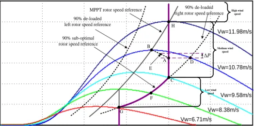
In accordance with a PMSG-WT sub-optimum power extraction curve in Figure 2.10, the WTG output is deloaded by shifting the operation point toward the left or right side of the maximum power point tracking curve during low-to-medium wind speed without hitting the rotor speed upper limit. The WTG output can be adjusted between Pdeload and Pmax by altering its rotor speed between ωdeload and ωmax [3],[16]. The operating power reference (Pref) of the deloaded WTG under the given rotor speed can be acquired using a simplified linear equation (2.14) or referring to a predefined look-up table in [66].
where, Pmax is maximum power [p.u.]; Pdel is deloaded power [p.u.]; ωr,max is DFIG rotor speed corresponding to Pmax [p.u.]; ωr,del is rotor speed at Pdel [p.u.]; ωr,meas is
measured rotor speed [p.u.].
The left sub-optimal operation point is unstable because it is more likely to cause the wind turbine to stall under the frequency event. The wind turbine is bound to operate along the right sub-optimal curve in order to maintain a stable operation when providing the frequency response over a full scope wind speeds. Another benefit of right sub-optimal operation is to enable VSWT to contribute the combined reserved active power and more kinetic energy stored in a faster rotating mass to frequency response when operating point moves from the de-loaded state to the maximum power state. Moreover, it can minimize the tear and wear losses of pitch angle during the process of system frequency regulation.
Considering that the possible rotor speed required for de-loading operation exceeds the rotor speed ωmax maximum under medium and high wind speeds, three types of wind speed modes is determined in terms of control objectives and secure operation constraints: low wind speed mode where the de-loading operation is carried out merely by rotor speed control, medium wind speed mode where the de-loading operation is conducted by combined pitch angle control and rotor speed control as well as high wind speed mode where the modified pitch angle control needs to be adopted for the de-loaded operation [19],[16],[5]. It is noted that limited kinetic energy is available for inertial response under high wind speed condition due to constant rotor speed and rated power condition [33] .
Rotor speed/p.u. 0.00 0.25 0.50 0.75 1.00 1.25 1.50 0.00 0.20 0.40 0.60 0.80 1.00 1.20 M e c h a n ic a l p o w e r/ p .u . Vw=11.98m/s Vw=10.78m/s Vw=9.58m/s Vw=8.38m/s Vw=6.71m/s 90% de-loaded right rotor speed reference MPPT rotor speed reference
A B D E C P 90% sub-optimal
rotor speed reference 90% de-loaded left rotor speed reference
F G H Low wind speed Medium wind speed High wind speed
Figure 2.1090% PMSG-WT sub-optimal operation curve
2.1.3 Secondary Frequency Control /AGC
Secondary frequency control, also called Automatic Generation Control (AGC) or Load Frequency Control (LFC), is implemented during both emergency events and normal condition [9]-[53]. The secondary frequency control starts within several tens of seconds and sustains for up to several tens of minutes [59]. This control is a minute by minute continuous response to allocate the load change among individual WTs with the purpose of maintaining both the system frequency deviation and the tie line power flow deviation as zero [47]. In figure 11, a simplified frequency control model is applied to validate the dynamic characteristics of each generation participating in the AGC regulation [71]. The AGC set-point of each WT depends on the PI controller parameters and participation factors (PFs). The optimal method to decide PFs is developed by taking into account the up/down ramp rate, operating reserves, dispatch limit and generating cost [72].
A secondary frequency controller based on a Supervisory Wind Farm Control System (SWFCS) fully utilize secondary frequency reserve to respond the command from the system operator including AGC demand (power set-point) and power flow adjustment [53],[13],[9]. Another novel control system is proposed in [73] to enable wind turbine to change the active power reference in accordance with AGC or set-point power command so as to meet the system operators' requirement. In [72], a coordinated AGC control strategy between WTs and combined heat and power plants (CHPs) is proposed to mitigate the real-time power imbalance by down-regulating the wind power production when CHPs are unable to track the required response. Due to the fast ramp rate of WTs, area control error (ACE) can be greatly reduced so as to make the system frequency more reliable and secure.
2.1.4 Tertiary Frequency Control
Compared with other frequency controls mentioned above, tertiary frequency control is a much slower power balance control with the long decision time step from the order of minutes to hours, which is activated only after the secondary control is completed [59],[62],[74]. This control method comprises dispatching actions commanded by the system operator to fulfill the reserve deployment and restoration for the WT's tertiary frequency control that enables unit commitment, economic dispatch and optimal power flow according to marketing signals or other system requirements [27]. As shown in Figure 2.11, the actual operation reference value of conventional generators and wind farms equal to the sum of AGC and economic dispatch set points. Economic dispatch usually updates this operating set point every 1-5 min while AGC does the same every