Vol.9 No.6 pp.723–730 DOI: 10.1541/ieejjia.19008074
Translated from IEEJ Transactions on Industry Applications, Vol.140 No.4 pp.265–271
Paper
(Translation of IEEJ Trans. IA)
Magnet Temperature Estimation Methodology by Using Magnet Flux
Linkage Observer for Variable Leakage Flux IPMSM
Takashi Kato
∗a)Senior Member,
Kensuke Sasaki
∗ MemberDiego Fernandez Laborda
∗∗ Non-member,Daniel Fern´
andez Alonso
∗∗ Non-memberDavid D´ıaz Reigosa
∗∗ Non-memberJ-STAGE Advance published date : October 1, 2010
This paper presents a novel methodology of magnet temperature estimation using a magnet flux linkage observer for a Variable Leakage Flux Interior Permanent Magnet Synchronous Motor (VLF-IPMSM), whose parameters vary depending on load current conditions. The magnet temperature estimation algorithm consists of a Gopinath-Style flux observer, magnet flux linkage observer, and magnet temperature estimator based on the look-up table. The estima-tion accuracy is evaluated on d-q current plane by using both a behavior model of JMAG-RT and a control model of MATLAB Simulink. Then it is shown that the proposed methodology can be applied to a VLF-IPMSM for magnet temperature estimation.
Keywords:magnetic flux linkage observer, magnet temperature estimation, variable leakage flux motor, IPMSM
1.
Introduction
In recent years, battery electric vehicles (BEV) and hybrid electric vehicles (HEV) are becoming more widespread from the viewpoint of soaring crude oil prices and the reduction of CO2emissions. In these electric vehicles powered by the
driving force of motors, there is a need for downsizing the motors to be installed in a limited vehicle layout space. Ad-ditionally, it is also necessary to convert the limited onboard energy into power with high efficiency. For these reasons, permanent magnet synchronous motors (PMSM), which are characterized by high power density and high efficiency, are often used. Further downsizing PMSM and improving the power density are in progress with the improvement in char-acteristics of rare earth magnets such as neodymium mag-nets. Because neodymium magnets have relatively large re-manence and change in coercivity (temperature coefficient) with temperature change, the coercivity is typically improved by adding heavy rare earth elements such as dysprosium (Dy) and terbium (Tb) in order to prevent demagnetization during high-temperature use.
These heavy rare earth elements are rare raw materials with the supply risk due to factors such as uneven distri-bution of production areas. It is therefore desirable to use the minimum amount required according to magnet temper-ature and strength of the reverse magnetic field. However, due to the difficulty in accurately measuring the temperature a) Correspondence to: Takashi Kato. E-mail: [email protected]
ssan.co.jp
∗Nissan Motor Co., Ltd.
1-1, Morinosato-Aoyama, Atsugi, Kanagawa 243-0123, Japan
∗∗University of Oviedo
Office 4.2.11 building 4, west Campus de Viesques 33204 Gijon, Asturias, Spain
of the magnet embedded in the rotating rotor, it is common to design materials with a certain temperature margin, pre-venting permanent demagnetization under the assumed usage conditions. Optimization of magnet amount and composition would become possible if the exact magnet temperature dur-ing an operation can be obtained, but in order to monitor in real time the temperature of the permanent magnet embed-ded in the rotor using a thermocouple, additional components such as a slip ring or a telemeter for temperature signal trans-mission are required.
Against this background, various magnet temperature es-timation methods have been proposed for high-temperature applications of permanent magnets. In Reference (1), a mag-net temperature estimation method was proposed for interior permanent magnet synchronous generators in hybrid electric vehicles, using a thermal circuit network composed of ther-mal resistances and heat capacities obtained by prior experi-ments and simulations. In this method, carrier harmonics are obtained first for three control methods: the sine wave PWM in the low-speed range, the 6-step voltage phase control in the high-speed range and the PWM over modulation in the mid-dle range. Based on these current waveforms, temperature rise per unit time was then calculated from the heat value dis-tribution under each operating condition, using a loss analysis model by 3-D FEA. Thermal resistance applied to the ther-mal network was determined by the temperature difference calculated from temperatures measured at multiple points us-ing a specimen with embedded thermocouples. In addition, this study was performed for the direct coil cooling system by Automatic Transmission Fluid (ATF). The accuracy with the estimation error of approximately 10% was achieved by experimentally obtaining the correlation between ATF tem-perature and magnet temtem-perature.
the estimation accuracy by constructing an observer to com-pare the measured and estimated temperatures of the fixed winding, in addition to the estimation by the thermal net-work. In this method, if an accurate thermal network model is constructed, a desirable temperature estimation accuracy can be obtained. On the other hand, however, it is necessary to construct an optimal lumped constant model according to the distributed parameter systems, which include actual mo-tor structure, material properties and cooling methods such as oil cooling and air cooling. Strictly speaking, these circuit constants are expected to be affected by temperature distribu-tion due to the operating point history and also by modeling errors.
In Reference (3), a method without a thermal circuit model was proposed to estimate temperature, based on the change in physical signals due to changing magnet temperature. Seen from the power supply side, PMSM can be viewed equiva-lently as a transformer model when the stator winding is con-sidered as a primary coil and the eddy current path generated inside the rotor magnet through the air gap as a secondary coil. Here, electric resistance Rmand inductance Lm of the eddy current path in the magnet, which are both circuit con-stants on the secondary side, are functions of magnet perature. Based on this, a harmonic current for magnet tem-perature estimation is superposed separately from the drive current, and the resulting change in the harmonic impedance
ZHFcan be used to estimate the magnet temperature. In the case of interior permanent magnet motors (IPM motors) that have an iron core on the magnet surface, the estimation ac-curacy of this method may be affected by the change in mag-netic saturation of the iron core depending on load conditions and also the path of the harmonic flux based on the magnet arrangement. In particular, this must be taken into considera-tion for motors whose parameters such as magnet flux linkage and inductance vary significantly depending on load condi-tions.
In this paper, we examine a novel methodology of magnet temperature estimation for a Variable Leakage Flux Interior Permanent Magnet Synchronous Motor (VLF-IPMSM)(4) (5),
whose magnetic flux linkage varies significantly in response to load current conditions and thereby expands the high-efficiency range. While it is possible to apply the previously proposed methods to VLF-IPMSM, their drawbacks are as follows: the method in Reference (1) cannot directly be ap-plied to a system that is not based on ATF; the method in Reference (2) contains thermal network modeling errors; and the method in Reference (3) will increase the non-linearity of the correlation between impedance and magnet temperature when applied for VLF-IPMSM whose motor parameters vary significantly. Therefore, in this paper, we propose a novel magnet temperature estimation method using a magnet flux linkage observer, which does not require a thermal network and is robust against parameter fluctuations. The magnet flux linkage observer consists of a Gopinath-Style flux observer ford-axis magnet flux estimation(6) (7)
and a calculator, which approximates the magnetic flux linkageλpmfrom the change in thed-axis interlinkage magnetic fluxλd when thed-axis current is changed by a minute amount ofΔid, by assuming the constantd-axis inductance during this minute change in thed-axis current.
The magnetic flux linkage in VLF-IPMSM greatly varies depending on current load states and is thereby expressed asλpm(id,iq). Magnetic temperature estimation is possible by obtaining theλpm(id,iq) characteristics at different tem-peratures in advance and comparing them with the magnetic flux linkage estimated by the magnet flux linkage observer λpm est.
In this paper, we first describe the validity of using mag-netic flux linkage for magnet temperature estimation from physical considerations, and propose a method to approxi-mate the magnetic flux linkage from thed-axis magnetic flux. Next, we construct a magnetic flux linkage observer by com-bining a Gopinath-Style flux linkage observer and a magnetic flux linkage calculator, implement a JMAG-RT-based VLF-IPMSM behavior model and perform the estimation of mag-netic flux linkage for each load current. We then compare the estimatedλpm estandλpm RT calculated by JMAG-RT, which is defined as the true value in this study, with the relationship between theλpm and magnet temperature analyzed by FEA in advance, and estimate magnet temperature at each operat-ing point in order to demonstrate the validity of the proposed method.
2.
Basic Principles of Magnetic Temperature
Es-timation in PMSM
We suppose magnet temperature estimation in PMSM without using any temperature sensors such as thermocou-ple by detecting changes in a physical quantity due to the change in magnet temperature. When magnet temperature changes, the remanenceBr changes in response (in the case of neodymium magnets, the temperature coefficient of re-manence is around−0.1∼−0.15%/K), and consequently the magnetic flux linkageλpm and the relative magnetic perme-ability in the iron coreμr also change due to magnetic sat-uration. Responding to the change of the relative magnetic permeabilityμr, the inductanceLalso changes. On the other hand, when the magnet volume resistivity ρ changes, the electrical resistanceRmof the eddy current path in the magnet changes, also resulting in change in the impedanceZmseen from the power supply side. The real part of the impedance
Zmis related to the electrical resistanceRm, and the imaginary part is to the inductanceL(3). Because these tendencies are
at-tributed to the temperature dependence of permanent magnet remanence and resistivity as well as the magnetic saturation characteristics of the iron core material, they are commonly valid in PMSM including VLF-IPMSM, which is the subject of our paper.
In a general vehicle drive motor system, detectable physi-cal quantities are current value from a current sensor, voltage command value from a motor controller, and rotation angle signal from a resolver. Using these values, it is necessary to estimate magnetic flux linkage and impedance containing magnetic temperature information. For highly accurate mag-net temperature estimation, physical quantities with larger temperature coefficients are desired. For example, Fig. 1 presents the magnet flux linkageλpm and thed-axis induc-tanceLdas functions of the magnet temperatureTmag, which are the result of FEA analysis using VLF-IPMSM, the subject of this study (details of the model are described in Section 4). While the magnet flux linkageλpmhave the sensitivity of
ap-Fig. 1. Temperature dependency ofλpmandLd
proximately −0.15%/K according to the temperature coeffi -cient of the permanent magnet, the temperature sensitivity of d-axis inductanceLd is minute. This is because, in the range where the interlinkage magnetic flux and the current is in a linear correlation, the change in dλ/diis small even when the magnetic flux density in the iron core slightly changes in response to the magnet temperature change. On the other hand, in the magnetic saturation region where the load cur-rent is large, the magnetic flux componentλpmfor the arma-ture magnetic fluxLdid becomes relatively small, the induc-tance fluctuation in response to magnet temperature change still becomes small. Therefore, in our study, we focus on the magnet flux linkageλpm, which directly changes in response to the magnet temperature change, and propose a novel tem-perature estimation method.
3.
Magnet Temperature Estimation Using a
Mag-netic Flux Linkage Observer
3.1 Estimation ofd-axis Interlinkage Magnetic Flux λd Since the magnetic flux linkageλpmis included in the d-axis interlinkage magnetic fluxλd, it is necessary to obtain thed-axis interlinkage magnetic flux value first for the esti-mation of λpm. In this paper, we use a Gopinath-Style flux linkage observer(6) (7)to perform the estimation of thed-axis
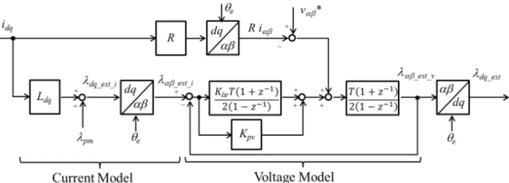
magnetic flux. This magnetic flux observer is composed of a current model and a voltage model. The structure of the observer is shown in Fig. 2.
In the current model, thed-axis magnetic flux component λd is expressed as the sum of the magnetic fluxλpmand the inductance term Ld id as shown in Eq. (1). The phase cur-rent value is detected by a curcur-rent sensor, andd-qcoordinate conversion is performed to obtain thed-qaxis current. This is then multiplied by the inductance value and added to the magnetic fluxλpmto estimate the interlinkage magnetic flux component.
Fig. 2. Gopinath-style flux linkage observer for Magnet Flux Linkage Estimation λd λq = Ld 0 0 Lq id iq + λpm 0 · · · ·(1) Because this model does not include the back electromo-tive force term and requires only the measured current value and the motor parameters acquired in advance for calcula-tion, the magnetic flux estimation is possible even in a low-speed region where the back electromotive forces are small. However, in the case where the motor parameters fluctuate depending on the current load or temperature conditions, the estimation solely based on this current model will possibly increase error.
On the other hand, in the voltage model, the interlinkage magnetic flux estimated by the current model is used as the input value for a PI controller, and the voltage command valuevαβ∗, the current value, and the winding resistance in the fixed coordinate system are obtained. Substituting them in Eq. (2), the calculated voltage value is integrated to obtain the magnetic fluxλαβin the fixed coordinate system, and the
d-axis interlinkage magnetic fluxλd is calculated by thed-q coordinate transformation.
λαβ=
(vαβ∗−Riαβ)dt· · · ·(2) The voltage model here can be seen as a feedback con-troller system that combines the plant part, a simple integra-tor, and the PI controller. The cutofffrequency, which is set from the proportional gain and the integral gain in the volt-age model, corresponds to the frequency characteristics with respect to the input of the voltage model (i.e., the output of the current model). In the region above the cutofffrequency, the magnetic flux due to the current model gradually atten-uates and transitions to the estimated value by the voltage model(8). In this paper, an observer that combines the
cur-rent model and the voltage model is applied and we assume magnet temperature estimation in the region for the rotational speed where the output of the voltage model is dominant. For this reason, we performed our study with constant values for motor parameters in the current model despite a larger error due to parameter fluctuations.
3.2 Extraction of the Magnetic Flux Linkage λpm
Component from thed-axis Interlinkage Magnetic Flux λd In general, for PMSM, the magnetic flux linkageλpm and the d-axis inductance Ld are assumed to be constant, and thed-axis interlinkage magnetic fluxλd is expressed us-ing Eq. (1). However, exceptions are when it is not trivial to ignore the change in remanence in response to magnet
temperature change or the influence of magnetic saturation due to the current load, as well as for the case of motors whose parameters significantly vary depending on the cur-rent load such as VLF-IPMSM, the subject of this paper. In such a case, the first and the second terms in Eq. (1) must be expressed as functions of thed-qaxis current and magnet temperature as shown in Eq. (3).
λd=λpm(Tmag,id,iq)+Ld(Tmag,id,iq)id· · · (3) However, only the total magnetic fluxλd is detectable by the actual motor, and it is difficult to estimate the magnet temperature Tmag directly from the sum of the first and the second terms that are both functions ofTmag. We therefore consider a method to extract only the magnetic flux linkage λpmby approximation.
Figure 3 illustrates the scheme of the relationship between
d-axis current and d-axis magnetic flux. We suppose su-perposing a minute d-axis current Δid on arbitrary current load state id andiq. Assuming the changes in λpm andLd caused by the superposition are negligible, the change in the
d-axis magnetic flux λd can be assumed to depend only on the change in the second term of Eq. (3). On the other hand, with the superposition ofΔid, thed-axis magnetic fluxλd’ is expressed as shown in Eq. (4).
λd=λpm(Tmag,id,iq)+Ld(Tmag,id,iq)(id+Δid)· · · · ·(4) Rearranging Eq. (3) and Eq. (4) leads to Eq. (5).
λd λd = 1 id 1 id+ Δid λpm(Tmag,id,iq) Ld(Tmag,id,iq) · · · ·(5) By further rearranging Eq. (5) forλpm, Eq. (6) is obtained.
Fig. 3. Definition ofd-axis flux approximation
Fig. 4. Block diagram of magnet temperature estimation using magnet flux linkage observer λpm(Tmag,id,iq) Ld(Tmag,id,iq) =−1 Δid id −(id+Δid) −1 1 λd λd · · · · ·(6) λpmin Eq. (6) is equivalent to the estimated magnetic flux λpm est. The equation extracted for λpm est is expressed in Eq. (7).
λpm est= − 1
Δid{i
dλd−(id+ Δid)λd}· · · ·(7) By definingid’=id + Δid and rearranging Eq. (7), Eq. (8) is obtained, which is used for the interlinkage magnetic flux calculator in our study.
λpm est= λd− id id λd 1− id id · · · ·(8) In FEA, by substituting thed-axis interlinkage magnetic fluxλd calculated from the winding flux linkage, and thed -axis currentid in Eq. (6), the magnetic flux linkageλpmcan be obtained at any magnetic temperatureTmag andd-qaxis currentsid andiq. In addition, for control simulation and in actual environment, the magnetic flux linkageλpm estcan be calculated by estimatingλd estandidusing the magnetic flux observer introduced in Section 3.1 and substituting them in Eq. (6).
3.3 Magnet Temperature Estimation by the Magnetic
Flux Linkage Observer As discussed in the previous
section, the approximation of the magnetic flux linkageλpm at the currentidq, using thed-axis interlinkage magnetic flux λdandλd’ under the current condition that differs by a minute amountΔid, would enable the magnet temperature estimation through the comparison with previously obtainedλpm(Tmag, id,iq). A block diagram of the magnet temperature estima-tion algorithm is presented in Fig. 4. For the feedback control system consisting of the plant motor model and the PI con-troller, a superposing device that generates a minuted-axis current Δid is placed so that it will add Δid to the current command value according to the trigger signal. The voltage command valuevdq∗, the current valueidq∗and the rotational angle signalθeare obtained via the PI controller and input to the magnetic flux observer to calculateλd estandλd est’.
Fig. 5. Magnet temperature estimation scheme
magnetic flux linkage calculator, the magnetic flux linkage λpm estis calculated according to Eq. (6).
Next, this calculatedλpm estis input to the magnet temper-ature estimator. The magnet tempertemper-ature estimator has pre-viously obtainedλpm(id,iq) at different magnet temperatures, which are stored as temperature coefficient mapping infor-mation. Once the voltage command value is determined, the relationship between the magnetic fluxλpm and the magnet temperatureTmagis determined as shown in Fig. 5, enabling the estimation ofTmagfromλpm estobtained by the magnetic flux linkage calculator.
4.
Principle Validation by Simulation
4.1 Understanding the Relationship between Magnet
Temperature and Magnet Fluxλpm by FEA We
per-form analysis using VLF-IPMSM(5), which has variable
leak-age flux characteristics, as a model for principle validation. Schematic drawings and main specifications of VLF-IPMSM are presented in Fig. 6 and Table 1, respectively. As shown in Fig. 6, VLF-IPMSM has a magnetic flux bypass structure between the magnetic poles, and consequently the magnetic flux linkage λpm varies substantially depending on current amplitude and phase. We used-qaxis currentid pand mag-net temperatureTmagas parameters to calculate the interlink-age magnetic fluxλdunder each analysis condition by mag-netic field analysis. By using this obtained λd and Eq. (6), the magnetic flux linkageλpmis calculated, and relationships betweenλpmand each parameter are examined.
Analysis condition: Rotation speed: 3000 min−1
d-qaxis current: 0 to 600 A (increment by 100 A; 7 levels) Magnet temperature: 20 to 140◦C (increment by 30◦C; 5 lev-els)
The magnetic flux linkageλpmunder each current and tem-perature condition is plotted in Fig. 7. Under the zero-load condition when idq = 0, the magnetic flux linkage λpm is suppressed due to the short circuit of magnetic flux via the magnetic flux bypass sections. In contrast,λpmincreases as theq-axis current increases. This trend is consistent among different magnet temperature conditions, and theλpm maps at different temperature conditions do not cross each other throughout the entire current conditions within the operating range. For permanent magnets and magnetic steel sheets typ-ically used in PMSM, the sign of remanence and magnetic permeability gradients in response to temperature change does not reverse within the operating temperature range and under operating point conditions. It is therefore safe to as-sume that λpm maps at different temperature conditions for general PMSM systems other than this paper will not cross
Fig. 6. Schematic drawings of VLF-IPMSM Table 1. Specifications of the VLF-IPMSM
Fig. 7. Magnet flux linkage on d-q plane by FEA
each other either. This suggests that the estimation of magnet temperature is possible by comparingλpm est, which is esti-mated from thed-qaxis current values and the magnetic flux observer, with the mapping data in Fig. 7.
A minute d-axis current Δid was set at 1% of the com-mand value current in the prior FEA analysis for obtaining λpm characteristics in this study. In the actual machine,Δid is set at an appropriate value in consideration of factors such as noise levels and errors in the current sensor. In order to reduce analysis error,λpmwas obtained by averaging values obtained from Eq. (6) for each ofλd at the referenced-axis currentidand twod-axis interlinkage magnetic fluxλd’|id+Δid andλd”|id−Δid atid ±Δid. Based on these results in Fig. 7, the distribution of temperature coefficient at 20∼140◦C under any current condition was calculated, and it showed almost uniform characteristics as seen in Fig. 8.
Fig. 8. Thermal coefficient map on d-q plane
Fig. 9. idqcurrent waveforms
4.2 Operation Validation of the Magnetic Flux
Ob-server using the VLF-IPMSM Model In order to
val-idate the operation of the magnetic flux observer, we build a behavior model using a JMAG-RT spatial harmonic model (JSOL Corporation) for the VLF-IPMSM shown in Fig. 6. This model is based on a FEA model and made into an LUT by calculating in advance the interlinkage magnetic flux un-der each condition with parameters of current amplitude and phase. It is configured to enable the output of the magnetic flux information in response to the voltage command value generated by the circuit simulator. The model is incorporated into the magnetic flux observer in Fig. 4 to estimateλd(id,iq) under an arbitrary current conditionidq. The estimatedλd(id, iq) is then input to the magnetic flux linkage calculator for estimatingλpm.
In the JMAG-RT model used in this study, we set magnet temperature at 20◦C and thed-qcurrent values in the range between 0∼600 A. To simplify the gain setting described in Section 3.1, we focus on the open-loop transfer function in the current model and the gain is set to have the cutoff fre-quency of 5 Hz (with rotation speed below 100 min−1). As
mentioned earlier, as we keep the motor parameters in the current model constant in this study, the error due to magnetic flux in the current model is expected to increase in the low-speed region below the cutofffrequency. However, it should not be an issue in practice because, in the vehicle drive mo-tors studied in this paper, the main reason for magnet temper-ature increase is considered to be eddy current loss in magnet due to slot harmonics in the medium- to high-speed region where the voltage model output becomes dominant.
For the current command value, withidqas the reference, the waveform superposed with ±Δid for estimation of mag-netic flux linkage as shown in Fig. 9 is applied to thed-axis current. We setΔid as 5% of the reference current id. The currents of id,id −Δid andid +Δid are applied stepwise in this order at 100 ms intervals starting at t=300 ms. The
av-Fig. 10. Estimation result of d-axis flux observer
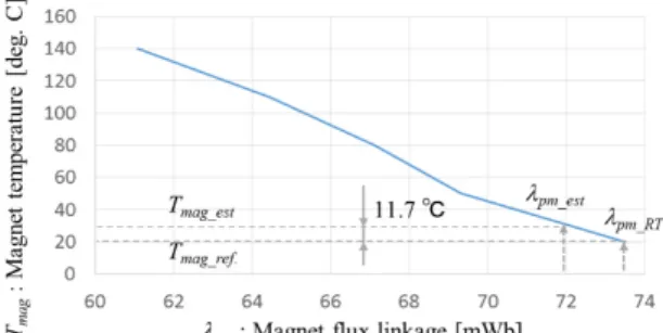
Fig. 11. Magnet temperature estimation result
erage value in each section is calculated as estimated-axis magnetic fluxλd est.
As an example of the analysis results, Fig. 10 shows the estimated thed-qaxis magnetic fluxλd est by the magnetic flux observer and the magnetic flux output λd RT from the behavior model JMAG-RT atiq =200 A andid =−200 A. The estimated magnetic flux responsively follows the step-wise changes ofd-axis current command value. In this sim-ulation for principle validation, when the JMAG-RT output ofd-axis magnetic flux; 45.09 mWb is regarded as the true value and compared with the estimated value by the mag-netic flux observer; 45.05 mWb, the result demonstrates that the estimation with an error below 1% is achieved under this current condition. Usingλd, λd est’ andλd est” under this condition, the estimated magnetic fluxλpm from Eq. (6) is 71.92 mWb. Comparing it with the true value of 73.56 mWb, the estimation was achieved with an error of approximately
−2.2%. We next examine the influence of the estimation er-ror of magnetic flux on the accuracy of magnet temperature estimation. Figure 11 presents the relationship between mag-net temperature and magmag-netic flux linkage under the current condition in Fig. 10. The magnet temperature estimated from the magnetic flux linkageλd estcalculated by the observer is compared with the magnet temperature setting of 20◦C in the JMAG-RT model as the true value, and the estimation was with an error of approximately 11.7◦C.
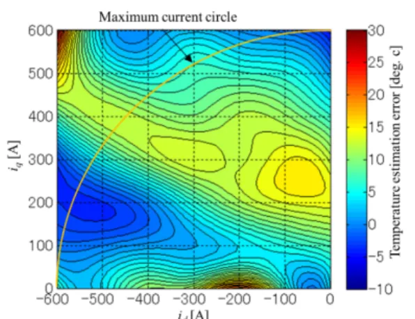
Similarly, for the input conditions at idq = 0∼600 A, λpm est(Tmag, id, iq) was calculated for each condition, and the obtained result of magnet temperature estimation error mapping is shown in Fig. 12.
These results show that the magnet temperature estimation was achieved with an error ranging about−3∼23◦C within the current limit circle, although the estimation error varies depending on the current condition. Based on this, for the VLF-IPMSM, where the motor parameters significantly fluc-tuate depending on the current load state, we confirmed the validity of the magnet temperature estimation method by the
Fig. 12. Magnet temperature estimation result on d-q plane magnet flux linkage observer proposed in this paper.
5.
Conclusion
In this paper, we showed from our theoretical consideration that magnetic flux linkage is an effective physical quantity to evaluate for magnet temperature estimation, and proposed a novel methodology of magnet temperature estimation using a magnet flux linkage observer.
For the VLF-IPMSM in which the motor parameters fluc-tuate significantly depending on the current load, the pro-posed method was examined with a high-precision motor model and control simulation by magnetic field analysis. As a result, we showed good temperature estimation accuracy in the range of idqoperation conditions, demonstrating the va-lidity of this method.
References
( 1 ) M. Kamiya, H. Awata, T. Miura, Y. Yagyu, T. Kosaka, and N. Matsui: “Per-manent Magnet Temperature Analysis Considering PWM Carrier Harmonics for Interior Permanent Magnet Synchronous Generator in Hybrid Vehicles”, IEEJ Trans. on IA, Vol.127, No.12, pp.1238–1244 (2007) (in Japanese) ( 2 ) Y. Imanishi and S. Nishiguchi: “Development of Temperature Estimation for
Motor Magnet of Electric Vehicle”,SAEJ Trans., Vol.45, No.5, pp.841–845 (2014)
( 3 ) D. Reigosa, D. Fernandez, H. Yoshida, T. Kato, and F. Briz: “Permanent-Magnet Temperature Estimation in PMSMs Using Pulsating High-Frequency Current Injection”, IEEE Trans. on Industry Applications, Vol.51, No.4, pp.3159–3168 (2015)
( 4 ) T. Kato, H. Hijikata, M. Minowa, K. Akatsu, and R.D. Lorenz: “De-sign Methodology for Variable Leakage Flux IPM for Automobile Traction Drives”,IEEE Trans. on Industry Applications., Vol.51, No.5, pp.3811–3821 (2015)
( 5 ) T. Kato, K. Sasaki, T. Matsuura, and T. Tanimoto: “Principle of Variable Leakage Flux IPMSM Using Arc-shaped Magnet Considering Variable Mo-tor Parameter Characteristics Depending on Load Current”, IEEE Energy Conversion Congress and Exposition (2017)
( 6 ) J.S. Lee, C.-H. Choi, J.-K. Seok, and R.D. Lorenz: “Deadbeat-Direct Torque and Flux Control of Interior Permanent Magnet Synchronous Machines With Discrete Time Stator Current and Stator Flux Linkage Observer”, IEEE Trans. on Industry Applications, Vol.47, No.4, pp.1749–1758 (2011) ( 7 ) P.L. Jansen and R.D. Lorenz: “A physically insightful approach to the design
and accuracy assessment of flux observers for field-oriented induction motor drives”,IEEE Trans. on Industry Applications, Vol.38, No.5, pp.1334–1343 (2002)
( 8 ) A. Shinohara and K. Yamamoto: “Estimation error analysis of stator flux observer for DTC-based PMSM drives”, Proceedings of International Power Electronics Conference 2018 (IPEC-Niigata 2018), pp.1308–1314 (2018)
Takashi Kato (Senior Member) received the B.S. degree in me-chanical system engineering from Kansai University, Osaka, Japan, in 1997, and received the Ph.D. de-grees from Shibaura Institute of technology in 2015. He joined Nissan Motor Co., ltd. in 1997, and he joined Nissan Research Center in 2001. He has con-tributed to the electric machine design and control. He was a visiting researcher in the Wisconsin Electric Machines and Power Electronics Consortium (WEM-PEC), at University of Wisconsin Madison from 2010 to 2012. He is a research manager of EV system laboratory in Nissan re-search center. His rere-search interests are electric motor design, control and power electronics devices. Dr. Kato is a member of Institute of Electrical and Electronics Engineers (IEEE), Institute of Electrical Engineers of Japan (IEEJ), Society of Automotive Engineers of Japan (JSAE) and the Japan So-ciety of Mechanical Engineers (JSME).
Kensuke Sasaki (Member) received the B.S. and M.S. degrees from Yokohama National University, Yokohama, Japan, in 2003 and 2005, respectively, all in electrical engineer-ing. In 2005, he joined the Nissan Research Center, Atsugi, Japan, where he contributed to inverter circuit design, converter circuit design and control. From 2014 to 2016, he was a Visiting Engineer with the Wisconsin Electric Machines and Power Electronics Consortium (WEMPEC), University of Wisconsin-Madison, WI, USA. He is currently with the Electric Vehicle System Laboratory, Nissan Motor Co., Ltd. Atsugi, Japan. His re-search interests include electric motor design and control. Mr. Sasaki is a member of Institute of Electrical Engineers of Japan (IEEJ).
Diego Fernandez Laborda (Non-member) received the B.S. degree in industrial electronic engineering in 2016 and the M.S. degree in electric energy conversion and power electronics engineering in 2018, from the Univer-sity of Oviedo, Gijon, Spain. He has been a re-searcher with the Department of Electrical, Elec-tronic, Computers and Systems Engineering, Univer-sity of Oviedo since 2018. He is currently working towards the Ph.D. degree in electrical engineering. His research interests include electric machines and power electronics for electric vehicles, wireless measurement systems and digital signal processing.
Daniel Fern´andez Alonso (Non-member) received the M.S. degree in power electronic engineering and the Ph.D. degree in Electrical Engineering from the University of Oviedo, Gijon, Spain, in 2013 and 2017 respectively. He was an Intern at the Nissan Advanced Technology Cen-ter in 2013 and a visiting student at the University of Sheffield in 2015. He was awarded a fellowship of the Personnel Research Training Program funded by the Regional Ministry of Education and Science of the Principality of Asturias in 2013 and he was the recipient of four IEEE Industry Applications Society Conference prize paper awards. His research interests include design, monitoring and diagnostics of electric machines, control of electric drives and magnetics.
David D´ıaz Reigosa (Non-member) was born in Spain 1979. He re-ceived the M.E. and Ph.D. degrees in electrical engi-neering from the University of Oviedo, in 2003 and 2007, respectively. He is currently and Associated Professor in the Electrical Engineering Department, University of Oviedo. From 2004 to 2008, he was awarded and fellowship of the Personnel Research Training Program funded by Regional Ministry of Education and Science of the Principality of Asturias. He was a visitor scholar at the Wisconsin Electric Ma-chines and Power Electronics Consortium, University of Wisconsin, Madi-son, in 2007. He was a visitor professor at the University of Sheffield (UK), Electrical Machines and Drives Group, in 2016. He was the recipient of nine IEEE Industry Applications Society Conference and IEEE Energy Con-version Congress and Exposition prize paper awards. His research inter-ests include sensor-less control of induction motors, permanent magnet syn-chronous motors and digital signal processing.