TrueAlarm
®Fire Alarm Controls
UL, ULC Listed;
Fire Alarm Controls
FM, CSFM, and
4100 and 4120 Series Addressable
MEA (NYC) Approved*
Detection and Control Systems
STANDARD FEATURES
• UL Listed for:
– Fire Detection and Control (UOJZ)
– Proprietary Alarm Units - Burglar (APOU)
– Process Management Equipment (QVAX)
– Smoke Control Service (UUKL)
• Wide viewing angle, 80 character super-twist LCD
• Selectable for maintained display of first alarm
• Expandable up to 1000 points
• Dedicated supervisory service indicator and acknowledge
• Nonvolatile flash EPROM memory
• Battery supervision (low/no battery)
• Power-limited operation per NEC 760 (module
dependent)
SOFTWARE FEATURES
• WALKTEST™ system test**
• Four operator access levels
• 600 event historical log
• Individual circuit disconnect/disable
• Programmable:
– Alarm verification by zone or point
– Selective signaling and/or relay control
– Zone coding (PNIS)
– Signal silence reminder
OPTIONAL FEATURES
• Voice communications and firefighter’s phones
• Interface to remote:
– MAPNET II® addressable devices and TrueAlarm®
analog sensors**
– MINIPLEX® Transponders
– TrueAlert™ Addressable Controllers
– 4-20 mA Analog Monitor ZAMs (AMZs)
– Supervised LED and LCD serial annunciators
• Release control operation OPTIONAL MODULES (partial list)
• 4120 Network interface
• Class A or Class B IDCs and NACs
• Control relays with feedback
• Dial-in service modem
• RS-232 interface to remote printer or CRT/keyboard
• Panel mount printer
• Internal DACTs, serial or contact closure
• Decoder module for coded circuit interface
• Simplex 2120 interface
• Expansion power supplies and battery chargers
4100 FIRE ALARM CONTROL PULL TO OPEN DOOR
EMERGENCY OPERATING INSTRUCTIONS ALAR M OR TROUBLE CONDITION: - SYSTEM INDICATOR FL ASHING, TONE ON. TO ACKNOWL EDGE: - PRESS "AC K" LOCATED UND ER FLASHING IND ICATOR . - REPEAT OPERATION UNTIL ALL REPORTS ARE AC KNOWLEDGED. TO SILENCE ALARM SIGNALS: - PR ESS "ALARM SILENC E". TO R ESTORE SYSTEM TO NORMAL: - PRESS "SYSTEM RESET." - PRESS "AC K" TO SILENCE TONE DEVICE. OPERATOR INTERFACE PANEL FIRE ALARM SYSTEM TROUBLE SIGNALS SILENCED POWER ON PRIORITY 2 ALARM SYSTEM SUPERVISORY SYSTEM IS NORMAL 12:35:15 am MON 29 JAN 96 ACKNOW LEDG E TBL AC K AC K SUPV ACK ALARM AL ARM ACK SILENCE ALARM RESET SYSTEM
4100/4120 Series Fire Alarm Control Panel with Optional Voice Control
INTRODUCTION
Simplex 4100/4120 Series Fire Alarm Detection and Control Panels provide an extensive and powerful feature list to satisfy a wide variety of applications and local code requirements. They are on-site programmable to provide mapping logic for inputs and outputs and for custom labeling additions and revisions. Their flexible site-specific software features can be quickly and securely generated, modified, and archived by trained service personnel using computer based programming tools. With this flexibility, last minute changes can be made on-site, minimizing delays in job completion. Monitor and control point expansion is available up to a maximum of 1000 points in any combination of IDCs, NACs, auxiliary control relays, and addressable devices. Annunciation capacity is up to 2000 points.
* This product has been approved by the California State Fire Marshal (CSFM) pursuant to Section 13144.1 of the California Health and Safety Code. See CSFM Listings 7165-0026:160 and 7170-0026:187 for allowable values and/or conditions concerning material presented in this document. It is subject to re-examination, revision, and possible cancellation. Accepted for use – City of New York Department of Buildings – MEA35-93E. Applicable FM approval information is available on request. Additional listings may be applicable, contact Simplex for the latest status.
** WALKTEST system test is protected under US Patent No. 4,725,818. MAPNET II addressable communications is protected under U.S. Patent No. 4,796,025. TrueAlarm analog detection is protected under U.S. Patent No. 5,155,468 and 5,173,683.
NOTE: The features described in this document assume operation with revision 9 software.
Detailed information about 4120 Network operation is found in data sheet S4120-0001. 4100 Series control panels become 4120 Series control panels when equipped with a 4120 Network interface and the required network programming.
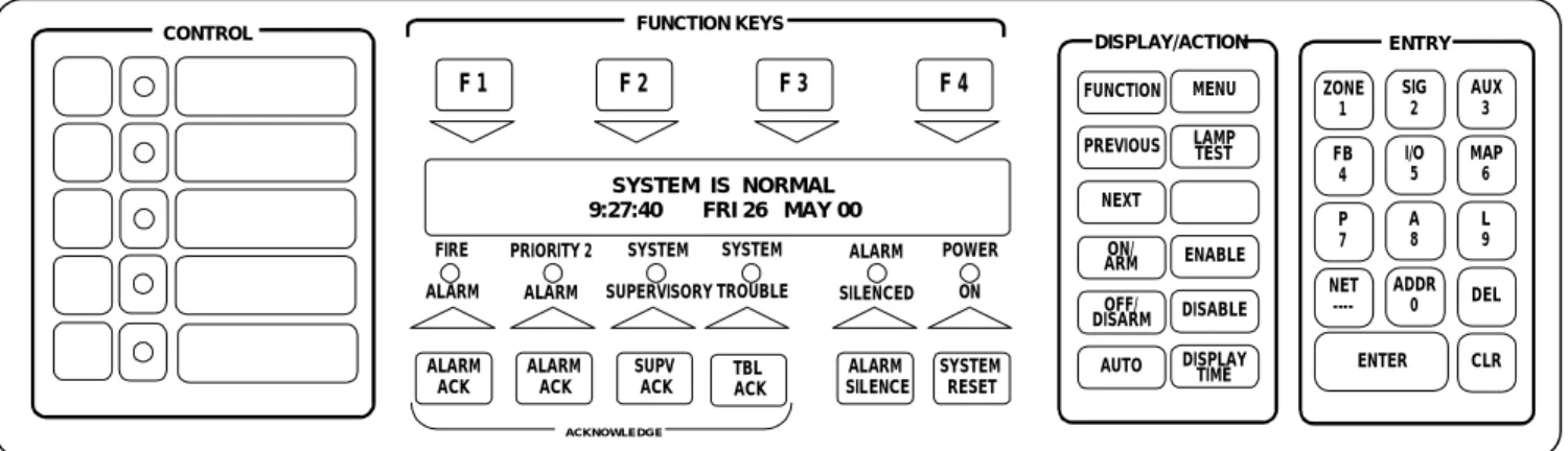
OPERATOR INTERACTION
Primary Operator Functions. The 4100 operator
panel maximizes the performance of primary fire alarm functions by displaying only the indications and interaction switches required for responding to emergency situations (see Figure 1 below).
POWER ON
EAST WING, THIRD FLOOR, AREA 19, SMOKE Smoke Detector FIRE ALARM
ALARM ACK ALARM ACK SUPV ACK TBL ACK ALARM SILENCE SYSTEM RESET FIRE ALARM ACKNOWLEDGE SYSTEM TROUBLE ALARM SILENCED PRIORITY 2 ALARM SYSTEM SUPERVISORY
FIGURE 1. Primary Operator Functions
with Typical Alarm Display
Indications. Alarm, supervisory, and trouble conditions
are indicated at the operator’s panel by dedicated LEDs and a local tone-alert. An 80 character (2 lines x 40 characters) alphanumeric super-twist liquid crystal display provides information concerning point status (alarm, trouble, supervisory, etc.), type of alarm (smoke detector, manual station, waterflow supervisory, etc.), a custom location label, and number of alarms and other conditions in the system. The top line as shown in Figure 1 would be the custom label for this alarm point. (If first alarm display is selected, status count appears after alarms are acknowledged.)
First Alarm Display. When selected for maintained
display of the first alarm, and if multiple alarms occur, the first alarm will remain displayed until acknowledged. The information shown in Figure 1 will alternate
approximately once per second with the second information line of the first alarm. A typical second line for the alarm shown would be:
EAST WING, THIRD FLOOR, AREA 19, SMOKE Press <Alarm Ack> to acknowledge
Switch Operation. Alarm, supervisory, and trouble
conditions have dedicated acknowledge push-button switches. Operation of the appropriate acknowledge switch silences the tone-alert with the LED remaining illuminated until all conditions in that category are restored to normal.
The 4100 can be programmed to perform a “global acknowledge” where a single push of the appropriate acknowledge switch will silence the tone-alert for all points in that condition. It can also be programmed for individual acknowledgment of each point in an abnormal condition, as well as their restoration. Both operations are in accordance with the requirements of NFPA 72, the National Fire Alarm Code.
Notification appliances can be silenced by pressing the ALARM SILENCE switch. Pressing the SYSTEM RESET switch restores the system to the normal operation mode. The system tone-alert can be
programmed to resound at user specified time intervals to serve as an “active status reminder” when a trouble condition remains in the system and the audible trouble signal has been silenced.
Additional Operator Function Keys. For increased
functionality, additional operator keys are available by opening the access door (see Figure 2 below). The FUNCTION KEYS, DISPLAY/ACTION keypad, and the ENTRY keypad are the operator interface sections that are not essential in a fire emergency situation. These functions are presented in a self-directing manner and include: circuit/device ENABLE or DISABLE, control point turn ON or OFF, DISPLAY HISTORICAL LOGS, etc.
Operator access is determined by four passcode protected security levels. Level 1 allows routine actions while level 4 is reserved for trained technician service access. Access in levels 2, 3, and 4 is selectable and passcode protected to ensure proper authorization for that level's control access. Passcode log-ins are stored in the history log for access review.
Display Action and Entry Keypads allow operators
(with proper access levels) to perform controlling functions to system zones, NACs, and auxiliary control relays, or to gain access for system information. DISABLE allows a specific circuit or a specific addressable device to be disconnected from the system to isolate a problem. A trouble condition will occur as a reminder of the action taken. ENABLE followed by ENTER restores the circuit or device to active status in approximately 60 seconds. The display will count down the remaining time and will warn the operator if the circuit to be enabled will cause an alarm. The NET key is used to display 4120 Network point data located at other network panels.
POWER ON SYSTEM IS NORMAL 9:27:40 FRI 26 MAY 00 ALARM ACK ALARM ACK SUPV ACK TBL ACK ALARM SILENCE SYSTEM RESET FIRE ALARM ACKNOWLEDGE SYSTEM TROUBLE ALARM SILENCED PRIORITY 2 ALARM SYSTEM SUPERVISORY CONTROL FUNCTION MENU DISPLAY/ACTION
PREVIOUS LAMPTEST NEXT ON/ ARM ENABLE OFF/ DISARM DISABLE AUTO DISPLAY TIME ZONE 1 SIG 2 AUX 3 ENTER CLR ENTRY FB 4 I/O 5 MAP 6 P 7 A 8 L 9 NET ----ADDR 0 DEL F 1 F 2 F 3 F 4 FUNCTION KEYS
OPERATOR INTERACTION (Continued) Control Keypad. CONTROL identifies five
programmable switches with associated LEDs. Possible applications are: city disconnect, door holder bypass, manual evacuation, elevator capture bypass, etc. Control switches can be individually passcode protected such that only certain access level operators can perform that function (refer to Figure 3 below).
CITY DISCONNECT MANUAL EVAC ANY CUSTOM CONTROL CONTROL DOOR HOLDER ELEVATOR BYPASS
Typical Indicating LED
Typical Control Switch Provision for Custom Labels
FIGURE 3. Control Key Detail
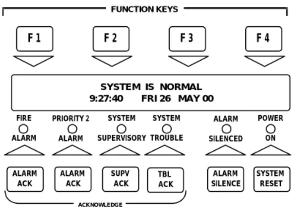
POWER ON SYSTEM IS NORMAL 9:27:40 FRI 26 MAY 00 ALARM ACK ALARM ACK SUPV ACK TBL ACK ALARM SILENCE SYSTEM RESET FIRE ALARM ACKNOWLEDGE SYSTEM TROUBLE ALARM SILENCED PRIORITY 2 ALARM SYSTEM SUPERVISORY F 1 F 2 F 3 F 4 FUNCTION KEYS
FIGURE 4. Function Key Detail
Function Keys. FUNCTION KEYS identifies the “soft”
keys F1 through F4 whose functions vary within each Main Menu Option. Each key's function is described on the top line of the display. For example, in the
DISPLAY HISTORICAL ALARM LOGS FUNCTION menu, pressing the F2 key will display the most recent alarm event stored in the history log (see Figure 4 above).
MODULE DESCRIPTIONS MASTER CONTROLLER MODULE
The 4100 Master Controller Board provides system control, synchronization, and supervision of all
modules, continuously scanning each module for status changes. Features include the following:
• Operator’s Panel with LCD and operator keys
• SPDT Auxiliary Trouble Relay rated 2 A @
30 VDC, resistive loads
• City Circuit Connection, 24 VDC remote station
(reverse polarity), local energy, shunt master box, or a Form “C” contact output
• Battery Charger for up to 110 Ah batteries:
– Batteries up to 33 Ah mount in the bottom of the
cabinet, batteries larger than 33 Ah mount external to the cabinet
– Compatible with lead acid or NiCad batteries
• Intelligent Power-Limited Power Supply:
– Two isolated outputs of 4 A each at 28.5 VDC when
AC powered (24 VDC during battery operation)
– Tap “B” provides 4 A for general purpose NAC and
control power (NOTE: This output is not available when charging 110 Ah batteries.)
– Tap “A” provides panel power with the remainder
available for NACs controlling “clean” loads with controlled inrush current and proper transient suppression
– LCD readout of system voltage and current, and
battery voltage and current
– Optional 12 VDC converter (4100-0019), rated 2 A
@ 12 VDC, requires 1.1 A max from 28 VDC
– AC input is 6 A @ 120 VAC, 3 A @ 240 VAC,
50/60 Hz
REDUNDANT MASTER CONTROLLER OPTION (4100-7023) Provides monitored dual control with
automatic switch-over hardware.
INITIATING DEVICE CIRCUITS (IDCs) (4100-5000 Series):
– Eight circuit zone modules provide system
expansion as Style B (Class B) or Style D (Class A) Operation
– Capable of supporting UL listed compatible, two-wire
smoke detectors and electronic heat detectors plus normally open contact devices (manual stations, mechanical heat detectors, etc.)
– Accepts mechanical coded Inputs
NOTIFICATION APPLIANCE CIRCUITS (NACs) (4100-4000 Series):
– Two, four, or six circuit modules provide system
expansion as Class B (Style Y) or Class A (Style Z)
– Supervised for opens, grounds, and wire-to-wire
shorts
– Dual and Triple channel modules have integral
switching relays for selecting the proper audio channel output
– Outputs can be programmed for temporal pattern or
march time pattern
– NACs are rated as: 2 A @ 24 VDC; 50 W @
25 VRMS or 100 W @ 70 VRMS for speaker circuits; or up to six firefighter telephones (including master)
GENERAL ENVIRONMENTAL OPERATING SPECIFICATIONS
Humidity...85% Noncondensing Temperature ... 32° to 120° F (0° to 49° C)
MODULE DESCRIPTIONS (Continued)
DUAL RS-232 COMMUNICATIONS MODULE (4100-0113):
– Each module provides two RS-232 ports for
connection to CRT/keyboards (terminals), printers, or other approved compatible applications
– Up to five RS-232 ports are supported per 4100
control panel with two ports (total) being selected as CRT/keyboards
– Each port can be vectored by event category
– Up to three ports total can be configured to
communicate with a host 2120 Multiplex System using 2-wire, 2120 communications (DC Comm)
– Module option 4100-0137 is available to provide
Style 7, RS-232, 2120 communications
STYLE 7, 2120 (DC COMM) INTERFACE MODULE (4100-0123):
– Maintains 2120 communications during a
wire-to-wire short fault condition
– Includes primary, secondary, and transmit status
indicators
AUXILIARY CONTROL RELAYS:
– Built-in fuse protection per contact
– Feedback tracks on/off status of remote devices
– 4100-3001, Four CPU controlled relays, DPDT
contacts rated for 2 A @ 24 VDC, or 1/2 A @ 120 VAC, inductive
– 4100-3002, Four CPU controlled relays, DPDT
contacts rated 10 A @ 24 VDC or 240 VAC maximum, inductive
– 4100-3003, Eight CPU controlled relays, SPDT
contacts rated 3 A @ 24 VDC or 120 VAC, resistive
EXPANSION POWER SUPPLY, POWER-LIMITED, 120 VAC INPUT (4100-1108):
– 8 A, (two taps of 4 A each) filtered, unregulated
24 VDC output for standard peripheral devices
– AC input is 2.5 A @ 120 VAC, 60 Hz
MINIPLEX® REMOTE INTELLIGENT POWER
SUPPLY, POWER-LIMITED (4100-0117):
– Tap “B” provides 4 A at 28.5 VDC for general
purpose NAC and control power
– Tap “A” provides remote module power, 4 A
maximum, 2 A is typically available for “clean” loads with controlled inrush currents and proper transient suppression (actual available power depends on remote module requirements)
– 4 A for battery charging (lead acid batteries only)
– Addressable electronics communicate status,
voltage, and current information for viewing at the panel LCD. Operator panel can be used to control output taps.
– AC input is 6 A @ 120 VAC, 3 A @ 240 VAC,
50/60 Hz
TIME: 1:56:10 custom title USER: 1 DATE: WED 9 OCT 96 Port 1 Card 5 A ACCESS: 1 ALARMS: 2 TROUBLES: 0 SUPERVISORIES: 0 1:42:05 PM WED 9 OCT 96 1ST FLOOR EAST WING
SMOKE DETECTOR ALARM 1:55:16 PM WED 9 OCT 96 1ST FLOOR EASTWING
PULL STATION ALARM
PF1= Ack, PF2= Silence, PF3= System Reset, PF4= Login>
Typical 4100, RS-232 Connections
NONPOWER-LIMITED EXPANSION POWER SUPPLIES
Power
Supply Input Output
4100-0105 2 A @ 120 VAC, 60 Hz 4100-0115 1 A @ 240 VAC, 50/60 Hz 5 A @ 24 VDC ± 5%, for regulated peripheral power 4100-0108 2.5 A @ 120 VAC, 60 Hz 4100-0118 1.25 A @ 240 VAC, 50/60 Hz 8 A @ 24 VDC (two taps of 4 A each) filtered, unregulated
ADDITIONAL BATTERY CHARGERS:
– Charges up to 110 Ah batteries, lead acid or NiCad
– Monitors for AC power failure, low/no battery, and
high battery level
– 120 VAC, 60 Hz model 4100-0104 requires 2 A input
– 240 VAC, 50/60 Hz model 4100-0114 requires 1 A
input
4100-0124 ENHANCED BATTERY CHARGER:
– Charges up to 110 Ah batteries, lead acid or NiCad
– Manual switches for high rate charge and AC
disconnect
– LEDs for AC fail/disconnect, low/no battery, and high
battery level
– Meters to indicate battery voltage and charging
current, 0-50 VDC voltmeter, 0-5 A ammeter
– AC input is 2 A @ 120 VAC
4120 NETWORK INTERFACE:
Model 4120-6014 provides a modular interface with media options of:
– 4120-0142, for wired data
– 4120-0143, for fiber optics
– 4120-0144, for modem connections
– Refer to data sheet S4120-0003 for details
Physical Bridge Modules provide extended modem
connection flexibility with choice of:
– Style 4 communications,4120-6023
– Style 7 communications, 4120-6024
MODULE DESCRIPTIONS (Continued) ONE-WAY COMMUNICATIONS SYSTEMS
• Single and dual channel audio
• Triple channel audio with a dedicated microphone
channel
• Multiple supervised remote microphone inputs
• Multiple built-in selectable tones
• Spoken voice coding
• Multiple digitally recorded human voice messages
• Spoken WALKTEST system testing
• Digitized voice/tone generation
• Automatic or manual audio control
• Separate evacuation, drill, and optional “All Clear”
voice messages and tones
• Ready-to-talk indicator for microphone
• Optional synchronized redundant voice tone
generator
• Local panel speaker for tone/message broadcast
verification
• MINIPLEX Voice Transponders for distributed audio
FIREFIGHTER TELEPHONE SYSTEMS
• Firefighter telephone to audio interface
• Multiple remote master phones
• Ring signal on remote firefighters telephone
indicates call request
• Telephone circuits are supervised for open and
short circuit conditions
GENERAL
The 4100 Audio System provides one-way voice communication, alarm tones, and/or digitally
prerecorded voice messages to alert occupants of fire or other emergency situations. Evacuation signaling may be automatically generated via alarm initiated event programs in the 4100 Master Controller or by firefighting personnel operating the system microphone. The system may also be equipped with a Firefighter Master Telephone module to provide the Fire Commander with two-way communications with firefighters or fire wardens located remotely throughout the building.
OPERATION
The 4100-0210 Audio Control Board provides routing and pre-amplification of digitized alarm tones and voice messages. Actual tones and human voice messages are digitally recorded and stored in the audio control board’s message memory. When called upon, an integral Voice Tone Generator (VTG) recreates the audio waveforms of the prerecorded voice/tone messages with completely natural sound. The Audio Control Board receives instructions from the 4100 Master Controller to direct the routing of the audio tones, codes, prerecorded or manual voice messages to the appropriate audio output circuits.
4100/4120 Voice Communication Command Center Components
4100 FIRE ALARM CONTROL
PULL TO OPEN DOOR EMERGENCY OPERATING
INSTRUCTIONS ALARM OR TROUBLE CONDITION: - SYSTEM INDICATOR FLASHING, TONE ON. TO ACKNOWLEDGE: - PRESS "ACK" LOCATED UNDER FLASHING INDICATOR. - REPEAT OPERATION UNTIL ALL REPORTS ARE ACKNOWLEDGED. TO SILENCE ALARM SIGNALS: - PRESS "ALARM SILENCE". TO RESTORE SYSTEM TO NORMAL: - PRESS "SYSTEM RESET." - PRESS "ACK" TO SILENCE TONE DEVICE. OPERATOR INTERFACE PANEL FIRE ALARM SYSTEM TROUBLE SIGNALS SILENCED POWER ON PRIORITY 2 ALARM SYSTEM SUPERVISORY SYSTEM IS NORMAL 12:35:15 am MON 29 JAN 96 ACKNOWLEDGE TBL ACK ACK SUPV ACK ALARM ALARM ACK SILENCE ALARM RESET SYSTEM One-Way Voice Communications Microphone Two-Way Firefighter Master Phone Telephone Circuit Selector Switches Master Controller
Audio Control Switch Module
Local Panel Speaker
MODULE DESCRIPTIONS (Continued) AUDIO CONTROL BOARD FEATURES (4100-0200 Series):
• Message Memory - Custom Message Data
• Routing Matrix - Input/Output Switching
• Audio Inputs:
– Master Microphone
– Remote Microphone #1 (Optional)
– Remote Microphone #2 (Optional)
– Primary Voice/Tone Generator (Optional)
– Secondary Voice/Tone Generator (Optional)
– Phone to Audio Interface
• Audio Outputs:
– Channel 1 (Single Channel, 4100-0210)
– Channel 2 (Dual Channel, 4100-0211)
– Channel 3 (Triple Channel, 4100-0212)
– Local Panel Speaker
• Audio Tones:
– Slow Whoop - slowly ascending tone from 200 to
830 Hz in 2.5 seconds, recommended for fire alarm and no other purpose
– High/Low - free-running signal with a high
frequency of 750 Hz for 100 ms and a low frequency of 500 Hz for 400 ms
– Horn - continuous 500 Hz tone primarily used for
coded systems
– Chime - 600 Hz fundamental tone with a 1.5 s
duration, used as a free-running tone or for coded operation
– Beep - 500 Hz tone of 0.7 s on, 0.7 s off
– Stutter - 500 Hz tone with equal on and off times of
100 ms
– Wail - ascends, then descends between 600 to 940 Hz
– GSA Tone - continuous 2000 Hz tone
– Bell - a fundamental frequency of 350 Hz with
prominent harmonics at 700 Hz and 2100 Hz
– Selectable Temporal Pattern for horn, bell, whoop,
and chime tones (1/2 sec on, 1/2 sec off, 1/2 sec on, 1/2 sec off, 1/2 sec on, 1 1/2 sec off)
ZONE CODED SIGNALING is available using tones or
spoken numbers. Spoken coded messages can be used in place of conventional pulse tone coding to eliminate counting and interpretation of the zone coded location. For example, a fire alarm zone such as First Floor East, Smoke Detector Room 23 will be Code 1123.
Two possible transmission schemes are: 1. Conventional Zone coded Signaling where
T = Tone: T...T...TT...TTT...T...T...TT...TTT... 2. Spoken Coded Signaling:
Code, one..one..two..three...
Code, one..one. two..three
The Digital Audio Controller has the ability to precede spoken codes with phrases and alert tones. As an alternative, the previous example could have been preceded with a chime tone. The word “code” could be replaced with the phrase “Doctor Firestone, please dial...”.
PREPROGRAMMED SPECIAL MESSAGES are
available on request. Up to five minutes of special phrases and messages are available to meet specific applications. The standard Evacuation Message is:
“Attention...Attention...Attention...An emergency has been reported.... All occupants walk to the nearest stairway exit and walk down to your assigned re-entry floor or main lobby... Do not use the elevator... Walk to the nearest stairway.... Do not use the elevator.... Walk to the nearest stairway.”
AUDIO AMPLIFIERS (4100-0200 & -1200 Series):
– Power-limited models are available with 25 W or
100 W output at 25 VRMS, or 90 W output at 70 VRMS
– Nonpower-limited models are available with 100 W
output at 25 VRMS or 70 VRMS
– Frequency response of 120 to 12,000 Hz
– Battery backup operation
– Integral amplifier monitor for supervised operation
– Optional redundant operation provides automatic
switchover from primary to backup amplifier
MAPNET II®, TRUEALARM® MODULE (4100-0110):
– Up to 127 MAPNET II addressable devices or
TrueAlarm analog sensors per module
– MAPNET II Line Isolator Modules for panel mount
(4100-0111) or line powered (2190-9169, surface mount or 2190-9170, flush mount)
– Refer to data sheet S4100-0002 for details
DECODER MODULE (4100-0136)
Translates coded initiating circuit inputs into
addressable points. Refer to data sheet S4100-0018 for details.
DIAL-IN SERVICE MODEM (4100-0139)
Provides remote access for a computer equipped with a modem and terminal emulation software.
PANEL MOUNT PRINTER (4100-0451):
– 40 column high speed event printer
– 20 visible lines with internal take-up reel
– Operates from system voltage with battery back-up
– Requires dedicated RS-232 port
– Refer to data sheet S4100-0021 for details
INTERNAL DUAL LINE DACT MODULES:
– Each provides multiple programmable features such
as automatic 24 hour test and power fail report delay
– Each line requires a DACT cable, model 2080-9047,
14 ft long, with RJ45 plug
– Serial DACT 4100-0155 is capable of
communicating serial, point-specific information (refer to data sheet S2080-0009 for details)
– Contact Closure DACT 4100-0153:
– Alarm input typically connects to City relay
contacts
– Provides Supervisory and AC power fail
reporting using dedicated relay contacts
– Provides DACT communications status
MODULE DESCRIPTIONS (Continued) DISTRIBUTED MODULE OPERATION WITH MINIPLEX® TRANSPONDERS (4100-8019):
− Allows remote location of: Amplifiers, MAPNET II
and TrueAlarm Interface Modules, Initiating Device Circuits, Notification Appliance Circuits, and Auxiliary Control Circuits
− Model 4100-8210 control panels provide audio
operation, model 4100-8010 control panels provide nonaudio operation
− Up to 31 MINIPLEX transponders can be controlled
from the fire alarm control panel
− Refer to data sheet S4100-0015 for Miniplex
Transponder details
− The figure to the right shows a typical audio/voice
MINIPLEX transponder system with initiating devices and notification, each monitored and controlled by the control panel
REMOTE UNIT INTERFACE, RUI (4100-0304):
− Supervised serial communication channel for
control and monitoring of remotely located annunciators, MINIPLEX transponders, and I/O panels
− Can be wired for either Class A (Style 7) or Class B
(Style 4) communications
− Connects to TrueAlert Addressable Controller to
provide individual addressable control of TrueAlert addressable notification appliances (refer to data sheet S4009-0003 for additional information)
− Up to four RUI modules can be installed
LED/LCD ANNUNCIATION
Optional interface modules are available for remote and/or local control panel annunciation. The LEDs are programmable for slow rate, fast rate pulse or steady illumination.
Annunciation capacity is up to 2000 points, where
one annunciation point is either: one LED or one switch on an LED/Switch module, one LED driver output on a Graphic Driver, or one switch input on a Graphic Switch Input Module
64/64 LED/SWITCH CONTROLLER (4100-0301):
− Interfaces up to 64 LEDs and 64 switches to the
master controller via serial communications
− Continuously monitors switches for changes in status
− Supervises and controls LEDs
− Supervises LED/switch module placement
24 POINT I/O GRAPHIC INTERFACE (4100-0302):
− Each of the 24 points can be individually
configured as either a switch input or a lamp driver
− Lamp driver output is 150 mA (+24 VDC common)
− Outputs can be steady, slow pulse, or fast pulse
− Switch inputs can monitor 2 position or 3 position
switches
− Lamp test input is provided
− Provides supervised monitoring and/or control for
smoke control applications
ALARM FIRE PULL DOWN Style 7, RUI Communications 4100-8210 MINIPLEX Control Panel Audio Wiring MINIPLEX Transponder #1 MINIPLEX Transponder #2 ALARM FIRE PULL DOWN
MINIPLEX System Example
LED/SWITCH MODULES
− Modules contain socketed LEDs to allow selection
of LED color choice to indicate specific functions
− Switch modules can be used to perform manual
control such as for HVAC, pressurization fans, damper control, speaker circuits, etc.
LED/SWITCH MODULE SELECTION
4100-0401 Eight red LEDs
4100-0402 Eight red and eight yellow LEDs
4100-0403 Eight red LEDs and eight momentary switches
4100-0404 Eight red LEDs, eight green LEDs, and eight three position maintained switches
4100-0405 Eight red LEDs, eight yellow LEDs, and eight momentary switches
SERIAL LCD ANNUNCIATORS
The 4603-9101 LCD annunciator provides remote annunciation and control using an interface and display similar to that of the 4100 panel. (If multiple alarms occur, display of first alarm requires operator intervention.) Information is transmitted over a single twisted, shielded pair. Other styles of serial
annunciators can be connected on the same pair of wires. (Refer to data sheet S4603-0001.)
FIRE ALARM ALARM SILENCED PRIORITY 2 ALARM SYSTEM SUPERVISORY SYSTEM TROUBLE POWER ON ALARM ACK SUPV ACK TBL ACK ALARM ACK ALARM SILENCE SYSTEM RESET DISPLAY TIME SYSTEM IS NORMAL 12:35:15 am MON 22 MAY 00 4603-9101 LCD Annunciator S4100-0013-14 8/00 page 7
MOUNTING REFERENCE
4100/4120 Cabinet Dimensions
Model Number Color Size Height Cabinet Width Cabinet Depth Door Width
2975-9190 Beige 2975-9191 Red 2-Unit 20 3/4” (527 mm) 2975-9192 Beige 2975-9193 Red 4-Unit 36 1/4” (921 mm) 2975-9194 Beige 2975-9195 Red 6-Unit 52 1/8” (1324 mm) 25 3/4 (654 mm) 6 3/4” (171 mm) 26 3/8” (670 mm) Installation Detail Side View 2 1/4” (57 mm) 7 3/4” (197 mm) 3” (76 mm) 3 3/4” (95 mm) see chart 6-Unit
Simplex, the Simplex logo, MAPNET II, MINIPLEX, WALKTEST, TrueAlarm, and TrueAlert are either trademarks or registered trademarks of Simplex Time Recorder Co. in the U.S. and/or other countries. NFPA is a registered trademark of the National Fire Protection Association.
2-Unit 4-Unit
IMPORTANT: Distance between cabinets must be
no less than 3 inches (76 mm) and no more than 24 inches (610 mm).
3” (76 mm) minimum 24” (610 mm) maximum
S4100-0013-14 8/00 NOTE: A system ground must be provided for
Earth Detection and transient protection devices. This connection shall be made to an approved, dedicated Earth connection per NFPA 70, Article 250, and NFPA 780.
Semi-flush trim option 2975-9801, Beige 2975-9802, Red 1 7/16” (37 mm) wide
Westminster, Massachusetts 01441-0001 U. S. A. Offices and Representatives Throughout the World Visit us on the world wide web at www.simplexnet.com