Real-Time Physics-Based 3D Biped Character
Animation Using an Inverted Pendulum Model
Yao-Yang Tsai, Wen-Chieh Lin,
Member,
IEEE, Kuangyou B. Cheng,
Jehee Lee, and Tong-Yee Lee,
Member,
IEEE
Abstract—We present a physics-based approach to generate 3D biped character animation that can react to dynamical environments in real time. Our approach utilizes an inverted pendulum model to online adjust the desired motion trajectory from the input motion capture data. This online adjustment produces a physically plausible motion trajectory adapted to dynamic environments, which is then used as the desired motion for the motion controllers to track in dynamics simulation. Rather than using Proportional-Derivative controllers whose parameters usually cannot be easily set, our motion tracking adopts a velocity-driven method which computes joint torques based on the desired joint angular velocities. Physically correct full-body motion of the 3D character is computed in dynamics simulation using the computed torques and dynamical model of the character. Our experiments demonstrate that tracking motion capture data with real-time response animation can be achieved easily. In addition, physically plausible motion style editing, automatic motion transition, and motion adaptation to different limb sizes can also be generated without difficulty.
Index Terms—3D human motion, physics-based simulation, biped walk and balance, motion capture data.
Ç
1
I
NTRODUCTIONG
ENERATING life-like and responsive human motion has been an important topic in computer animation. Many approaches have been proposed to create the motion of animated characters. Among these approaches, data-driven methods with physically motivated constraints [1], [2], [3], [4] and controller-based physics simulation [5], [6], [7] are two common techniques used to generate physically plausible motion. Conventional data-driven approaches [8], [9], [10] usually require a large collection of motion data captured from human subjects performing a variety of movements. An animated character’s responses under various situations can be extracted from the motion database and blended to produce seemingly natural motions. In order to ensure the physical plausibility in the generated motions, several approaches [1], [2], [3] adopted physics laws such as minimalenergy consumption or conservation of momentum as optimization criteria to modify captured motions. Data-driven approaches with physically motivated constraints have demonstrated their success in transferring stylistic human motion to animated characters.
Controller-based approaches generate motions based on forward dynamics simulation. Motions are synthesized using feedback control principles in which the controller exerts torque at each joint of the animated character to perform a desired motion (usually motion capture data) as well as continuously adjust the character’s motion to react to variations in the physical world. In controller-based char-acter animation, Proportional-Derivative (PD) controllers and feedback balance controllers are commonly used for their simplicity. Tracking motion capture data using PD control-lers is not trivial since the biped dynamical model is unstable, underactuated, and high dimensional. Furthermore, the physical parameters of an animated character are not exactly the same as those of the captured subject and there are inevitable measurement errors in body/joint positions and angles. Therefore, it is necessary to carefully design control strategies so that the character can track motion capture data while maintaining its balance and responding correctly to dynamic changes in the environment.
Most of controllers require careful tuning of parameters such as PD gains, balance feedback gains [6], machine learning coefficients [7], and optimization parameters [11]. Setting control parameters, however, is not a trivial task since there are typically tens of control parameters to be determined on a simulated character and a particular setting is sometimes valid only for a specific phase or a specific type of motion.
According to the computational performance, we can categorize existing approaches as offline and interactive. All the data-driven approaches [1], [2], [3], [4] and earlier controller-based approach [5] are performed offline. Recent controller-based approaches [6], [7], [11] are interactive as
. Y.-Y. Tsai is with the Computer Graphics Group/Visual System Laboratory, Department of Computer Science and Information Engineer-ing, National Cheng-Kung University, Tainan, Taiwan, ROC, and the Industrial Technology Research Institute South, Human Computer Interaction Technology Center, Tainan, Taiwan, ROC.
E-mail: [email protected].
. W.-C. Lin is with the Department of Computer Science and the Institute of Multimedia Engineering, National Chiao-Tung University, Hsinchu, Taiwan, ROC. E-mail: [email protected].
. K.B. Cheng is with the Institute of Physical Education, Health and Leisure Study, National Cheng-Kung University, Tainan, Taiwan, ROC. E-mail: [email protected].
. J. Lee is with the School of Computer Science and Engineering, Seoul National University, Seoul, Korea. E-mail: [email protected].
. T.-Y. Lee is with the Computer Graphics Group/Visual System Laboratory, Department of Computer Science and Information Engineering, National Cheng-Kung University, Tainan, Taiwan, ROC.
E-mail: [email protected].
Manuscript received 13 Oct. 2008; revised 18 May 2009; accepted 26 June 2009; published online 1 July 2009.
Recommended for acceptance by M.C. Lin.
For information on obtaining reprints of this article, please send e-mail to: [email protected], and reference IEEECS Log Number TVCG-2008-10-0169. Digital Object Identifier no. 10.1109/TVCG.2009.76.
the control parameters for various character sizes/styles can be manually set or automatically optimized. Once the parameters of a controller are specified, the animated character can respond to environmental disturbances in real time. However, considerable efforts may be required in designing task-specific or character-specific controllers.
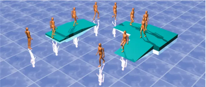
In this paper, we present a physics-based controller for animating three-dimensional biped characters that can react to dynamic environments in real time (Fig. 1). Our frame-work employs a balance motion filter that adjusts the desired motion trajectory in an online manner. Our biped balancing strategy is based on an inverted pendulum model (IPM) simplified from a full-body character model. The IPM simplification allows the balance motion filter to produce physically plausible and balanced motion trajectories for controllers to track. The dynamics of the IPM is so simple that the balance strategy can be determined in real time either by solving a closed form (on a flat ground) or through numerical root finding of a simple algebraic equation (on a slope). We adopted a velocity-driven tracking method to track the target trajectory generated by the balance motion filter. The velocity-driven tracking is formulated as a linear complimentary problem (LCP) to compute torques at joints that generate the desired joint velocities. The functionality of the velocity-driven tracking is similar to that of PD servos, but it does not require tedious parameter tuning and allows a large time step for simulation. Our results show that the proposed method allows three-dimensional biped characters to maintain their balance and respond to external perturbation while being simulated in real time.
This paper provides the following novel insights and contributions to the biped walking problem. First, although the IPM has been seen repeatedly in biomechanics and robotics, it has received much less attention in computer animation. We introduced a new problem to the graphics community that the IPM must also follow a motion capture example and proposed a novel method to solve this problem. To the best of our knowledge, the proposed method is the first one that does not require additional computational efforts in dealing with different motion styles
and character inertia parameters, while other methods often need a certain amount of offline computational time. Second, our method allows the character to withstand stronger disturbances because the balance motion filter calculates the exact foot-placing spot in real time. In contrast, other approaches rely on offline precomputed optimization or control parameter tuning procedures, resulting in weaker abilities in responding to unexpected perturbations. Finally, although great simplification in body segments is adopted to allow fast computation of balanced motion, the proposed method of transformation between the whole body and IPM shows the effectiveness of our approach.
2
R
ELATEDW
ORKDesigning dynamic controllers for biped characters is a fundamental issue in computer graphics and robotics. Animations of robust running and hopping gaits have been developed by Raibert, Hodgins, and their colleagues [12], [13], [14], [5]. The controls of running speed, jumping height, and trunk orientation are the key components of their approach. Dynamic balance during running is achieved by properly placing the landing position of the swing leg. Yin et al. proposed a similar balancing strategy that produces dynamic walking of three-dimensional biped characters [6]. Although these approaches have been successfully applied to the control of walking and running robots and animated characters, designing each controller requires significant manual work for tuning control para-meters. Several researchers explored algorithms for auto-matically adapting existing dynamic controllers to new characters [15] and new environments [16], [17] through parameter optimization.
Physics-motivated objectives and constraints have been employed in an optimization-based motion synthesis frame-work [18], [19], [20], [1], [4]. The burden for maintaining biped balance has often been circumvented by specifying the root trajectory kinematically [3] or using designated standing controllers [21], [22]. These optimization-based approaches successfully reproduced stylistic human motion Fig. 1. Real-time physics-based 3D character animation generated by our framework.
in animated characters and allowed motion capture data to be transformed to meet user-specified constraints.
Creating dynamic controllers that faithfully reproduce an integrated repertoire of human motor skills is a fundamental goal of physically based character animation. Yin et al. [6] mimicked captured motion styles by mixing local-and-world coordinate tracking with feedback error learning to achieve low-gain feedback and less motion oscillation. Sok et al. [7] addressed this goal by acquiring a collection of motion capture data, transforming each motion data into a physi-cally plausible form, and then learning integrated controllers automatically from the transformed training data. da Silva et al. [11] proposed an optimization-based method to generate interactive simulation of human locomotion. They adopted a three-link model with linearly approximated dynamics to form a balance objective. Optimal state feedback for the balance objective and style-following goal is computed to produce interactive animation.
The key idea of our approach is to utilize the inverted pendulum model which has been proposed in the robotics and biomechanics literature [23], [24], [25], [26], [27]. This simple model has been used to investigate the energy consumption [28], to develop continuous feedback control (based on the angular position and velocity of the inverted pendulum) in bipedal walking [23], and to track walking motion [29] in videos. Velocity-based stability margins for bipedal walking developed from the IPM was proposed and the capability of push recovery was tested [30]. A similar inverted multipendulum approach was presented for upright balance control of planar bipeds [31].
The IPM was rarely employed in animation literature. It has been used in animating turning motions in skiing and bicycling [32] and in standing balance control [33]. A notable usage of the IPM for walking was proposed by Bruderlin and Calvert [34] with inverted double pendulums and up to three essential motion pattern parameters specified by animators. The forces/torques satisfying the step constraints were approximated to solve a boundary value problem. Komura et al. [35] used a variant of the inverted pendulum model to compensate for angular momentum induced by external perturbations while walking. Unlike previous uses of the IPM, we employ the IPM for maintaining balance for dynamic biped walking without any artificial force or kinematic specification of the root trajectory. The simple dynamics of the IPM allows us to determine the precise behavior of the biped characters against large disturbances. Therefore, our full-body human-like characters can be dynamically simulated in real time and maintain their balance even for large external perturbation forces.
3
B
ACKGROUND: I
NVERTEDP
ENDULUMD
YNAMICS Our approach adopts an IPM to modify the target motion for motion tracking in real time. The modification can be considered as a physics-based motion editing process in which the input motion is modified to fulfill the physical balance requirements in a dynamic environment. As the inverted pendulum model is a key component of our approach, we first review the dynamics of an IPM in this section.3.1 Inverted Pendulum Model
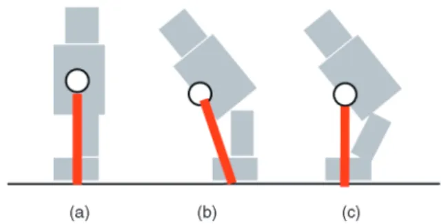
When a human body is supported by a single leg, the dynamical model can be simplified as an inverted pendu-lum as shown in Fig. 2. The inverted pendupendu-lum model consists of a point mass located at the center of mass (COM) of the full human body and an imaginary massless segment connecting the point mass to a ground contact point (center of pressure, COP). This simplification assumes that the ground friction is large enough to prevent slip and the ground reaction force acts on one point within the contact area of the stance foot.
The IPM simplification, which avoids complex kine-matics and dynamics calculations in the original multi-segment human skeleton, is a more intuitive and flexible way to control the balance of a character since the same model can be used for different motion styles (e.g., limped gait) or even different mass distribution (e.g., carrying weights). For example, Fig. 2a is the normal standing posture and the red line represents the inverted pendulum. If the body leans forward, the COM also moves subsequently as shown in Fig. 2b and the pendulum is unbalanced. The controller then adjusts the lower body posture and reposi-tions the COM to be above the stance foot. In this way, balance of the inverted pendulum is achieved as shown in Fig. 2c. Thus, the same balance control mechanism can work for different kinds of motions with little preprocessing.
3.2 Dynamics in the Single Stance Phase
The dynamical equation of the IPM can be easily derived using the law of energy conservation. The angular move-ment of the stance leg shown in Fig. 3a is thus described as the following equation:
1 2I! 2 sþ Z e s ðÞd¼1 2I! 2 e; ð1Þ
where !s and !e are the starting and ending angular
velocity of the inverted pendulum, respectively. ðÞ ¼ mgrsin is the torque due to the gravitational force mg applied from the initial angle s to the ending angle e, whereris the pendulum length. Computing the integral in (1), we can obtain 1 2I! 2 smgrðcosecossÞ ¼ 1 2I de dt 2 ; ð2Þ
Fig. 2. Inverted pendulum model of a human body: the circle represents the COM position and the red line is the pendulum. The pendulum is virtually connected to the ground with an unactuated joint. (a) Normal standing posture. (b) The body is unbalanced if the upper body’s orientation changes. (c) After posture adjustment, the balanced position of the inverted pendulum is achieved as in (a).
which is a nonlinear differential equation of eðtÞ. This equation is used to compute the trajectory of the COM and determine the landing position of the swing leg based on the constraints extracted from motion data.
3.3 Velocity Changes at the Double Stance Phase
Once the swing leg hits the ground, the single stance phase ends and the biped walking enters the double stance phase.
As the IPM is only valid for the single-stance phase, we simulate the double-stance phase by letting the simulated character simply follow the motion capture data. The roles of swing leg and stance leg exchange immediately after the double-stance phase ends. Fig. 3b depicts the IPM at the double stance phase. The velocity of the COM before and after foot strike is related by
V2¼V1cos; ð3Þ
where V1 and V2 are the velocity of the COM before and
after the swing leg strikes the ground, respectively, andis the angle between two legs. Note that when the swing leg hits the ground, the COM velocity along the axial direction vanishes due to the ground reaction force and only the tangential velocity component is left. Equation (3) also explains a finding from biomechanical investigations [28] that biped walking inevitably costs energy. The energy lost,
E, is E¼m 2V 2 1 m 2V 2 2 ¼ m 2ðV1sinÞ 2 ; ð4Þ
which is related to(or equivalently the step length). When the swing leg and stance leg exchange their roles, positive work must be done to maintain the same forward speed (provided that angle between the two legs is not zero). In real human motion, energy can be injected into the system by muscular work done by extending the stance leg and effectively pushing the ground. In the IPM motion, the lost energy is compensated by exerting appropriate joint torques to properly adjust the stance and swing leg so that the desired COM speed is achieved.
The most significant property of the double stance phase is that the ground reaction force along the swing leg can be exploited to eliminate the impact of external forces on the COM. Therefore, the balance motion filter can adjust the landing position of the swing leg and the length of the stance leg in order to produce positive work to keep walking and maintain balance. We will explain how the balance motion filter functions in Section 4.
4
O
URA
PPROACHFig. 4 shows an overview of our approach, which consists of the mapping between a full-body posture to a simplified IPM, balance motion filter, tracking control, and dynamics simulation. The function of each component is summarized as follows.
Fig. 3. (a) Single stance: The dynamics of the stance leg due to the gravity applied between two angular positionssandeis governed by
the law of energy conservation.!sand!e corresponds to the instant
angular velocity atsande, respectively. (b) Double stance: Velocity
changes at the double stance phase. Before the swing leg strikes the ground, the COM velocity isV1. After the swing leg lands, the stance leg immediately leaves the ground and the COM velocity becomesV2.V1 andV2are perpendicular to the stance and swing leg, respectively.
Full body to IPM.Given input motion data, our system first computes the COM of the full body. The IPM is then formed by connecting the COM and the COP of the feet.
Balance motion filter.Using the IPM, the balance motion filter computes the COM trajectory and landing position of the leg so that a desired COM trajectory computed from motion data is achieved. The impact of any external force is eliminated by adjusting the landing position.
IPM to full body.A full-body posture is reconstructed based on the COM position and the leg landing position of the IPM (output of motion balance filter) and the upper body posture from the input motion data.
Tracking control. We adopt a velocity-driven method which computes the desired angular velocity of each joint based on the tracking error between the desired joint angle and simulated joint angle. The error-velocity mapping function mimics the ease-in/ease-out (slow-start/slow-stop) control strategy used by humans.
Dynamics simulation. The desired joint angular velo-cities computed by the tracking control are treated as equality constraints in dynamics simulation. Taking contact constraints and external forces into account, we formulate our constrained dynamics simulation problem as a Linear Complementarity Problem (LCP) and use the Open Dynamics Engine (ODE) to solve the LCP to obtain the joint torques. Finally, ODE performs dynamics simulation to generate the output motion.
4.1 Posture Mapping between Full Body and IPM
We need to convert a full-body posture to/from an IPM posture since the balance motion filter operates in the IPM space while both the motion data and dynamics simulation are represented in a full-body posture space.
Full body to IPM.At preprocessing, we first identify the swing leg and stance leg in the motion data by examining
whether the trajectory of a foot touches the ground and then determine the start of a gait cycle by detecting foot-strike moments. We then convert the full-body postures to IPM postures by calculating the COM position, total body moment of inertia about the COM, and the COP position of the stance leg. The mass, COM, and the moment of inertia of each body segment of our character model are based on the data in [36]. With these values, the COM of the total body at any posture can be calculated. Since motion data do not provide the information of COP position, the COP is assumed to be at the center of the metatarsal phalangeal joint. Thus, the IPM postures are specified by the COM of the total body, the pendulum length of the IPM (the distance between COP and COM), and the orientation of the leg. The average speed of the COM is used as the target speed of the IPM.
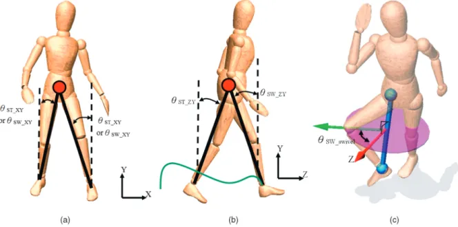
The orientation of the legs is computed as shown in Fig. 5. We define a local coordinate attached at the COM of the full-body character, where theY-axis is always aligned with the up direction of the global coordinate. In this way, theXY plane andY Zplane are defined as the frontal plane and sagittal plane, respectively. The orientation of the legs of the IPM are then represented by the angles between the Y-axis and the legs of the IPM projected on the frontal (XY) and sagittal (ZY) plane:SW XY; ST XY; SW ZY, andST ZY. Here SW stands for “swing leg,” and ST stands for “stance leg.” In addition, we compute the swivel angles of the knee jointsSW swivel andST swivel. These two angles are used to reconstruct the position of the knee joints when mapping an IPM posture to a full-body posture.
IPM to full body. After the balance motion filter computes a balanced motion of the IPM, we need to convert it back to a multisegment full-body motion. We first reconstruct the hip and knee angles using the information of COM, COP, andSW swivel(orST swivel). For each leg, we Fig. 5. Mapping between the full body and the IPM. The black lines connecting the COM and COP of the character are the legs of the IPM. We define a local coordinate attached at the COM of the full-body character, where the Y-axis is always aligned with the upward direction of the global coordinate andZ-axis points toward the forward direction. To represent the orientation of the legs of the IPM, we project the IPM’s legs on the (a) frontal and (b) sagittal plane, respectively. The angles between the projected line and the Y-axis denote the orientation of the legs of the IPM. In addition, the swivel angle defined in (c) is kept so that the knee position can be reconstructed when mapping an IPM posture to a full-body posture.
need to compute four angles, three DOF for the hip, and one DOF for the knee, to bring the end-effecter of the foot to the correct COP position. This is a typical inverse kinematics (IK) problem, which can be solved analytically using an approach similar to Lee and Shin’s method [37]. We assume the toe part is flat while the ankle angle generally follows the motion capture data. When the stance foot in the motion captured data is flat on the ground and the current COM horizontal velocity differs from the target value, we adjust the stance ankle angle in the desired motion trajectory when mapping an IPM posture to a full-body posture. For example, when the COM moves faster than the desired speed, the ankle angle is adjusted such that the stance leg contacts the ground with the toes. Otherwise, the heel contacts the ground.
In addition, the swing leg trajectory is generated accord-ing to the motion capture data. Since the step length calculated by the balance motion filter may be different from the motion capture data, the path of the foot is rescaled. The new path usually has similar shape as the motion capture data with the same height but the step length becomes identical to that calculated by the balance motion filter. The landing time is determined by the calculated swing leg trajectory; however, it can also be specified by users to explicitly control the landing time of the swing leg. The upper body can either track the motion capture data or be specified by the animator. Motion tracking may not be achieved perfectly since the velocity constraints may be violated if any computed joint torque exceeds the preset torque limit. The proposed method focuses on the lower body rather than the upper body because the formal is considered more crucial to balance motions.
4.2 Balance Motion Filter
A key component in our framework is the balance motion filter, which computes balanced motion trajectories based on the IPM dynamics and the IPM motion converted from the input motion data. The design of the balance motion filter is motivated by the need for instantly predicting a proper landing of the swing leg to maintain balanced motion using simple equations. Two major tasks of the balance motion filter are: 1) computing the trajectory of the COM and 2) adjusting the leg landing position to maintain the balance of the IPM and reproduce the motion characteristics in the input motion data. The computed COM trajectory and leg landing position are then used to generate the desired joint angles of hips, knees, ankles, and toes in full-body dynamics simulation. As the computational cost of the IPM dynamics is low, our balance motion filtering is executed at all time instants so that unexpected disturbances in a dynamic environment can be handled in real time.
The position and velocity of the COM in the single stance phase,ST andVST, can be easily computed using (1). When the swing leg hits the ground, the ground reaction force along the swing leg is utilized to cancel out the impact of external force applied to the animated character. At the double stance phase, the position and velocity of the COM is obtained from the motion capture data to be tracked.
The computation of the landing position of the swing leg is illustrated in Fig. 6. The landing position is determined by the unknown parameterSW1. Suppose the desired position
and velocity of COM at specified time are given, i.e.,SW2
andVSW2are known parameters extracted from the motion
capture data. The only unknown parameter SW1 can be
computed by combining (1) and (2):
1 2I! 2 SW1mgrðcosSW2cosSW1Þ ¼ 1 2I! 2 SW2; ð5Þ
where the angular velocities !SW1 and !SW2 are obtained
from the linear velocities of the COM, !SW1¼ 1 rVSW1¼ 1 rVSTcosðSW1þSTÞ; ð6Þ !SW2¼ 1 rVSW2: ð7Þ
VST and VSW1 are the COM velocities immediately before
and after the swing leg strikes the ground, respectively. Equation (5) is solved numerically using the fourth-order Runge-Kutta method since there is no closed-form solution for SW1. Although the numerical solution of the contact
angleSW1may not be precise, this numerical error does not
affect the balance control of the character since corrections are made in subsequent time steps.
The IPM length r is actually not constant because the movements of body segments affect the COM position, and consequently COM to COP distance. Likewise,rneeds to be changed on a slope. In either case,ris repeatedly computed at each time step. The length of the swing leg r can be calculated from the height of COMLyusing
r¼ Lysinð
2ST GÞ
cosSTsinð2SW1þGÞ
; ð8Þ
whereGis the slope angle of the ground.
Equation (5) describes the dynamics in the 2D case. In a 3D environment, the calculation is divided into a frontal and a sagittal plane. Thus,SW2becomesSW XY orSW ZY Fig. 6. The ground reaction force at the double stance phase is exploited to eliminate the impact of external forces exerting on the IPM in the single stance phase. The direction of ground reaction force is determined by the landing position of the swing leg. Hence, an appropriateSW1is computed to achieve a desired COM velocityVSW2 when the COM velocityVST at the single stance phase is affected by
external forces. Subscript 1 and 2 means before and after the swing leg striking ground, respectively.
in 3D and similarly for other variables. It is likely that the ending states of the COM are not achieved simultaneously on the two planes. If this discrepancy exists, the shorter time duration is used.
We can also easily generate the turning motion of the character by adjusting the foot landing position and the COM orientation. This can be achieved by simply rotating the stance leg. In particular, the facing direction of the character is determined by SW swivel. Once the turning motion of IPM is computed, the turning motion of the full body can be obtained by mapping the IPM posture to full-body posture.
4.3 Tracking Control and Dynamics Simulation
The dynamics simulation of an animated character in our system is treated as a constrained multi-rigid-body dynamics problem. We represent the system dynamics in the maximal coordinate and enforce the articulation constraint, which keeps the character’s bones connected by joints during motion. The character is controlled by a velocity-driven tracking controller, which computes the desired joint velocities based on the tracking error. As the desired joint velocities are specified in the general coordi-nate, they are converted to the maximal coordicoordi-nate, that is, linear and angular velocities at the COM of each bone in the global coordinate. The converted linear and angular velocities are then treated as the velocity constraints for each bone. By treating controlling inputs as constraints, we can solve both the dynamics simulation and the character control problem in a unified formulation.
The Lagrange multiplier formulation is used to solve our
constrained multi-rigid-body dynamics problem. Let Vi
andMidenote the velocity and mass property matrix of the ith body, respectively. The accelerationV_iof theith body in response to the forceFi is
MiV_i¼Fi: ð9Þ
Note thatViincludes both linear and angular components
of the velocity, and Fi may represent both forces and
toques. When dealing with a system of many bodies (or bones in a skeletal system), we use the vectorsF;V, andM
to indicate vectors and matrices that contain the informa-tion for the entire system. For a system withnbodies andm constraints, including all articulation and joint velocity constraints, the constraint equation for the entire system is represented as JVþC¼ J11 J12 J1n J21 J22 J2n .. . . . . .. . Jm1 Jm2 Jmn 0 B B B @ 1 C C C A V1 V2 .. . Vn 0 B B B @ 1 C C C AþC¼0; ð10Þ
where Jki is the kth constraint Jacobian matrix enforced
on the ith body. Taking the derivative on the velocity
constraint equation, we can obtain an acceleration constraint equation J _VþK¼0.
The total force exerting on the system is the sum of the external forceFextand the constraint forces JT. Combin-ing the Newton-Euler equations,
F¼FextþJT¼M _V; ð11Þ
with the constraint equation J _VþK¼0, we obtain the following Lagrange multiplier equation,
M JT J 0 _ V ¼ F ext K : ð12Þ
To handle contact forces and joint torque limits, which are usually modeled as inequality constraints, we need to include inequality constraint equations a¼J _VþK0, where a is an auxiliary variable. Let Je and Jc be the Jacobian of the equality and inequality constraints, respec-tively, we can modify (12) as
0 0 a 0 B @ 1 C A M JeT JcT Je 0 0 Jc 0 0 0 B @ 1 C A _ V e c 0 B @ 1 C A¼ Fext Ke Kc 0 B @ 1 C A; a0;c0;aTc¼0: ð13Þ
Equation (13) can be converted into a Linear Complemen-tarity Problem (LCP) [38]. The contact model proposed by Baraff [39] is used to compute the ground contact forces since the model is formulated as an LCP as well. The LCP formulation allows us to compute the torques and forces for tracking control, forward dynamics, and contact constraints under the same unified framework. This reduces the burden for tackling these three subproblems separately and provides a more stable and efficient numerical simulation system.
We use an LCP solver in ODE to solve our problem. Under this formulation, the simulated character is con-trolled by specifying the joint velocity constraints at each time step, which we called the velocity-driven tracking control method. The LCP solver provided by ODE computes torques that can drive the character’s joints to reach the desired velocities within one or several time steps. In this way, tracking control is simplified as specifying the desired joint velocities at each time step. More importantly, our tracking control approach ameliorates the problem of manual tuning or computationally expensive optimization that are commonly used for setting appropriate gains in PD-control-based approaches. Note that we do not specify any other constraints in addition to joint velocity and ground contact constraints. Therefore, the character’s motion is only driven by joint torques rather than any actuator at the root. Fig. 7 illustrates the idea of our velocity-driven control method. To specify the desired joint angular velocities, we design an error-velocity curve inspired by the bell-shaped curve in biomechanics [40]. According to this curve, the controller is designed such that the desired joint angular velocity increases at larger tracking errors, and declines at smaller errors. In particular, when the tracking error is large or small, the adjustment (variation) of angular velocity is small. This implies that at the beginning of tracking (when the tracking error is usually larger), the controller steadily outputs large torques to accelerate the joint rotation while when the desired value is approaching, the controller reduces torque gradually. On the other hand, when the tracking error is in the middle range, the slope of error-velocity curve is large. This implies that the controller is more sensitive at the normal error range.
Thus, from the tracking error between the current joint angle and the desired joint angle, the desired angular velocity of a joint can be acquired by the error-velocity curve in Fig. 7. After the angular velocities are assigned, ODE solves the linear complementarity problem to obtain the required joint torques for achieving the desired angular velocities and consequently the desired posture. As the muscle strength for each joint is different,Frad2velðerrÞis multiplied by a constant
cito model this variation, i.e., the desired angular velocity of the ith joint is !i¼ciFrad2velðerrÞ. Largerci value means that the joint to be controlled can achieve the target position faster. In addition, each joint has its own limit on the torque that it can generate. These joint torque limits are enforced as inequality constraints in the LCP. Since the error-velocity relation and the maximal joint torques that the human model can produce are both predefined values, desired motions can be achieved without tedious control parameter adjustments, and the same set of control parameters can be used for different types of motions.
Our velocity-driven control approach is actually similar to a PD controller in which the applied forces/torques are obtained according to the differences in the current and target positions/velocities. We further simplify the
con-troller by using only the velocity information because of the bell-shaped curve [40] in the biomechanics literature. The comparison between tracking with PD and velocity-driven controllers in our pilot experiments showed the validity of this method. We also experimented with other error-velocity curves, which allow the desired joint angular velocity to increase with the tracking error, e.g., a linear relation. Although these curves can also generate acceptable results, the relation in Fig. 7 is adopted because it produces better results.
5
R
ESULTSWe used the proposed approach to generate 3D character animations that respond to dynamical environments in real time. Three sets of experiments are performed: imitating motion capture data (Section 5.1), motion styles and transitions (Section 5.2), robustness (Section 5.3). The skeleton model (Table 1) used in our experiments is modified from the skeleton in CMU’s Motion Capture Database. For better balance control, we add one more degree of freedom (DOF) at the ankle joint (3 DOF). Thus, the skeleton has 30 joints and 58 DOF in total. Body segment mass and moment inertia parameters are from [36] with the total mass of 81.4 kg. The Coulomb friction model is adopted as the ground contact model and the friction coefficient of the ground is 1. For all the experiments, motions are simulated using a time step of 0.02 seconds with the resulting frame rate of 25 frames per second. On an Intel E8400 PC, the computational time of the balance motion filter and the tracking control with dynamics simulation are 5.10 ms and 8.45 ms, respec-tively. Thus, the ratio of simulation time versus real time is 13:55 ms= 20 ms¼0:68.
5.1 Balanced Walking with Motion Capture Imitation
Our balance motion filter with velocity-driven tracking control successfully simulates biped walking without Fig. 7. Error-velocity curve Frad2velðerrÞ, where err is the difference
between the desired joint angle and current joint angle.
TABLE 1
falling while mimicking motion capture data in a 3D environment (see our accompanying video which can be found on the Computer Society Digital Library at http:// doi.ieeecomputersociety.org/10.1109/TVCG.2009.761).
Spe-cifically, the lower body motion is governed by the IPM with balance motion filter which ensures dynamic balance during walking, while the upper body imitates the motion data. One can observe that our simulated motions are close to the motion captured data (see the accom-panying video which can be found on the Computer Society Digital Library at http://doi.ieeecomputersociety. org/10.1109/TVCG.2009.76). Although the lower body joint angles are determined by the IPM leg length without tracking motion capture data, these angles are also close to the motion capture data.
5.2 Generating Physically Correct Motion Styles and Motion Transition
Our method can be used to modify motion styles, where physically correct balanced motion are generated according to the posture or environment constraints either offline specified at key frames or online given by a user. The modification on motion is very flexible since all variables that are not directly responsible for balance can be adjusted freely while a balanced motion can still be maintained. For example, we can specify the hip and knee angles to let the swing foot clear a certain height to imitate the motion when passing over an obstacle. We can also tilt the trunk forward to simulate the crouched gait of the elderly, or tilt the trunk sideway to mimic walking with carrying a heavy load in one hand. Because the position of the effective mass of the IPM (the COM of the multisegment model) is calculated at each time step, any
variation in the upper body configuration is taken into account when placing the swing leg of the IPM. Therefore, walking patterns in our simulations demonstrate seemly natural and physically correct adaption to different torso orientations specified by a user (Figs. 8 and 9, and the accompanying video which can be found on the Computer Society Digital Library at http://doi.ieeecomputersociety. org/10.1109/TVCG.2009.76). Furthermore, since our motion balance filter only cares about proper landing of the swing leg, its moving path can be adjusted arbitrarily. Thus, the landing spot can be controlled by varying the six angle parameters in Section 4.2. This can be used to generate turning motion (see the accompany video which can be found on the Computer Society Digital Library at http://doi. ieeecomputersociety.org/10.1109/TVCG.2009.76).
Note that the required user intervention in these results is very simple. We basically let the character follow the captured normal walking motion. We then set the desired angles for the joints to be modified at two or three key frames and temporarily lower theci values at these joints between these key frames. A smooth motion can be produced easily; thanks to the balance motion filter and dynamics simulation. No extra editing was done and the motion was generated in real time.
In our approach, transition between different types of motions can be performed easily without the need for motion blending. For example, by changing the desired COM moving velocity from positive to negative, our character can smoothly change the walking direction from forward to backward. A character’s moving speed can also be controlled easily by changing the target speed VSW2 in
the proposed balance motion filter. This kind of minimal control parameter adjustment is more user friendly com-pared to other approaches in which transitions need to be
1. Our accompanying video is also available at http://graphics.csie. ncku.edu.tw/IPM/.
Fig. 8. Character twisting its upper body to pass through a narrow walkway. In this example, the input motion capture data is walking straight forward and our method can be used to modify the motion style by simply adjusting the orientation of the torso.
found manually [6], [11] or precomputed with much more efforts [41], [42], [43].
5.3 Robustness
We demonstrated the robustness of our approach by testing it under uneven terrains, unexpected external forces and variations of model parameters.
Uneven terrains. The most distinctive feature of our method is its ability to react to unexpected disturbances in real time. We demonstrate this by letting the animated character walk on uneven terrains. We adjust the IPM leg length, which corresponds to leg flexion or extension in the multisegment model, when nonplanar ground surface is detected. Our approach allows the character to successfully walk up and down on slopes of up to 15 degrees. This result shows that our approach is more robust than previous methods [6], [11], in which the character can walk on slopes of up to 5 or 6 degrees.
Unexpected external forces. In addition, we also tested the robustness of our controllers by exposing the character to unexpected external pushing forces (or impulses). The goal is to maintain standing or walking balance by taking several steps after a push or pull. Once an external force is applied, the COM velocity is first calculated, and then the IPM is utilized to estimate the remaining COM velocity after each swing leg placement. We tested the balance recovery capability of our controllers by pushing the character with different impulse magnitudes and from different horizontal directions (see Fig. 10 and accompanying video which can
be found on the Computer Society Digital Library at http:// doi.ieeecomputersociety.org/10.1109/TVCG.2009.76). The maximal applied force lasting 0.4 s in eight evenly sampled directions are (unit: Newton (N)): (0 N,486.02 N), (354.75 N, 321.30 N), (456.24 N, 0 N), (266.06 N, 365:90 N), (0 N,
457:72 N), (296:91 N, 341:59 N), (469:68 N, 0 N),
(270:78 N, 380.75 N). Comparing with the maximal
impulse (340 N in 0.4 sec) that the character can withstand in [6], our method endures larger disturbance without adjusting any control parameters.
Model parameter variations. Because any kind of human body can be modeled using an IPM, our controllers can successfully simulate the motion of bodies with different sizes. In the accompanying video which can be found on the Computer Society Digital Library at http:// doi.ieeecomputersociety.org/10.1109/TVCG.2009.76, we show that characters with the original leg length, and twice or half of it, can be controlled using the same set of control parameters without any difficulty. In contrast, similar robustness was tested by only a 10 percent increase in the leg (femur) length in [6]. In addition, our method uses the same set of control parameters, while manual tuning of feedback gains for different characters is sometimes necessary in [6].
5.4 Discussion
From our experimental results, one can find that the most significant advantage of our work over prior work is that our method requires no preprocessing and allows the Fig. 9. Snapshots of a character walking while stooping under a barrier. This example is generated by bending the back and lowering the COM of the character in a motion capture data of normal walking. Note that the squatting motion of the lower body is generated automatically by our method.
animated character to react to dynamic environmental changes in real time. More importantly, although the control parameters can be tuned to yield different com-pliance in response to perturbations, the character can still withstand large external disturbances and achieve desired joint angles and motion styles instantly without parameter tuning. On the contrary, although prior feedback controllers can track a desired motion well, they need additional efforts to generate different motion styles subject to environmental changes in real time. For example, parameter adjustments are still inevitable in recent methods [6], [44], [7]. These methods can run in real time only after task- or model-specific parameters are computed offline, which usually cost from 2 to 15 minutes for each simulation.
In particular, to judge the performance of our approach, we compare our results with SIMBICON’s in the accom-pany video which can be found on the Computer Society Digital Library at http://doi.ieeecomputersociety.org/ 10.1109/TVCG.2009.76. One can observe that our approach can generate physically correct animation with comparable motion quality to those generated by SIMBICON. Never-theless, our approach is more robust in terms of balance control and is more efficient in terms of controller design. These advantages are gained from two major differences
between our approach and SIMBICON. First, from the
aspect of control strategy, we adopt a totally different balance control mechanism. SIMBICON achieves balance through balance feedback control where the strategy is to adjust the desired target value for tracking based on the COM position relative to the stance ankle and COM velocity. The COM position is approximated by the midpoint of the hips. They do not actually analyze the dynamics of the character for maintaining balance and need to tune the balance feedback gains to achieve balance. In our approach, we adopt the inverted pendulum dynamics to online compute the balance state of the character. Therefore, dynamic balance of the computed motion trajectory is automatically guaranteed without the need of an additional feedback loop and control parameter tuning.Second, from the aspect of controller design, SIMBICON utilizes a finite state machine to choose a set of controllers for each state. Hence, controllers need to be redesigned for different motions and for characters of different sizes. In general, our approach slightly trade the motion quality to gain the robustness, efficiency, and flexibility. These properties make our approach very attractive for generating physically correct responsive animation in real-time applications.2
There are still some limitations in our approach. Although our approach can generally follow the motion capture data fairly well, minor tracking errors are still unavoidable. Usually the errors can be compensated by tracking joint angles in the next step. However, the errors may also accumulate after tracking a number of steps, causing noticeable differences between the captured and
simulated motion. Moreover, reconciliation for the occa-sionally conflicting objectives of balance maintenance and motion tracking is inevitable, which also leads to unmatched captured and animated motion data. In addition, physically correct motions may not look natural. For example, during a sharp left turn it is necessary to create a force which pushes the body to the left. The character may use the left foot to land on the right side of body rather than using the right foot. Adding more constraints to guarantee natural-looking motions will be our future work. Nevertheless, our method provides a way to combine tracking the whole body COM and joint angles, which can be considered as a more effective version of [21]. Moreover, producing perfectly natural-looking motion still remains a challenge. Jerky motion in the video (the character is walking while crouching under a barrier) was generated because the target trajectory was arbitrarily modified to bend forward. Despite the large change of the target trajectory, our method still allows steady and balanced walking with a bent upper body.
Currently, our approach can only allow the upper body to follow some specified target motions and respond passively to external perturbations through altered COM position which influences balance control. The ability for the upper body to actively respond to perturbations, e.g., by moving the arms for balance recovery, is not included in our model. Developing new methods or modifying existing techniques [45] will be our future work. We can assume some plausible upper body reactions based on the position and magnitude of the applied force. In every time step the balance motion filter can take into account COM displacements due to upper body motions, and predict the desired foot landing position for maintaining a gait cycle. Thus, when the upper body is modified kinematically, the lower body motion is then determined in synchronization with the upper body.
6
C
ONCLUSIONWe present a physics-based approach to animate a 3D biped character that can react to dynamical environments while tracking stylistic motions in real time. The IPM-based balance motion filter provides an intuitive and efficient way to adapt the motion trajectories to dynamical environ-ments. This adaption reduces the difficulty of controlling a simulated character since the desired motion trajectories are physically plausible and we are able to use a velocity-driven method to track desired motion trajectories. The velocity-driven tracking control avoids the tedious process of tuning control parameters. Using the same set of control para-meters, our approach can not only reproduce stylistic variations of human motion but also allow the target trajectory to be varied in a physically plausible manner. Our experiments also show that the proposed approach is robust to environmental changes (stairs, uphill/downhill up to 15 degrees), external distances (700 N force for 0.2 seconds), and model parameter variations.
Although our approach demonstrates promising results of applying physics-based simulation to character anima-tion, the motion styles of the simulated character are still limited by the motion database. To increase the richness of the motion styles, we need to incorporate more high-level motor control strategies used in human motion. Some of these high-level motor control strategies can be transferred
2. In our personal communication with the first author of SIMBICON, KangKang Yin, she also agrees that our approach may slightly trade the motion quality for the robustness, efficiency, and flexibility. In particular, our approach does not require additional efforts to design a finite state machine or tune control parameters for different types of motions and/or for motion transitions. Also, the same set of control parameters can be used for characters of different sizes.
onto an IPM. We would like to investigate this possibility to produce more motion styles in our future work. Besides, generating the interactive motion between two or among more characters is also one of our future goals.
A
CKNOWLEDGMENTSThe authors would like to thank anonymous reviewers for their helpful comments to improve this paper. We are also grateful to KangKang Yin and Michiel van de Panne to help us to perform experimental study with their work [6]. This work is supported in part by the Landmark Program of the NCKU Top University Project (Contract B0008), and the National Science Council (Grants 97-2628-E-006-125-MY3, NSC-96-2628-E-006-200-MY3, NSC-96-2221-E-006-244-MY2, and NSC-96-2221-E-009-152-MY3), Taiwan, Republic of China. For correspondence, please contact Professor Tong-Yee Lee at [email protected]
R
EFERENCES[1] A.C. Fang and N.S. Pollard, “Efficient Synthesis of Physically Valid Human Motion,” ACM Trans. Graphics, vol. 26, no. 3, pp. 417-426, 2003.
[2] A. Safonova, J.K. Hodgins, and N.S. Pollard, “Synthesizing Physically Realistic Human Motion in Low-Dimensional, Beha-vior-Specific Spaces,”ACM Trans. Graphics,vol. 23, no. 3, pp. 514-521, 2004.
[3] C.K. Liu, A. Hertzmann, and Z. Popovic, “Learning Physics-Based Motion Style with Nonlinear Inverse Optimization,”ACM Trans. Graphics,vol. 24, no. 3, pp. 1071-1081, 2005.
[4] A. Sulejmanpasic and J. Popovic, “Adaptation of Performed Ballistic Motion,”ACM Trans. Graphics,vol. 24, no. 1, pp. 165-179, 2005.
[5] J.K. Hodgins, W.L. Wooten, D.C. Brogan, and J.F. O’Brien, “Animating Human Athletics,” Proc. ACM SIGGRAPH ’95,
pp. 71-78, 1995.
[6] K. Yin, K. Loken, and M. van de Panne, “Simbicon: Simple Biped Locomotion Control,”Proc. ACM SIGGRAPH ’07,p. 105, 2007.
[7] K.W. Sok, M. Kim, and J. Lee, “Simulating Biped Behaviors from Human Motion Data,”Proc. ACM SIGGRAPH ’07,p. 107, 2007.
[8] J. Lee, J. Chai, P.S.A. Reitsma, J.K. Hodgins, and N.S. Pollard, “Interactive Control of Avatars Animated with Human Motion Data,”ACM Trans. Graphics,vol. 21, no. 3, pp. 491-500, 2002.
[9] L. Kovar, M. Gleicher, and F. Pighin, “Motion Graphs,” ACM Trans. Graphics,vol. 21, no. 3, pp. 473-482, 2002.
[10] Y. Li, T. Wang, and H.-Y. Shum, “Motion Texture: A Two-Level Statistical Model for Character Motion Synthesis,” ACM Trans. Graphics,vol. 21, no. 3, pp. 465-472, 2002.
[11] M. da Silva, Y. Abe, and J. Popovic, “Interactive Simulation of Stylized Human Locomotion,”ACM Trans. Graphics,vol. 27, no. 3, pp. 82:1-82:10, 2008.
[12] M.H. Raibert,Legged Robots that Balance.Mass. Inst. of Technology, 1986.
[13] M.H. Raibert and J.K. Hodgins, “Animation of Dynamic Legged Locomotion,”Proc. ACM SIGGRAPH ’91,pp. 349-358, 1991.
[14] J.K. Hodgins, “Biped Gait Transitions,” Proc. IEEE Int’l Conf. Robotics and Automation,1991.
[15] J.K. Hodgins and N.S. Pollard, “Adapting Simulated Behaviors for New Characters,” Proc. ACM SIGGRAPH ’97,pp. 153-162, Aug. 1997.
[16] S. Coros, P. Beaudoin, K. Yin, and M. van de Panne, “Synthesis of Constrained Walking Skills,” ACM Trans. Graphics (Proc. ACM SIGGRAPH Asia), vol. 27, no. 6, 2008.
[17] K. Yin, S. Coros, P. Beaudoin, and M. van de Panne, “Continuation Methods for Adapting Simulated Skills,” ACM Trans. Graphics,
vol. 27, no. 3, 2008.
[18] A. Witkin and M. Kass, “Spacetime Constraints,” Proc. ACM SIGGRAPH ’88,pp. 159-168, 1988.
[19] M.F. Cohen, “Interactive Spacetime Control for Animation,”Proc. ACM SIGGRAPH ’92,pp. 293-302, 1992.
[20] Z. Popovic and A. Witkin, “Physically Based Motion Transforma-tion,”Proc. ACM SIGGRAPH ’99,pp. 11-20, Aug. 1999.
[21] V.B. Zordan and J.K. Hodgins, “Motion Capture-Driven Simula-tions that Hit and React,”Proc. Symp. Computer Animation (SCA),
pp. 89-96, 2002.
[22] Y. Abe, M. da Silva, and J. Popovic, “Multiobjective Control with Frictional Contacts,” Proc. Symp. Computer Animation (SCA),
pp. 249-258, 2007.
[23] H. Miura and I. Shimoyama, “Dynamic Walk of a Biped,”Int’l J. Robotics Research,vol. 3, no. 2, pp. 60-74, 1984.
[24] S. Kitamura, Y. Kurematsu, and M. Iwata, “Motion Generation of a Biped Locomotive Robot Using an Inverted Pendulum Model and Neural Networks,” Proc. IEEE Conf. Decision and Control,
vol. 6, pp. 3308-3312, 1990.
[25] S. Kajita, F. Kanehiro, K. Kaneko, K. Yokoi, and H. Hirukawa, “The 3d Linear Inverted Pendulum Mode: A Simple Modeling for a Bipedwalking Pattern Generation,”Proc. IEEE/RSJ Int’l Conf. Intelligent Robots and Systems,vol. 1, pp. 239-246, 2001.
[26] A.D. Kuo, “Stabilization of Lateral Motion in Passive Dynamic Walking,”Int’l J. Robotics Research,vol. 18, no. 9, pp. 917-930, 1999.
[27] M. Srinivasan and A. Ruina, “Computer Optimization of a Minimal Biped Model Discovers Walking and Running,”Nature,
vol. 439, no. 7072, pp. 72-75, Jan. 2006.
[28] A.D. Kuo, J.M. Donelan, and A. Ruina, “Energetic Consequences of Walking Like an Inverted Pendulum: Step-to-Step Transitions,”
Exercise and Sport Sciences Rev.,vol. 33, no. 2, pp. 88-97, 2005.
[29] M. Brubaker, D.J. Fleet, and A. Hertzmann, “Physics-Based Person Tracking Using Simplified Lower-Body Dynamics,”Proc. Compu-ter Vision and PatCompu-tern Recognition,pp. 1-8, 2007.
[30] J.E. Pratt and R. Tedrake, “Velocity-Based Stability Margins for Fast Bipedal Walking,” Proc. First Ruperto Carola Symp. Fast Motions in Biomechanics and Robotics: Optimization and Feedback Control,pp. 299-324, 2005.
[31] M. Abdallah and A. Goswami, “A Biomechanically Motivated Two-Phase Strategy for Biped Upright Balance Control,” Proc. IEEE Int’l Conf. Robotics and Automation,pp. 1996-2001, 2005.
[32] M. van de Panne, E. Fiume, and Z.G. Vranesic, “Physically-Based Modeling and Control of Turning,”Computer Vision, Graphics, and Image Processing: Graphical Models and Image Processing,vol. 55, no. 6, pp. 507-521, 1993.
[33] P. Faloutsos, M. van de Panne, and D. Terzopoulos, “Composable Controllers for Physics-Based Character Animation,”Proc. ACM SIGGRAPH ’01,pp. 251-260, 2001.
[34] A. Bruderlin and T.W. Calvert, “Goal-Directed, Dynamic Anima-tion of Human Walking,”Proc. ACM SIGGRAPH ’89,pp. 233-242, 1989.
[35] T. Komura, H. Leung, S. Kudoh, and J. Kuffner, “Animating Reactive Motions for Biped Locomotion,” Proc. Virtual Reality Software and Technology (VRST ’04),pp. 32-40, 2004.
[36] G. Harry, Anthropometry and Mass Distribution for Human Analogues. Volume I: Military Male Aviator. Defense Technical Information Center, Mar. 1988.
[37] J. Lee and S.Y. Shin, “A Hierarchical Approach to Interactive Motion Editing for Human-Like Figures,”Proc. ACM SIGGRAPH ’99,pp. 39-48, 1999.
[38] M. Cline and D. Pai, “Post-Stabilization for Rigid Body Simulation with Contact and Constraints,”Proc. IEEE Int’l Conf. Robotics and Automation,vol. 3, pp. 3744-3751, 2003.
[39] D. Baraff, “Fast Contact Force Computation for Nonpenetrating Rigid Bodies,”Proc. ACM SIGGRAPH ’94,pp. 23-34, 1994.
[40] T. Flash and N. Hogan, “The Coordination of Arm Move-ments: An Experimentally Confirmed Mathematical Model,”
J. Neuroscience, vol. 5, no. 7, pp. 1688-1703, 1985.
[41] J. Lee and K.H. Lee, “Precomputing Avatar Behavior from Human Motion Data,”Proc. Symp. Computer Animation (SCA),pp. 79-87, 2004.
[42] J. McCann and N. Pollard, “Responsive Characters from Motion Fragments,”ACM Trans. Graphics,vol. 26, no. 3, pp. 6:1-6:7, 2007.
[43] A. Treuille, Y. Lee, and Z. Popovic, “Near-Optimal Character Animation with Continuous Control,” ACM Trans. Graphics,
vol. 26, no. 3, pp. 7:1-7:7, 2007.
[44] M. da Silva, Y. Abe, and J. Popovic, “Simulation of Human Motion Data Using Short-Horizon Model-Predictive Control,”Computer Graphics Forum,vol. 27, no. 2, pp. 371-380, 2008.
[45] Y. Ye and C.K. Liu, “Animating Responsive Characters with Dynamic Constraints in Near-Unactuated Coordinates,” ACM Trans. Graphics,vol. 27, no. 5, pp. 1-5, 2008.
Yao-Yang Tsaireceived the master’s degree in computer science/engineering from the National Cheng-Kung University, Taiwan, 2008. He is currently working at Human Computer Interac-tion Technology Center of Industrial Technology Research Institute South. His research interests include computer graphics, physics-based simu-lation, and human animation. He is also asso-ciated with the Computer Graphics Group, Visual System Laboratory, National Cheng-Kung University (http://graphics.csie.ncku.edu.tw/).
Wen-Chieh Lin received the BS and MS degrees in control engineering from the National Chiao-Tung University, Hsinchu, Taiwan, in 1994 and 1996, respectively, and the PhD degree in robotics from Carnegie Mellon Uni-versity, Pittsburgh, in 2005. Since 2006, he has been with the Department of Computer Science and the Institute of Multimedia Engineering, National Chiao-Tung University, as an assistant professor. His current research interests include computer graphics, computer animation, and computer vision. He is a member of the IEEE and the ACM.
Kuangyou B. Chengreceived the BS degree in physics from the National Taiwan University, Taiwan in 1995, and the MS and MSE degrees in kinesiology and mechanical engineering, respectively, from the University of Michigan, Ann Arbor, in 1999. He completed the PhD degree in the area of control systems and biomechanics at the Department of Mechanical Engineering, University of California, Davis, in 2004. Since then he has been with the Institute of Physical Education, Health and Leisure Studies, National Cheng Kung University, Tainan, Taiwan. He is currently an associate professor with research areas in sports biomechanics and simulation/optimization of human movement.
Jehee Lee is an associate professor in the School of Computer Science and Engineering at Seoul National University. His research is in the area of computer graphics and animation. He is particularly interested in developing new ways of understanding, representing, and animating hu-man movements. He is leading the Movement Research Lab at Seoul National University.
Tong-Yee Lee received the PhD degree in computer engineering from Washington State University, Pullman, in May 1995. He is currently a distinguished professor in the Department of Computer Science and Infor-mation Engineering, National Cheng-Kung University, Tainan, Taiwan, ROC. He leads the Computer Graphics Group, Visual System Laboratory, National Cheng-Kung University (http://graphics.csie.ncku.edu.tw/). He is the recipient of the 2008 Distinguished Research Award, the 2005 and the 2006 First-Class Principal Investigator Award from the National Science Council of Taiwan, ROC, and the 2003 Youth Engineer Award from the Chinese Institute of Engineers, ROC. His current research interests include computer graphics, nonphotorea-listic rendering, image-based rendering, visualization, virtual reality, surgical simulation, medical visualization and medical system, and distributed and collaborative virtual environments. He is an associate editor for the IEEE Transactions on Information Technology in Biomedicinefrom 2000 to 2010. He is also on the editorial advisory board of the Journal Recent Patents on Engineering, an editor of the Journal on Information Science and Engineering, and a region editor of the Journal of Software Engineering. He served as a member of the international program committees of several conferences including the IEEE Visualization, the Pacific Graphics, the IEEE Pacific Visualization Symposium, the IEEE Virtual Reality, the IEEE-EMBS International Conference on Information Technology and Applications in Biomedicine, the Joint Virtual Reality Conference of EGVE-ICAT-EuroVR, the International Conference on Artificial Reality and Telexistence, and the International Conference in Central Europe on Computer Graphics, Visualization, and Computer Vision. He is a member of the IEEE and the ACM.
. For more information on this or any other computing topic, please visit our Digital Library atwww.computer.org/publications/dlib.
![Fig. 7 illustrates the idea of our velocity-driven control method. To specify the desired joint angular velocities, we design an error-velocity curve inspired by the bell-shaped curve in biomechanics [40]](https://thumb-us.123doks.com/thumbv2/123dok_us/278700.2528715/7.850.448.806.302.386/illustrates-velocity-control-specify-velocities-velocity-inspired-biomechanics.webp)


