Novel Topologies for Optical Fiber Based Communications
Networks
Art Kazmierczak
Department of Computer Science, Oklahoma City University, Oklahoma City, OK 73106
Prior to the advent of optical fi ber as the transmission medium in communication works, the most popular topologies were rings, busses, and trees, with some interest in stars. Since optical fi ber has become the transmission medium of choice, the star to pol o gy is once again receiving considerable interest in the research community. This article pre sents several new topologies that combine rings and busses with stars into novel topologies and architectures. The purpose is to explore topologies and architectures to enhance com mu ni ca tion capabilities of future communication networks. However, no protocols are pro posed and no performance issues are addressed. © 2005 Oklahoma Acad e my of Science.
INTRODUCTION
Current research in computer com mu -ni ca tion networks is focusing on the use of op ti cal fi ber as the transmission medium for the next generation of networks. Part of this re search is the design of new protocols that exploit the wide bandwidth offered by ti cal fi ber. Optical fi ber is a highly desirable transmission medium for several reasons, notably the 25-30 Terahz of bandwidth, very high reliability, lack of susceptibility to elec tro mag net ic in ter fer ence, and little loss sig nal strength over distance.
Before the advent of optical fiber as the transmission medium, several topolo-gies dom i nat ed the Local Area Network (LAN)/Metropolitan Area Network (MAN) en vi ron ment, namely the ring, bus, tree, and star, with rings and busses being the primary topologies used.
The fi rst efforts at using the optical fi ber was to use these proven topologies and to simply substitute optical fi ber for copper cable. This was a simple and straight for ward approach. Despite the vast band width po-tential of optical fi ber, however, certain new chal leng es surfaced.
The bus topology sees some power loss es of the signal and supports only a few 10s of devices (Acampora and Karol 1989,
Henry 1989, Ramaswami 1993). Optical am-plifi ers can be used to extend the num ber of devices that can be supported, but the gain spectrum of amplifi ers is not fl at. ing multiple amplifi ers only decreases the amplifi cation bandwidth.
The ring also sees power loss of the sig nal, but of much greater concern is the “elec tron ic bottleneck” encountered with a ring (Henry 1989, Ramaswami 1993). The pro cess ing speed of electronics is only sev-eral gigabits per second, far below the 25-30 gbps speed capability offered by optical fi ber. Ini tial ly the vast bandwidth of fi ber was not fully used in a ring. One way this chal lenge is being addressed is to divide the band width into multiple channels, or wave lengths by using wavelength division mul ti plex ing (WDM), of only a few gigabits per second per channel.
Because of challenges of the above two topologies, the star has received much ten tion in the research literature. The star offers a one-hop, also called a broadcast and select, network. In a star, nodes are ter con nect ed via a passive optical coupler con nect ed to all nodes in the network. A trans mis sion from one node is split at the pas sive optical coupler (POC) and sent to all other nodes in the network.
challenges of its own (Ramaswami 1993),
notably lack of wavelength reuse,
splitting loss of signal at the coupler, and scalability from LAN/MAN to the Wide Area Net work (WAN) environment, the star topology is still of deep interest and a suit able topology for use with an optical fi ber transmission medium for local and met ro pol i tan area networks.
Whatever challenges exist for any of the above topologies, optical fi ber is the mis sion medium of choice for land based networks and will remain so. Whether or not these challenges are answered in the near future, networks will continue to ex pand into more and more areas. Therefore, it is time to look at current topologies and try to use them in some novel ways to de sign the networks of the future.
The objective of this article is to explore ways to combine the star with the ring and bus topologies to extend the com mu ni ca tion capabilities of tomorrow’s networks, to pres-ent some novel topological ideas, and to dis-cuss some of the most obvious ad van tag es and disadvantages of each topology. No attempt has been made to devise new protocols for any of the topologies. There has been no attempt to do a per for -mance analysis for the topologies because an analysis cannot proceed until a suitable protocol is designed.
The remainder of this article is or ga -nized in three sections. First, a number of topological options for communication net works is presented. Next is a discussion of some of the non-topologies aspects that need to be considered for protocol design, followed by my conclusions.
TOPOLOGICAL OPTIONS
This section presents several possible pol o gies and a short discussion of each. The discussion is limited to advantages and dis ad van tag es of each topology. All options center on using a star topology with a POC to interconnect ring or bus subnetworks in various novel ways.
Option A
Option A is depicted in Fig. 1. This is a rath er simplistic and straightforward approach consisting of a dual bus subnetwork with a Node G acting as a gateway to a POC at the center of the star. Node G has connections to the bus subnetwork and to the POC. All other nodes are connected only to the bus subnetwork. Thus, Node G, is the interface between the bus subnetwork and the star network.
This topology offers the following van tag es:
1. It interconnects two or more sub net -works.
2. There is little to no effect on other nodes on the bus subnetwork.
3. It could be implemented quickly. However, it offers the following dis ad -van tag es:
1. The gateway may be very com plex. 2. At the speeds of fi ber, the gateway may
become a bottleneck if signifi cant fi c is offered between the bus and the star.
3. There is an issue of whether separate wavelengths are used for the bus and the star or if the wavelengths are re used on both networks. If the same wave lengths are used on both networks, Node G can become ex treme ly com plex because it must route traf fi c dy nam i cal ly.
This topology may be the fi rst attempt to interconnect bus subnetworks. The lenge will be the design of an effective way.
Option B
Option B is depicted in Fig. 2. This is slight ly more advanced than Option A, though still simplistic and straightforward. In this pol o gy, all stations are connected to both the bus subnetwork and the POC. Trans mis sions from the POC take place on the out bound Line Y, while transmissions to the POC take place on the inbound Line X.
Because all stations are connected to the POC, Station A must act as terminator for transmission from the POC and, as slot gen er a tor for transmissions to the POC. This is the same function performed by the headend of a Distributed Queue Dual Bus (DQDB) network.
This topology overcomes the dis ad van -tag es of Option A and offers the following advantages:
1. All nodes have direct access to the POC.
2. No node acts as a bottleneck.
However, it has the following dis ad -van tag es:
1. Each node has a connection to two works, making hardware design more com plex and costly.
2. Connections using two different to cols also require more complex ware.
3. The connection to the POC is es sen tial ly a bus and, as such, will support only a lim it ed number of devices.
In addition to the above dis ad van tag es, several other factors need to be considered. Each node needs to know the following: 1. The location of every other node and
which nodes can be accessed across the bus subnetwork and which across the POC.
2. How the wavelengths are al lo cat ed tween the bus and the POC and if some wavelengths are used strictly on the bus and others strictly across the POC. This is a mat ter of whether separate lengths are stat i cal ly assigned for use on either the bus or star, or whether any wavelength can be used on both the bus and star.
Different protocols could be sup-ported for the price of the added cost and com plex i ty of station design. A number of protocols exist for the dual bus confi gura-tion, such as DQDB (IEEE Std 802.6 1990) and Cyclic Res er va tion Multiple Access (CRMA) (Muller et al 1990, Nassehi 1990). Any of a mul ti tude of protocols could be used on the star (Henry 1989, Borella and
Mukherjee 1995, Foo and Robertazzi 1995, Guo et al 1995, Lee and Un 1995, Levine and Akyildz 1995, Li et al 1995, Hua et al 1996, Muir and Garcia-Luna-Aceves 1996). The two protocols would be separate and distinct entities.
Option C
Option C is depicted in Fig. 3. Where the previous two options were shown on a dual bus subnetwork, this topology is really a folded bus topology for connection to the POC. Everything is built on the connection to the POC. There are no longer two sep a rate network entities. Also in this topology, Node A must act as terminator for trans mis sion from the POC on outbound Line Y and, as slot generator for transmission to the POC on inbound Line X. Once again, this is the same function performed by the headend of a DQDB network.
The one signifi cant advantage with this architecture is its simpler node design
cause there is only one network entity. There is also one signifi cant disadvantage to this topology: it is essentially a bus and will port only a limited number of devices. Another aspect of this topology that needs to be addressed is the waste of width that is possible. For instance, Node D (Fig. 3) wants to transmit to Node M. The way the topology exists now, the trans mis -sion from D will go through the POC and be transmitted to all other stations. Only then will M be able to receive the trans mis sion. It would be far more effi cient if a mis sion from a station on one subnetwork to another station on the same subnetwork did not have to go through the POC. ing ly this is no improvement over the fi rst two options because, in this case, ev ery thing must go through the POC. A way to ad dress both of the challenges noted with Option C is with Option D below.
Option D
Option D is depicted in Fig. 4. This is Op tion C with Device Z added. Device Z per forms two functions: it is an optical am pli fi er for signals going to and from the POC and a wavelength router.
The wavelength router works with those protocols in which each node is al lo cat ed a specifi c receive wavelength. The device is programmed so the wavelengths being used by the nodes on the same subnet are routed from inbound Line X to out bound Line Y. Thus, the valuable bandwidth tween Router Z and the POC is not used by a transmission between stations on the same subnet. In other words, the wavelength sign ment is static; one set of wavelengths can be used for transmission across the star, and a separate set of wavelengths can be used on the bus.
Alternatively, if the nodes are not lo cat ed specific wavelengths, Router Z can be an active device with buffering and pro cess ing capabilities. Any transmission from the nodes on the subnet are processed by Z, look ing for addresses on the same
and po ten tial challenges encountered with Option C:
1. Power loss is overcome with the op ti cal amplifi er in Device Z.
2. Bandwidth is saved by using the length routing capability of Device Z. Thus, this topology seems to offer si bil i ties for future research efforts, starting with the design of a protocol. Also, Option D has variations that could be explored.
Option E
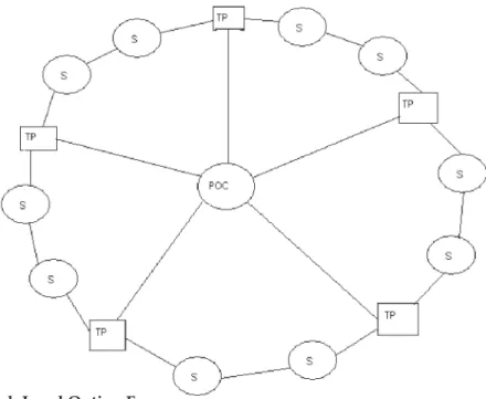
Figure 5 is a high level depiction of the to pol o gy of Option E. TP1 through TP5 are transfer points whose function will be ex plained below, and S1 through S10 are nodes on the network. The set of nodes situated between transfer points is called a group or a segment.
Though the fi gure is symmetrical with an equal number of stations in each group, this is not a requirement. The fi gure gests the stations and transfer points form a ring.
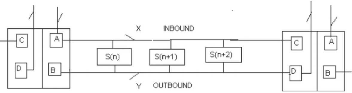
Figure 6 shows a detailed view of one group and the two transfer points to which it is attached. Further discussion of this pol o gy will be with reference to Fig. 6.
Figure 4. Option D.
subnet. Addresses on the same subnet are trans mit ted on outbound Line Y. Other ad-dresses are transmitted on inbound Line X to the POC.
Option D offers the same advantage as Option C: simpler node design. This to pol o gy overcomes the disadvantages
Figure 5. High Level Option E. Figure 5. High Level Option E.
Nodes transmit on inbound Line X and receive on outbound Line Y. Each transfer point performs the following functions: 1. A optical amplifi er for boost ing the
optical signal before transmitting it across the segment of the ring
2. B slot generator that gen er ates slots large enough to hold one packet of data
3. C terminator that removes data from the line after it is received
4. D optical amplifi er to boost the op ti cal signal before it is transmitted across the POC
Transmissions on inbound Line X tu al ly go through the POC and are mit ted to all other nodes through a transfer point and outbound Line Y. This topology presents several disadvantages:
1. This is not a single hop network, so lays can be expected to be longer than in a one-hop network.
2. Protocol design will be more com pli -cat ed.
3. Transfer points add an extra device not previously needed.
4. Transfer points add to the delay of a packet.
But it offers the following advantages: 1. Node design is simpler.
2. Transfer points can be built with rent ly available technology.
3. Existing protocols can be adapted to this topology.
4. The topology may offer more fl ex i bil i ty than either the ring or the star.
One other disadvantage worthy of dis cus sion is the bandwidth that may be
wast ed on transmission within a group. While it was an advantage in Option D, it may be lost in the move to Option E. An additional advantage in Options C, D, and E is the increase in the size of the networks possible. In the well studied star topology, there is only one station at the end of the lines to the POC. In these new to pol gies, there are several stations connected by one fi ber to the POC, which should allow many more nodes to be attached to the work. A variation of Option E allows great er fl exibility in communication capability, as explained in Option F.
Option F
The variation introduced in Option F is the design and function of transfer points. This new design is depicted in Fig. 7, which shows the addition of a new function to the transfer point, Function E.
Figure 7. Advanced TP – Option F. Figure 6. Low Level Option E.
Function E exists to transfer the signal either to the POC or to the optical amplifi er for inbound Line X of the next group. The addition of this function gives the network added communication options. If the sig nal entering E is sent to the POC, the network has the characteristics of a star LAN. If the signal entering E is sent to optical amplifi er A, the network takes on the characteristics of a ring network.
Function C will need to allow signals to pass to Function E for continued mis sion. How and when Device C needs to ter mi nate signals and which signals to ter mi nate requires communication between Func tions D and C. The set of channels will need to be split so some channels will be al lo cat ed for transfer through the POC and some for transfer through Device A. Function D could send information to Function C concerning which channels are currently being allocated to Function A. When a transmission on this channel is re ceived by C, C will not terminate the chan nel’s transmission.
This creates interesting possibilities in protocol design. It also offers some in ter -est ing ideas for types of services that could be offered by the network. The protocol could be designed so that applications that are more time sensitive would pass through the POC. Applications not time sensitive can be directed to the next group, as in a ring net work. Alternatively, the transfer point could simply transfer one set of wave-lengths across the star and a separate set of wave lengths around the ring. This could be ei ther a static or a dynamic assignment of wavelengths.
DISCUSSION
The previous sections were devoted to pre sent ing topological options for mu ni ca tion networks. Only the topologies were addressed. There was no consideration giv en to the potential cost, complexity, or feasibility of the topology; nor was there any serious considerations of protocol or
anal y sis. While it is necessary to have some dis cus sion related to potential protocols, and it is assumed the network will use wave length division multiplexing, design-ing a good protocol can be a complex task. It is beyond the scope of this article to propose any completely new protocols; however, some of the issues to be encountered can be addressed.
Issues involved with this topological Option A have already been addressed in the previous sections. Each bus sub net work can be treated as a single node attached to a POC, for which many protocols already ex ist (Henry 1989, Borella and Mukherjee 1995, Foo and Robertazzi 1995, Guo et al 1995, Lee and Un 1995, Levine and Akyildz 1995, Li et al 1995, Hua et al 1996, Muir and Garcia-Luna-Aceves 1996).
Whereas, in Option B, if WDM is used on a fi ber for both networks, some de ci sions must be made concerning the use of lengths between the bus subnet and the star network. One idea would be to divide the range of wavelengths into two groups, WB for use on the bus and WS for use on the star,
a static wavelength assignment strat e gy. This would allow for reuse of wave lengths on different bus subnetworks.
Another issue is the information need ed by each node. It is important for each node to know which nodes are on the same subnet and which are not. With this information, each node can use the correct network for communications with the desired des ti -na tion.
Topological Option C offers different issues that need to be addressed. Because most protocols designed for WDM on a star use a control channel in a Time Division Multiplexed (TDM) fashion, the concern is how to use the control channel in a TDM fashion to be fair to all stations.
If the nodes have a straight TDM al lo -ca tion on the control channel, some nodes will have an unfair advantage in trans mis -sion access. The most straightforward way to TDM the control channel is to assign slots
to nodes in order from the slot generator to-wards the POC. Thus, nodes nearer the slot generator will forever get fi rst trans mis sion opportunities.
One solution is to assign slots to sta tions on a cyclic permutation basis, dividing cess to the control channel into cycles. One cycle gives access of nodes to slots in a cy clic permutation of the previous cycle.
For example, if there are three nodes on the network, S1, S2, and S3, in the fi rst cy cle, nodes have access to slots in order (S1, S2, S3). In the next cycle, nodes have access in order (S2, S3, S1). In the next cycle, nodes have access in order (S3, S1, S2). The cyclic pattern is then repeated. Using this scheme, nodes will have fair opportunity for mis sion.
Topological Option D has the same chal leng ing solution as Option C. Addi-tionally, Device Z must have some way of deciding which channels need to be routed to out bound Line Y and which to the POC. It can be a completely passive process using a wavelength sensitive router if wavelengths are statically allocated to nodes to receive transmissions. Devices already exist for just this purpose (Rubin and Hua 1995).
However, if wavelengths are not stat i -cal ly assigned to nodes, Device Z’s task is an active one. Device Z must buffer at least part of the packet to inspect the destination address. This will allow the packet to be rout ed, but it will add some complexity and delay to the transmission. Either solution is possible, but the simpler one is preferred. Topological option E also presents the same challenges as Option C and requires the same solution. In addition, it presents added delays for a packet to traverse a group.
The fi nal topology, Option F, offers the same challenge encountered in Option B, the challenge of wavelength use on what is ef fec tive ly two different networks. The so lu tion could be as simple as the solution of fered for Option B: divide the range of wave lengths into two groups, WB and WS.
With this approach, Function E can perform
a wavelength sensitive routing function. However, there is still the challenge of stopping a packet from circulating forever. A potential solution is to let Function C spect each packet. A packet with a source address in the group preceding Device C is removed.
The above discussion is by no means exhaustive of all the issues encountered when designing a protocol for the pro posed topologies. Hopefully, it has brought up the issues of most concern.
CONCLUSIONS
This article has presented a number of new topologies that combine POC star with ring and bus networks. Only further research will tell which, if any, of these topologies are worth further investigation or de vel -op ment. Some advantages and disadvan-tages of each topology were mentioned. The article did not attempt to devise new protocols for the topologies, nor did it ad-dress any per for mance issues. Performance will be de pen dent on the design of suitable protocols.
A short discussion was provided which addressed some of the issues that may be encountered when designing protocols for the topologies. The purpose of this work is to generate interest in exploring new to pol o gies to expand the communication ca pa bil i ties of future networks.
The options that currently seem to of fer opportunities for further research are Op-tions D and F. Research would begin by de-signing a protocol suitable for the to pol o gy followed by a preliminary per for mance analysis.
REFERENCES
Acampora AS, Karol MJ. 1989. An over view of light-wave packet networks. IEEE Network 3(1):29-41. Borella MS, Mukherjee B. 1995. A res er va tion based
multicasting protocol for WDM local lightwave networks. Proc IEEE ICC: 1277-1281.
Foo EM,Robertazzi TG. 1995. A dis trib ut ed glo bal queue transmission strategy for a WDM optical fi ber network. Proc IEEE INFOCOM: 154-161. Guo D, Acampora AS, Zhang Z. 1995. A media ac cess
protocol for WDM star cou pled networks with non-equidistant sta tions. Proc IEEE ICC: 1288-1295 Henry PS. 1989. High capacity lightwave local area
networks. IEEE Com mu ni ca tions Magazine: 10: 20-26.
Hua C-J, Wang B, Han C-C. 1996. De sign and anal y sis of a WDMA protocol for passive star cou pled light-wave networks. Proc IEEE INFOCOM: 1225-1233. IEEE Std 802.6-1990. 1990. Distributed queue dual
bus (DQDB) subnetwork of a metropolitan area net work (MAN).
Lee JH, Un CK. 1995. Synchronous res er va tion pro to col for variable size mes sag es in WDM net works. Proc IEEE GLOBECOM: 2210-2214.
Levine DA, Akyildz IF. 1995. PRO TON: a media cess control protocol for optical networks with star topology. IEEE/ACM Trans on Networking 3(2):158-168.
Li B, Ganz A, Krishna CM. 1995. A nov el trans mis sion coordination scheme for sin gle hop lightwave works. Proc IEEE GLOBECOM: 1784-1788. Muir A, Garcia-Luna-Aceves JJ. 1996. Dis trib ut ed queue
packet scheduling al go rithms for WDM based net-works. Proc IEEE INFOCOM: 938-945.
Muller HR, Nassehi MM, Wong JW, Zurfl uh E, Bux W, Zafi ropulo P. 1990. DQMA and CRMA: a new ac cess scheme for Gbit/s LANs and MANs. Proc IEEE INFOCOM: 185-191.
Nassehi MM. 1990. CRMA: an access scheme for high speed LANs and MANs. Proc IEEE INFOCOM: 1697-1702.
Ramaswami R. 1993. Multiwavelength lightwave net works for computer com mu ni ca tions. IEEE Com mu ni ca tion Magazine: 2:78-88.
Rubin I, Hua H-K. 1995. SMARTNet: an all optical wavelength division meshed ring packet switch ing network. Proc IEEE GLOBECOM: 1756-1760.