Actuator controls
AUMATIC ACExC 01.2
Profibus DP
To be used in combination with the operation instructions only!
● The present short instructions do NOT replace the operation instructions!
● They are only intended for persons already familiar with the operation instructions where safety instructions, assembly, operation and commissioning are already described in detail!
Table of contents
Page
3 1. Short description... 4 2. FO connection... 4 2.1. Basic information 5 2.2. Terminal compartment: open6 2.3. FO cables: connect
7 2.4. Terminal compartment: close
8 3. Network topologies... 8 3.1. Line topology 9 3.2. Star topology 10 3.3. Ring topology (two-fibre ring)
12 4. Corrective action... 12 4.1. LED indications 12 4.2. Troubleshooting 13 4.2.1 Line and star topology
13 4.2.2 Ring topology 15 5. Technical data... 15 5.1. FO coupler 16 6. Appendix... 16 6.1. Calculation of achievable FO range
17 6.2. Measuring methods 17 6.3. Reference addresses 17 6.4. Literature Table of contents
1.
Short description
AUMA actuator controls with FO connection are intended for use in optical fieldbus networks.
The FO connection integrated in the electrical connection enables the conversion from electrical RS-485 signals into optical signals and vice versa.
FO connection behaviour is transparent at the bus, i.e. control of AUMA actuators via bus is identical to control via copper cables (RS-485).
Contrary to RS-485 based systems, different topologies are possible: ● Line topology
● Star topology
● Redundant ring topology
Apart from the large distances, FO cables offer further advantages: ● In environments with electromagnetic interference
● Lightning arrester or overvoltage protection ● Equipotential earth bonding and earthing ● Galvanic separation of the actuator
● Use of common cable trenches for power and signal cables ● Prevention of interference emissions along the transmission line
This allows for customised solutions and various applications such as water/waste water industries, tunnelling, power plants, thermal industry or telecontrol engineering.
2.
FO connection
2.1 Basic informationHazardous voltage!
Risk of electric shock. Failure to observe this warning can result in death or serious injury.
→ The connection must be carried out exclusively by suitably qualified personnel. → Prior to opening: Disconnect both system and device from the mains.
→ Observe basic information contained in this chapter.
→ Observe safety instructions contained in the operation instructions pertaining to the actuator.
Eye damage caused by open fibre optic cable ends!
→ NEVER look directly into open cable ends or FO cable connections.
Connection or receive problems when ignoring the installation instructions! → Only use FO cable connection (connector types) with the wiring techniques
in-dicated in these instructions.
→ Only mount connector types with locking mechanisms in the defined position. → Protect unused FO cable connections against contamination or dust with
protec-tive caps/plugs supplied by the factory.
→ Connect incoming FO cable with the optical receiver, the outgoing FO cable with the optical sender. NOT vice versa!
→ Do NOT kink FO cables! Observe bending radius of cable manufacturer. Cable and wire types
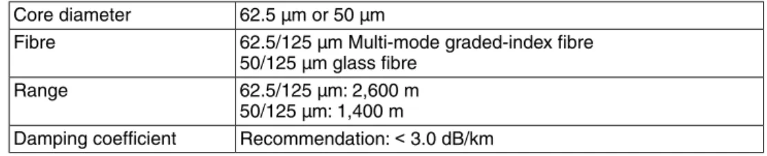
Table 1: Cables and wires according toDIN VDE 0888 part 3:
62.5 µm or 50 µm Core diameter
62.5/125 µm Multi-mode graded-index fibre 50/125 µm glass fibre Fibre 62.5/125 µm: 2,600 m 50/125 µm: 1,400 m Range Recommendation:< 3.0 dB/km Damping coefficient
Remove outer sheathing of FO cable at a length of approx. 25 cm to enable ring wiring in the terminal compartment.
Figure 1: Plug type FSMA
Controls mounted to wall bracket
In the event of heavy vibration of the valve, we recommend mounting the actuator controls separately from the actuator on a wall bracket. For information about the wall bracket, refer to operation instructions for the actuator.
2.2 Terminal compartment: open
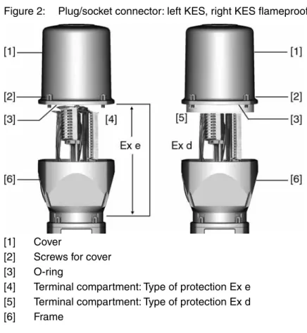
Figure 2: Plug/socket connector: left KES, right KES flameproof
[1] Cover
[2] Screws for cover [3] O-ring
[4] Terminal compartment: Type of protection Ex e [5] Terminal compartment: Type of protection Ex d [6] Frame
Hazardous voltage! Risk of electric shock.
→ Disconnect device from the mains before opening. 1. Loosen screws [2] and remove cover [1].
➥ Terminal compartments [4] and [5] are designed either in type of protection Ex e (increased safety) or in type of protection Ex d (flameproof enclosure). Hereby, the flameproof interior compartment of the actuator (Ex d) remains closed. 2. Insert cable glands with Ex e approval and suitable for connection cables. ➥ The enclosure protection IP… stated on the name plate is only ensured if
suita-ble casuita-ble glands are used. Example: Name plate shows enclosure protection IP 68.
3. Seal cable entries unused cable entries with approved plugs suitable for the required protection type.
4. Remove cable sheathing and insert the wires into the cable glands. 5. Fasten cable glands with the specified torque to ensure required enclosure
protection.
2.3 FO cables: connect
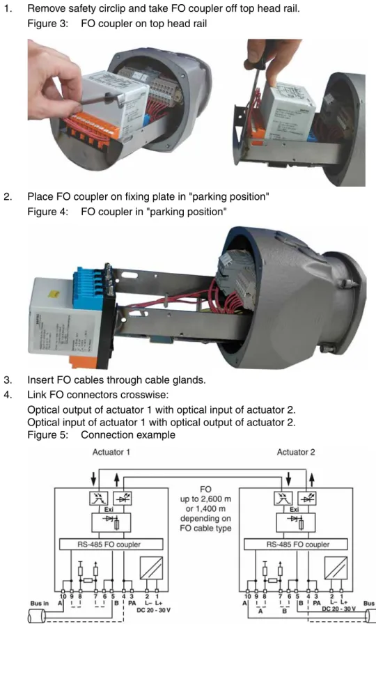
1. Remove safety circlip and take FO coupler off top head rail. Figure 3: FO coupler on top head rail
2. Place FO coupler on fixing plate in "parking position" Figure 4: FO coupler in "parking position"
3. Insert FO cables through cable glands. 4. Link FO connectors crosswise:
Optical output of actuator 1 with optical input of actuator 2. Optical input of actuator 1 with optical output of actuator 2. Figure 5: Connection example
2.4 Terminal compartment: close
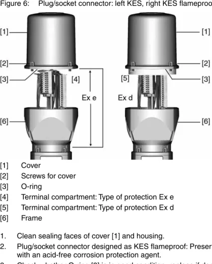
Figure 6: Plug/socket connector: left KES, right KES flameproof
[1] Cover
[2] Screws for cover [3] O-ring
[4] Terminal compartment: Type of protection Ex e [5] Terminal compartment: Type of protection Ex d [6] Frame
1. Clean sealing faces of cover [1] and housing.
2. Plug/socket connector designed as KES flameproof: Preserve joint surfaces with an acid-free corrosion protection agent.
3. Check whether O-ring [3] is in good condition, replace if damaged.
4. Apply a thin film of non-acidic grease (e.g. petroleum jelly) to the O-ring and insert it correctly.
Flameproof enclosure, danger of explosion! Risk of death or serious injury.
→ Handle cover and housing parts with care.
→ Joint surfaces must not be damaged or soiled in any way. → Do not jam cover during fitting.
5. Fit cover [1] and fasten screws [2] evenly crosswise.
3.
Network topologies
When connecting several field devices (actuators) in a network, the structure is called network topology. AUMA offers different network topologies.
3.1 Line topology
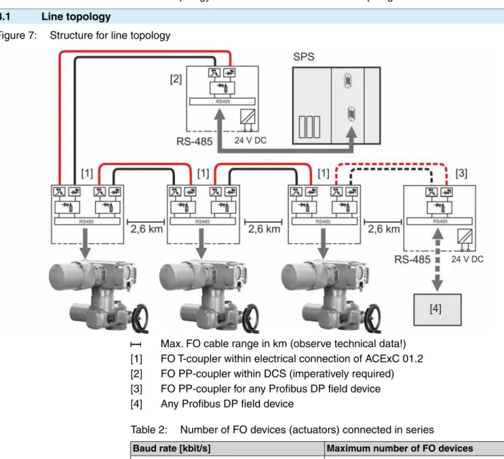
Figure 7: Structure for line topology
Max. FO cable range in km (observe technical data!) [1] FO T-coupler within electrical connection of ACExC 01.2 [2] FO PP-coupler within DCS (imperatively required) [3] FO PP-coupler for any Profibus DP field device [4] Any Profibus DP field device
Table 2: Number of FO devices (actuators) connected in series
Maximum number of FO devices Baud rate [kbit/s]
36 9.6 36 19.2 36 45.45 36 93.75 18 187.5 9 500 4 1,500
Special features of line topology
The optical signal is converted into an electrical signal at each device. Prior to transmission to the next device, the electrical signal is converted into an optical signal.
Interruption of an FO cable (case A) or failure of an FO connection board (case B) results in loss of control for the subsequent actuators:
Case A (standard)
As soon as the electrical connection is removed from the ACExC 01.2 , FO connection of this actuator is no longer available. As a consequence, communication with the subsequent actuators is lost. To prevent this, FO connection used in the ACExC 01.2 can also be externally supplied with 24 V DC.
Case B (option)
As soon as the actuator is switched off (motor voltage), the FO connection board of this actuator is no longer available. As a consequence, communication with the subsequent actuators is lost. To prevent this, the complete ACExC 01.2 can be externally supplied with 24 V DC.
3.2 Star topology
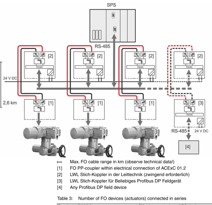
Figure 8: Structure for star topology
Max. FO cable range in km (observe technical data!) [1] FO PP-coupler within electrical connection of ACExC 01.2 [2] LWL Stich-Koppler in der Leittechnik (zwingend erforderlich) [3] LWL Stich-Koppler für Beliebiges Profibus DP Feldgerät [4] Any Profibus DP field device
Table 3: Number of FO devices (actuators) connected in series
Maximum number of FO devices Baud rate [kbit/s]
36 9.6 36 19.2 36 45.45 36 93.75 18 187.5 9 500 4 1,500
Special features of star topology
Failure of an FO cable section or of an actuator's FO connection board has no impact on the operability of the remaining actuators.
3.3 Ring topology (two-fibre ring) Figure 9: Structure for ring topology
Max. FO cable range in km (observe technical data!) [1] FO ring coupler within electrical connection of ACExC 01.2 [2] FO ring coupler within DCS (imperatively required)
[3] FO ring coupler for any Profibus DP field device [4] Any Profibus DP field device
Information Maximum number of FO device (actuators) connected in series is 36. Special features of ring topology
● The interruption of an FO cable between two actuators is recognised by the redundancy modules. Both display and bus indicate:Wrn FOC. The network
is then operated as an optical line and all actuators remain available. ● If one module fails (i.e. when power supply is interrupted), only the actuator
connected to this module is disconnected from the ring, the remaining network stays operative as a line. All other actuators remain available.
● The actuators have a redundant FO cable connection with a standard Profibus DP interface (not redundant).
Special features of the ring topology during configuration The following conditions have to be met for the optical ring
● Configuration of a non-existent bus station with the highest possible bus address. ● Increase of the retry value to a minimum of 3.
● Check slot time and set to a minimum of 900. ● Calculation of run times within the ring:
Tring = (n – 1) * TFO coupler + L * tFO Tring Max. run time within the ring
n Number of FO couplers within the ring
TFO coupler Module run time of the signals within the FO coupler = 4.5 ms L Length of the FO cables within the ring
TFO Run time per metre FO = 5 ns
The values indicated in the table apply to Profibus DP .
Max. distance bet-ween two FO couplers [km] Tring Run time within
ring [ms] Slot time [bit
ti-mes/km] Data rate [kbit/s]
0.7 0.30 900 1,500 2.2 0.90 900 500 2.6 2.40 900 187.5 2.6 4.80 900 93.75 2.6 9.90 900 45.45 2.6 23.44 900 19.2 2.6 46.88 900 9.6
● The FO coupler connected to the master via copper cable has to be a master module. Only one master module is allowed within the ring.
Cable routing and PLC fault evaluation
● To increase service safety, install cables for go-and-return in the ring on sepa-rate lines.
● To achieve complete monitoring of the redundant optical ring, all FO fault indi-cations (including the fault output of the FO coupler at the master) must be evaluated by the PLC controls.
4.
Corrective action
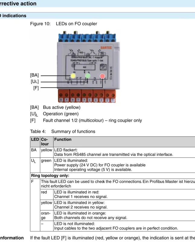
4.1 LED indicationsFigure 10: LEDs on FO coupler
[BA] Bus active (yellow) [U]L Operation (green)
[F] Fault channel 1/2 (multicolour) – ring coupler only Table 4: Summary of functions
Function
Co-lour LED
LED flackert:
Data from RS485 channel are transmitted via the optical interface. yellow
BA
LED is illuminated:
Power supply (24 V DC) for FO coupler is available Internal operating voltage (5 V) is available. green
UL
Ring topology only:
This fault LED can be used to check the FO connections. Ein Profibus Master ist hierzu nicht erforderlich
F
LED is illuminated in red: Channel 1 receives no signal. red
LED is illuminated in yellow: Channel 2 receives no signal. yellow
LED is illuminated in orange:
Both channels do not receive any signal.
oran-ge
LED is not illuminated:
Input cables to the two adjacent FO couplers are in perfect condition. –
Information If the fault LED [F] is illuminated (red, yellow or orange), the indication is sent at the same time via display and Profibus DP:Wrn FOC.Wrn FOC indication can be read
via fieldbus interface in the process representation input (byte 19). For an overview and a detailed description of all input data, refer to Manual (Device integration field-bus) AC 01.2/ACExC 01.2. Limitation: The Wrn FO cable budget and Wrn FOC connection indications represented in byte 20 are not generated for explosion-proof
version with FO cables. 4.2 Troubleshooting
LEDs on the FO couplers provide important information for troubleshooting. The following tables of this chapter provide basic steps for troubleshooting and elimination via these LEDs.
Furthermore, different fieldbus interface states can be requested via the ACExC 01.2 display (Menu Diagnostic M0022). For further information, please refer to “Manual
(Device integration fieldbus) AC 01.2/ACExC 01.2”. 4.2.1 Line and star topology
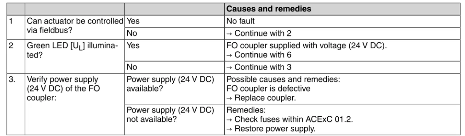
Table 5: Troubleshooting table
Causes and remedies
→ Continue with 4
Yes Can actuator be controlled via fieldbus?
1
→ Continue with 2
No
FO coupler supplied with voltage (24 V DC).
→ Continue with 4
Yes Green LED [UL]
illumina-ted? 2
→ Continue with 3
No
Possible causes and remedies: FO coupler is defective
→ Replace coupler.
Power supply (24 V DC) available?
Verify power supply (24 V DC) of the FO coupler:
3.
Remedies:
→ Check fuses within ACExC 01.2. → Restore power supply.
Power supply (24 V DC) not available?
Possible causes:
● Sender on coupler defective
● FO connection of sender not operable
Yes Is yellow LED [BA] flicke-ring?
4
Possible causes:
● Slave not properly connected ● Slave defective
● Master defective
● FO coupler receiver or FO connection of receiver defective ● Is the required FO coupler (BARTEC order no.:
07-7311-97WP/6000 or /4000) installed at the master? No
4.2.2 Ring topology
Troubleshooting ● Is the connection between FO coupler and device correct? ● Have all screw-type terminals been tightened correctly? ● Has the proper interface been selected?
● Is the transmission distance too long?
● Is the optical sender connected to the optical receiver of the opposite device? ● Are the bus termination resistors activated?
● Is an FO coupler, type BARTEC 07-7311-97WP/5400, connected to the fieldbus master?
● Is there more than one master module in the ring? Table 6: Troubleshooting table
Causes and remedies
No fault Yes
Can actuator be controlled via fieldbus?
1
→ Continue with 2
No
FO coupler supplied with voltage (24 V DC).
→ Continue with 6
Yes Green LED [UL] illumina-ted?
2
→ Continue with 3
No
Possible causes and remedies: FO coupler is defective
→ Replace coupler.
Power supply (24 V DC) available?
Verify power supply (24 V DC) of the FO coupler:
3.
Remedies:
→ Check fuses within ACExC 01.2. → Restore power supply.
Power supply (24 V DC) not available?
Causes and remedies
→ Continue with 5
Ja: LED illuminated in red, yellow or orange?
Fault LED [F] illuminated? 4
→ Continue with 6
No (LED is not illuminated)
Possible causes and remedies:
● Receiver at FO coupler defective ● Sender at adjacent FO coupler defective
→ Check FO cable. Yes
Check connection to adja-cent FO coupler (fieldbus device):
Connector ok? 5
Remedies:
→ Correct connection (connect optical output to optical input). No
Possible causes and remedies:
● Sender at coupler defective
● FO connection of sender not operable
→ Continue with 7
Yes Gelbe LED [BA] flackert? 6
Possible causes:
● Slave not properly connected ● Slave defective
● Master defective
No
Possible causes: Error in control program Yes
Check adjacent FO coupler (fieldbus device):
FO coupler ok? 7
→ Check adjacent FO coupler (fieldbus device). No
5.
Technical data
Information The following technical data includes standard and optional features. For detailed information on the customer-specific version, refer to the order-relevant data sheet. This data sheet can be downloaded from the Internet at http://www.auma.com in German and English (indication of commission number required).
5.1 FO coupler
Ex de [ib] IIC Explosion protection (in
accor-dance with EN 50014 to EN 50020)
Coupler: PTB 97 ATEX 1068 U Mounting: TÜV 99 ATEX 1404 X EC type examination
certifica-tes
FSMA FO plug/socket connector FO connection
For line topology: 1 x IN/OUT or 2 x IN/OUT For star topology: 1 x IN/OUT
For ring topology: 2 x IN/OUT Channels (optical) Maximum 1.5 Mbits/s Data rate Half-duplex Transmission type Multi-mode, 62.5 (50)/125 µm Fibre 8 dB at 62.5 µm 4 dB at 50 µm fibre Optical budget 62.5 µm glass fibre:
2,600 m (FO cable damping max. 3.0 dB/km, without additional damping) Network range max.
50 µm glass fibre:
1,400 m (FO cable damping max. 3.0 dB/km, without additional damping) 850 nm
Wave length
–25 °C to +60 °C Operation temperature
24 V DC/75 mA, internally supplied via power supply unit of ACExC 01.2.
For line and star topology: External power supply of the ACExC 01.2 with 24 V DC/500 mA possible. Only when the ACExC 01.2 is operated on external voltage supply will the bus remain uninterrupted in case of a loss of operating voltage.
Power supply
● LED UL (green) = device ready for operation (power supply available) ● LED BA (yellow) = bus active: Data is received via the RS485 channel.
For ring topology:
● LED fault (multicolour) = bus status
Indications (LEDs)
Profibus DP Suitable bus systems
Bartec, to be purchased from AUMA or www.bartec.de
● FO coupler for line or star topology - 1 channel FO PP coupler
(BARTEC order no.: 07-7311-97WP/6000) (AUMA order no.: K004.208)
- 2 channel FO T coupler
(BARTEC order no.: 07-7311-97WP/4000) (AUMA order no.: K006.014)
● FO coupler for ring topology: - 2 channel FO ring coupler
(BARTEC order no.: 07-7311-97WP/5400) (AUMA order no.: K006.015)
Required FO modules for the master
36 + 1 coupler at the master (at 93.75 kbit/s) Maximum number of FO
actua-tors
6.
Appendix
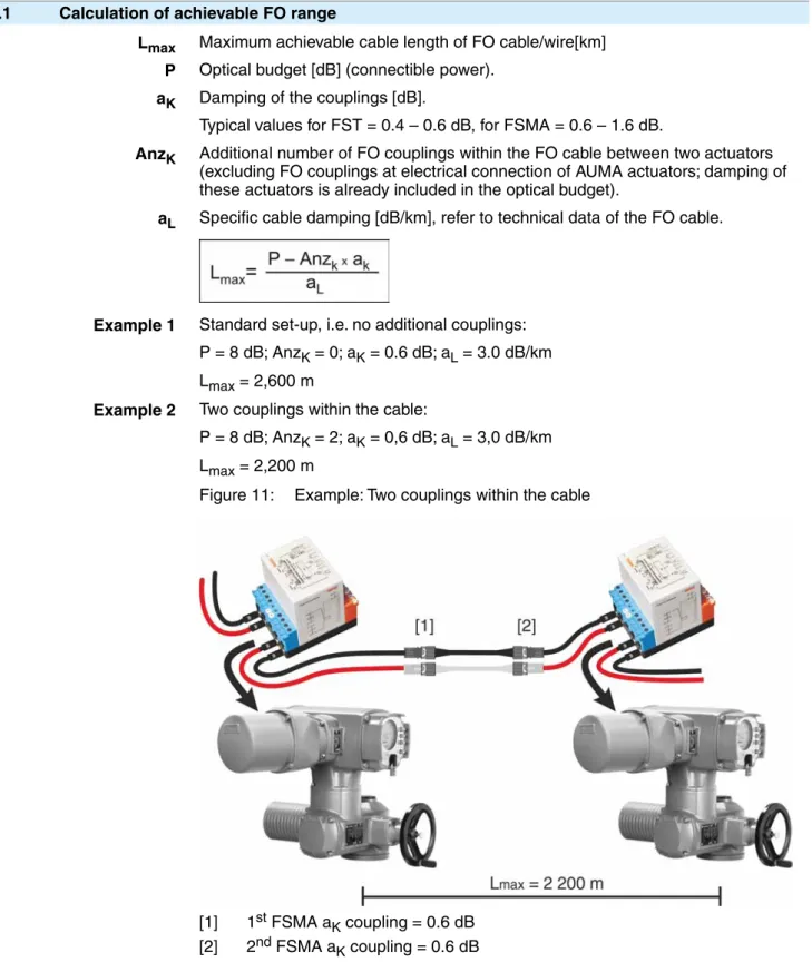
6.1 Calculation of achievable FO range
Lmax Maximum achievable cable length of FO cable/wire[km] P Optical budget [dB] (connectible power).
aK Damping of the couplings [dB].
Typical values for FST = 0.4 – 0.6 dB, for FSMA = 0.6 – 1.6 dB.
AnzK Additional number of FO couplings within the FO cable between two actuators (excluding FO couplings at electrical connection of AUMA actuators; damping of these actuators is already included in the optical budget).
aL Specific cable damping [dB/km], refer to technical data of the FO cable.
Example 1 Standard set-up, i.e. no additional couplings: P = 8 dB; AnzK = 0; aK = 0.6 dB; aL = 3.0 dB/km Lmax = 2,600 m
Example 2 Two couplings within the cable:
P = 8 dB; AnzK = 2; aK = 0,6 dB; aL = 3,0 dB/km Lmax = 2,200 m
Figure 11: Example: Two couplings within the cable
[1] 1st FSMA aK coupling = 0.6 dB [2] 2nd FSMA aK coupling = 0.6 dB Appendix
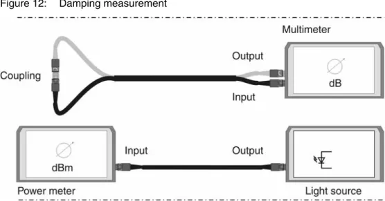
6.2 Measuring methods
Figure 12: Damping measurement
6.3 Reference addresses
● Required FO module for the master: BARTEC Top Holding GmbH Max-Eyth-Straße 16
D-97980 Bad Mergentheim Germany Tel.: +49 7931 597-0
Fax: +49 7931 597-119 www.bartec.de
● FO cables and wires:
Network reliability despite multiple points of failure eks Engel GmbH & Co. KG
Schützenstr. 2, 57482 Wenden-Hillmicke, Tel.: + 49-2762 - 9313 - 60,
www.eks-engel.de 6.4 Literature
● Christoph P. Wrobel
Optische Übertragungstechnik in der Praxis
Grundlagen, Komponenten, Installation, Anwendungen Hüthig Verlag
ISBN 3-7785-2638-3
AUMA Riester GmbH & Co. KG P.O.Box 1362 D 79373 Muellheim Tel +49 7631 809 - 0 Fax +49 7631 809 - 1250 [email protected] www.auma.com Y005.741/003/en/1.13